MAF Translator Gen
-
II
Use
r Manual
- - 4 - -
The primary function of the
MAF Translator Gen
-
II
is to allow the user to
adjust the air
-
fuel ratio of their engine. This is accomplished by adjusting
the amount of airflow the Engine Computer Module (ECM) or Engine
Control Unit (ECU) perceives
is entering the engine. If the ECM/ECU
senses less airflow is entering the engine, it will command less fuel be
injected into the engine, thus making the Air/Fuel ratio "leaner". If the
airflow signal is reduced by 1%, the resultant fuel delivery will b
e less by
1%.
For example, an engine is consuming 100 grams of air per second, and
the ECU is delivering fuel for 12:1 Air/Fuel Ratio (AFR). If the airflow
signal to the ECU is reduced to 95 grams per second (
-
5%)
, the
ECU will
delivery fuel for this amo
unt of air. The resulting AFR will be 12.6:1 (5%
leaner).
Main Airflow Modes
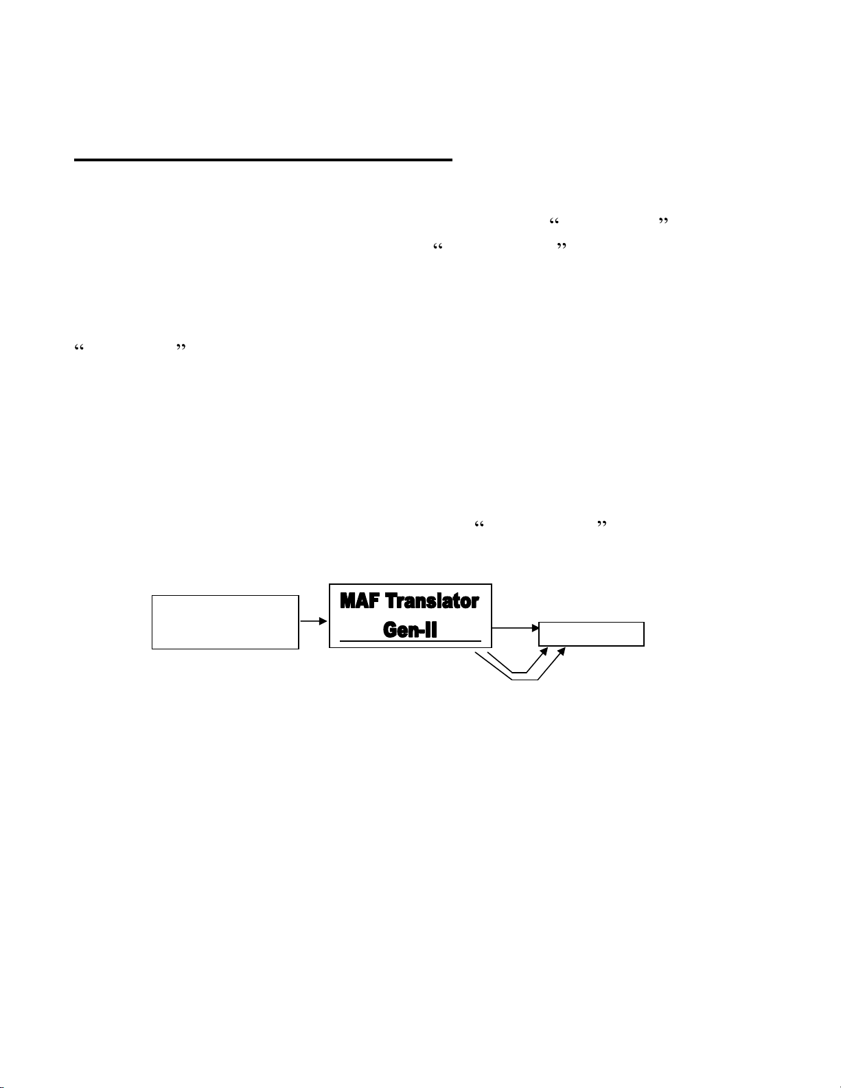
The
MAF Translator Gen
-
II
sends airflow information in the form of an
electrical signal (voltage or pulse frequency) to the ECU. Frequency signals
are send out
on the green,
"frequency out" wire of the 10 pin harness.
Voltage signals are sent
out
on the Brown (V Out 1) or the Gray (V out 2)
wires of the 10 pin
Main
harness.
The unit can be used to tune the vehicl
e
using the original MAF sensor,
or an upgraded, alternative sensor can be
used
.
Examples include using a GM LS1 or LS6 MAF on a Toyota Supra
,
Mitsubishi
Eclipse, or Ford SVO Mustang.
The MAF Translator Gen
-
II is
compatible with a great number of MAF sensors, both frequency
style
and
voltage.
Installation Details
This section contains installation details that are not specific to any particular
vehicle. Please refer to the appendix and other installation diagrams
contained in the
MAF Translator Gen
-
II
kit.
Harness connections are
referre
d to by connector desig
nation M or
A
(Main
or Aux
) and
pin number
,
for
example the +12V main power input is connected to the pink wire at M5
,
Ground at M10
.
In this manual, TAP means to connect to a harness wire
without cutting it. Splice means to cut a harness wire and co
nnect
MAF
Translator Gen
-
II
wires to the cut ends.
If a connection diagram specific to