MAG N 10 User manual

1
info@mag-audio.com
Tel./Fax: +38 044 277-47-89 www.mag-audio.com
N Series User Manual rev 0.1
User Manual
Systems:
N 10 N 10A
N 12 N 12A
N 15 N 15A
N S15 N S15A
N S18 N S18A
N SERIES

2
N Series User Manual rev 0.1
info@mag-audio.com
Tel./Fax: +38 044 277-47-89 www.mag-audio.com
This page has been intentionally left blank

3
info@mag-audio.com
Tel./Fax: +38 044 277-47-89 www.mag-audio.com
N Series User Manual rev 0.1
Contents ....................................................................................................... 3
1. Safety instructions ...................................................................................... 4
2. System description ...................................................................................... 5
3.1. Specifications - Technical data ..................................................... 6
3.2. Specifications - Dimensions ................................................................... 8
4.1. System operation - Rigging ..................................................... 10
4.2. System operation - Passive speakers .................................... 11
4.3. System operation - Powered speakers .................................... 12
4.4. System operation - Cardioid array subwoofer setup .. 14
5. Standard contents ...................................................................................... 15
6. Accessories ....................................................................................................... 15
Contents

4
N Series User Manual rev 0.1
info@mag-audio.com
Tel./Fax: +38 044 277-47-89 www.mag-audio.com
1. Safety instructions
1. Read these instructions carefully.
2. Keep these instructions.
3. Heed all warnings.
4. Follow all instructions.
5. Do not use this system near water.
6. Clean only with dry cloth.
7. Do not block any ventilation openings. Failure to do so may cause fast overheating and force
system to switch itself o.
8. Do not use the system near heat sources such as stoves, radiators or other equipment that
produces massive heat.
9. Do not use the system near open fire sources.
10. Connect the system only to the electric network with grounding.
11. Protect the power cord from being walked on, pinched, or otherwise damaged.
12. Use only accessories specified by the manufacturer.
13. Use only the cart, stand, tripod or bracket specified by the manufacturer, or sold with the unit.
When a cart is used, use caution when moving the cart with unit to avoid injury from tip-over.
14. Unplug this system during lightning storms or when unused for long periods of time.
15. Refer all servicing to qualified service personnel. Servicing is required when the system has
been damaged in any way, such as power supply cord or plug is damaged, liquid has been spilled or
objects have fallen into the unit, the unit has been exposed to rain or moisture, does not operate
normally, or has been dropped.
16. To completely disconnect this system from AC mains, disconnect the power supply cord from the
AC receptacle.
17. WARNING - TO REDUCE THE RISK OF FIRE OR ELECTRIC SHOCK, DO NOT EXPOSE THIS
SYSTEM UNIT TO RAIN OR MOISTURE.
18. The main plug of the power supply cord shall remain readily operable.
19. This system is capable of delivering a significant soundpressure levels. To avoid permanent or
temporary hearing damage, prolonged exposure to sound pressure levels exceeding 90 dB should
be limited
THIS SYSTEM CONTAINS POTENTIALLY LETHAL VOLTAGES. TO PREVENT ELECTRIC SHOCK OR
HAZARD, DO NOT REMOVE APLIFIER MODULE OR ITS PARTS. NO USER SERVICEABLE PARTS
INSIDE. REFER SERVICING TO QUALIFIED SERVICE PERSONNEL.
MOUNTING AND SUSPENSION OF THIS SYSTEM MUST BE PERFORMED ONLY BY QUALIFIED
TRAINED PERSONNEL FOLLOWING APPLICABLE SAFETY RULES. DO NOT ALLOW MOUNTING
OR SUSPENSION OF THIS UNIT IF MOUNTING OR SUSPENSION HARDWARE IS BROKEN, BENT,
PARTS ARE MISSING OR IS OTHERWISE DAMAGED.

5
info@mag-audio.com
Tel./Fax: +38 044 277-47-89 www.mag-audio.com
N Series User Manual rev 0.1
2. System description
The new generation of MAG Audio speakers is all neodymium N series. The sleek look, high perfor-
mance, lightweight, and powerful rigging capabilities, are all in one package.
Carefully designed and optimized neodymium transducers and high frequency drivers, designed
specifically for N series’ demanding standards, are made for reduced cabinet sizes and weight, while
providing unprecedented sound performance, in a very light and compact enclosures.
Equipped with easy-to-rig flying adapters, 10”, 12” and 15” full-range speakers cover all imaginable
compact speakers’ applications, from small scale FOH to backline, from installation to PA. Rein-
forced with low profile, performance optimized 15” and 18” subwoofers, the N series oers ultimate,
modern and versatile sound reinforcement solution.
Powered versions, based on state-of-the-art high eciency amplification modules, are made for
even more control and tuning capabilities. With several independent equalization options, it is easy
to set up N series rig for optimal sound in any environment. In addition, the networking adapters
provide distant controlling and fine tune conveniences, and make it possible to create sophisticated
sound reinforcement systems.
N 10 Part No. 0023500110
N 10-4 Part No. 0023500111
N 10A Part No. 0023500116
N 12 Part No. 0023500210
N 12-4 Part No. 0023500211
N 12A Part No. 0023500216
N 15 Part No. 0023500310
N 15-4 Part No. 0023500311
N 15A Part No. 0023500316
N S15 Part No. 0023500410
N S15-4 Part No. 0023500411
N S15A Part No. 0023500416
N S18 Part No. 0023500510
N S18-4 Part No. 0023500511
N S18A Part No. 0023500516
N S28 Part No. 0023500611
N S28A Part No. 0023500616

6
N Series User Manual rev 0.1
info@mag-audio.com
Tel./Fax: +38 044 277-47-89 www.mag-audio.com
3.1. Specifications - Technical data
System N 10 N 12 N 15
Type Full-range passive speaker Full-range passive speaker Full-range passive speaker
Frequency response (-10dB) 65 – 18000 Hz 60 – 18000 Hz 55 – 18000 Hz
Max SPL (peak) 131 dB (calculated) 132 dB (calculated) 132,5 dB (calculated)
Sensitivity (1W/1m) 97 dB 98 dB 98,5 dB
LF Transducer 10” 12” 15”
HF Transducer 1,5” 1,5” 1,5”
Nominal coverage HxV 90° x 80° 90° x 80° 90° x 80°
Impedance 8 Ohm / 4 Ohm 8 Ohm / 4 Ohm 8 Ohm / 4 Ohm
Nominal power (1) 600 W 600 W 600 W
Program power 1200 W 1200 W 1200 W
Peak power 2400 W 2400 W 2400 W
Connectors 2x Neutrik Speakon 2x Neutrik Speakon 2x Neutrik Speakon
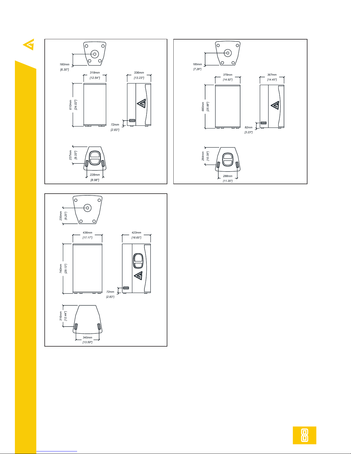
Dimensions (WxHxD) 319x610x336 mm 379x660x367 mm 436x740x423 mm
Net weight 19 kg 22 kg 26 kg
Shipping weight 22 kg 25 kg 29 kg
Mounting 4x FlyTrack flying points,
pole mount adapter
4x FlyTrack flying points,
pole mount adapter
4x FlyTrack flying points,
pole mount adapter
Enclosure materials Plywood; wear-resistant
paint
Plywood; wear-resistant
paint
Plywood; wear-resistant
paint
Grill Steel grill, polymer protec-
tive net
Steel grill, polymer protec-
tive net
Steel grill, polymer protec-
tive net
System N S15 N S18 N S28
Type Passive subwoofer Passive subwoofer Passive subwoofer
Frequency response (-10dB) 40 – 300 Hz 35 – 250 Hz 30-250 Hz
Max SPL (peak) 134 dB (calculated) 133 dB (calculated) 139,5 (calculated)
Sensitivity (1W/1m) 97 dB 96 dB 101,5 dB
LF Transducer 15” 18” 2x18”
Impedance 8 Ohm / 4 Ohm 8 Ohm / 4 Ohm 4 Ohm
Nominal power (1) 1200 W 1200 W 1600 W
Program power 2400 W 2400 W 3200 W
Peak power 4800 W 4800 W 6400 W
Connectors 2x Neutrik Speakon 2x Neutrik Speakon 2x Neutrik Speakon
Dimensions (WxHxD) 596x482x570 mm 656x512x604 mm 1096x560x642
Net weight 32 kg 40 kg 68,4 kg
Shipping weight 35 kg 43 kg 71,4 kg
Mounting M20 distance pole adapter M20 distance pole
adapter M20 distance pole adapter
Enclosure materials Plywood; wear-resistant paint Plywood; wear-resistant
paint
Plywood; wear-resistant
paint
Grill Steel grill, acoustically trans-
parent foam
Steel grill, acoustically
transparent foam
Steel grill, acoustically
transparent foam

7
info@mag-audio.com
Tel./Fax: +38 044 277-47-89 www.mag-audio.com
N Series User Manual rev 0.1
3.1. Specifications - Technical data
System N 10A N 12A N 15A
Type Full-range powered
speaker
Full-range powered
speaker
Full-range powered
speaker
Frequency response (-10dB) 65 – 18000 Hz 60 – 18000 Hz 55 – 18000 Hz
Max SPL (peak) 131 dB (calculated) 132 dB (calculated) 132,5 dB (calculated)
LF Transducer 10” 12” 15”
HF Transducer 1,5” 1,5” 1,5”
Nominal coverage HxV 90° x 80° 90° x 80° 90° x 80°
Power 1200 W 1200 W 1200 W
Amplifier Class D, Fan cooling Class D, Fan cooling Class D, Fan cooling
Input sensitivity 0 dBV 0 dBV 0 dBV
input impedance 18 kOhm (unbal),
36 kOhm (bal)
18 kOhm (unbal),
36 kOhm (bal)
18 kOhm (unbal),
36 kOhm (bal)
Connectors 2x XLR 2x XLR 2x XLR
Dimensions (WxHxD) 319x610x336 mm 379x660x377 mm 436x740x423 mm
Net weight 22 kg 25 kg 29 kg
Shipping weight 25 kg 28 kg 32 kg
Mounting 4x FlyTrack flying points,
pole mount adapter
4x FlyTrack flying points,
pole mount adapter
4x FlyTrack flying points,
pole mount adapter
Enclosure materials Plywood; wear-resistant
paint
Plywood; wear-resistant
paint
Plywood; wear-resistant
paint
Grill Steel grill, polymer protec-
tive net
Steel grill, polymer protec-
tive net
Steel grill, polymer protec-
tive net
System N S15A N S18A N S28A
Type Powered subwoofer Powered subwoofer Powered subwoofer
Frequency response (-10dB) 40 – 300 Hz 35 – 250 Hz 30-250 Hz
Max SPL (peak) 134 dB (calculated) 133 dB (calculated) 139,5 dB (calculated)
LF Transducer 15” 18” 2x18”
Power 1400 W 1400 W 3000 W
Amplifier Class D, Fan cooling Class D, Fan cooling Class D, Fan cooling
Input sensitivity 0 dBV 0 dBV 0 dBV
Input impedance 18 kOhm (unbal),
36 kOhm (bal)
18 kOhm (unbal),
36 kOhm (bal)
18 kOhm (unbal),
36 kOhm (bal)
Connectors 2x XLR 2x XLR 2x XLR
Dimensions (WxHxD) 596x482x570 mm 656x512x604 mm 1096x560x642
Net weight 35 kg 43 kg 71,4 kg
Shipping weight 38 kg 46 kg 74,4 kg
Mounting M20 distance pole adapter M20 distance pole adapter M20 distance pole adapter
Enclosure materials Plywood; wear-resistant paint Plywood; wear-resistant
paint
Plywood; wear-resistant
paint
Grill Steel grill, acoustically trans-
parent foam
Steel grill, acoustically
transparent foam
Steel grill, acoustically
transparent foam

8
N Series User Manual rev 0.1
info@mag-audio.com
Tel./Fax: +38 044 277-47-89 www.mag-audio.com
3.2. Specifications - Dimensions
N 10
N 10A
N 12
N 12A
N 15
N 15A

9
info@mag-audio.com
Tel./Fax: +38 044 277-47-89 www.mag-audio.com
N Series User Manual rev 0.1
N S15
N S15A
N S18
N S18A
3.2. Specifications - Dimensions
N S28
N S28A

10
N Series User Manual rev 0.1
info@mag-audio.com
Tel./Fax: +38 044 277-47-89 www.mag-audio.com
4.1. System operation - Rigging
N series systems are equipped with FlyTrack mounting adapters and pole mount adapters
systems for versatile applications.
Rigging must be performed only by trained personnel following the established safety rules.
MAXIMUM WEIGHT RESTRICTIONS MUST BE FOLLOWED AT ALL TIMES!
MAKE SURE THE SUPPORT STRUCTURE IS CAPABLE OF HOLDING THE APPLIED WEIGHT
WHILE SUSPENDING THE SYSTEM!
N series systems flying via FlyTrack mounting adapters.
Required accessories:
VA-0017 (part No. 0209000019)
Fast rigging and dismounting of N series full-range speakers using integrated FlyTrack adapters.
N series pole mounting
Accessories:
N-BOX-5 (part No. 0209000015)
N-BOX-4 (part No. 0209000016)
SAT-3T (part No. 0209000020)
N series full range speakers are
equipped with pole mount adapter,
which allows them to be installed onto
standard speaker stands.
N series subwoofers are equipped
with distance pole adapters, which
allow to install full-range systems
onto subwoofers using standard pole
stands.

11
info@mag-audio.com
Tel./Fax: +38 044 277-47-89 www.mag-audio.com
N Series User Manual rev 0.1
4.2. System operation - Passive speakers
N series passive full-range
speaker’s connection plate
N series passive subwoofer’s
connection plate
1
2
3
1. LABEL FIELD. Name of the system,
along with it’s basic parameters is
noted here.
2. SERIAL NUMBER FIELD. Sticker
with the systems serial number is
located here. NEVER REMOVE THE
SERIAL FROM THE SYSTEM, AS IT IS
IMMEDIATE WARRANTY VOID.
3. PARALLEL INPUTS. The pair
of parallel Neutrik® Speakon
connectors. Use this connectors to
connect power amplifier and to feed
the signal to the parallel system
(optional).
Made in Ukraine
PARALLEL INPUTS
Made in Ukraine by Magnet Ltd. www.mag-audio.com
1
2
3
N series passive connection diagram
N series passive connections
Suggested accessories:
CN-0031 (part No. 0204000010)
CN-0032 (part No. 0204000011)
Use power amplifier with DSP or power amplifiers
with external speaker processor with N series passive
systems.
MAKE SURE TO USE HIGH PASS FILTER FOR ALL N
SERIES SYSTEMS TO PREVENT EXCESSIVE CONE
MOVEMENT, RESULTING IN TRANSDUCER DAMAGE
OR FAST DETERIORATION.
Recommended HPF settings, suggested power
amplifier ratings, and connection pins are found in
table below:
System Amplifier power Amplifier impedance Connection pins Recommended HPF
N 10 600 - 1200 W 8 Ohm +1 -1 60 Hz or higher, 18 dB/oct min
N 10-4 600 - 1200 W 4 Ohm +1 -1 60 Hz or higher, 18 dB/oct min
N 12 600 - 1200 W 8 Ohm +1 -1 55 Hz or higher, 18 dB/oct min
N 12-4 600 - 1200 W 4 Ohm +1 -1 55 Hz or higher, 18 dB/oct min
N 15 600 - 1200 W 8 Ohm +1 -1 50 Hz or higher, 18 dB/oct min
N 15-4 600 - 1200 W 4 Ohm +1 -1 50 Hz or higher, 18 dB/oct min
N S15 1200 - 2400 W 8 Ohm +1 -1 35 Hz or higher, 18 dB/oct min
N S15-4 1200 - 2400 W 4 Ohm +1 -1 35 Hz or higher, 18 dB/oct min
N S18 1200 - 2400 W 8 Ohm +1 -1 30 Hz or higher, 18 dB/oct min
N S18-4 1200 - 2400 W 4 Ohm +1 -1 30 Hz or higher, 18 dB/oct min
N S28 1600 - 3200 W 4 Ohm +1 -1 28 Hz or higher, 18 dB/oct min
DSP AMPLIFIER
Speakon-Speakon
cable
Speakon-Speakon
cable
Speakon-Speakon
cable
Speakon-Speakon
cable
N series passive
full-range system
N series passive
full-range system
N series passive
sub
w
oo
f
e
r
N series passive
subwoofer

12
N Series User Manual rev 0.1
info@mag-audio.com
Tel./Fax: +38 044 277-47-89 www.mag-audio.com
4.3. System operation - Powered speakers
N series powered full-range
speaker’s amplifier
N series powered subwoofer’s
amplifier
1
3
2
4 5 6
11
10
12
13 14
1
3
2
7 8 9
11
10
12
13 14
1. VOLUME KNOB. Used for adjusting the
volume of the system. Remember to turn
the volume dowm before connecting/
disconnecting INPUT or LINK connectors.
2. LIMIT LED. Is lit when limiter is
operational, indicating excessive signal
through the system.
3. READY LED. Is lit when system is fully
operational.
4. HPF 100 HPF BUTTON. Engages the
100 Hz high-pass filter.
5. MID CUT BUTTON. Engages the mid cut
contour.
6. HF BOOST BUTTON. Engages HF boost
contour.
7. CARDIOID BUTTON AND LED. Used for
cardioid LF arrays.
8. PHASE BUTTON. Switches the polarity
of the subwoofer.
9. LPF BUTTON. Engages the low-pass
filter.
10. INPUT CONNECTOR. Used for
connecting the system to the signal source
(mixing console etc.)
11. LINK CONNECTOR. Used for linking
additional compactible system to same
signal source.
12. HEAT SINK. Do not close the ventilation
openings on the heat sink, as it may cause
the system to overheat and switch o by
itself.
13. MAINS IN. Used for connecting mains
supply to the system.
14. MAINS OUT. Used for feeding the mains
supply to the additional system.

13
info@mag-audio.com
Tel./Fax: +38 044 277-47-89 www.mag-audio.com
N Series User Manual rev 0.1
4.3. System operation - Powered speakers
Mains connection. N series powered systems are supplied with CN-0010 PowerCon-E/F CEE 7/7
mains cable (part number 0204000003). Use only original or supplied by manufacturer mains
cables!.
N series powered systems are equipped with PowerCon B mains power outlets for mains link to
additional N series powered system.
N series systems nominal mains power specifications: AC 220V, 50/60 Hz.
Nominal voltage tolerance: 100 - 250 V.
To power the system up, connect the mains cable to the system, then to the power outlet.
To completely power down the system, disconnect the mains cable from the power outlet.
Signal connections. N series systems are equipped with XLR INPUT an XLR LINK connectors for
signal connection.
Use of balanced XLR connector cables is recommended. In case when balanced XLR connections in
not available, unbalanced XLR connection is acceptable.
For linking the additional system to the same signal bus LINK connector may be used.
1
2
3
Shield (Ground)
Plus (+)
Minus (-)
Balanced XLR Plug connections
1
2
3
Shield (Ground)
Plus (+)
Shield (Ground)
Unbalanced XLR Plug connections
N series powered connection diagram
Amplifier controls. Use several available N
series speaker system’s amplifier controls
to set up the entire system:
HPF 100 Hz (full-range system): Provides
high-pass filter to seamlessly couple
the full-range system with powered
subwoofer.
MID CUT (full-range system): Provides mid
cut correction for cleaner and smoother
sound.
HF BOOST (full-range system): Provides
HF boost for far-field systems.
CARDIOID (subwoofers): Engages cadioid
mode (see “4.4 System operation -
cardioid array subwoofer setup” section,
page 14, for details.).
PHASE (subwoofers): Switches the polarity
of the subwoofer for better coupling
with the full-range systems for dierent
applications.
LPF (subwoofers): Provides low-pass filter
to seamlessly couple the subwoofer with
powered full-range system.
XLR-XLR cable XLR-XLR cable
N series powered
full-range system
N series powered
full-range system
N series powered
subwoofer
N series powered
subwoofer
XLR-XLR cable XLR-XLR cable
To signal source

14
N Series User Manual rev 0.1
info@mag-audio.com
Tel./Fax: +38 044 277-47-89 www.mag-audio.com
4.4. System operation - Cardioid array
subwoofer setup
Instal subwoofers onto in a way that main sub-
woofer is facing the same way as the rest of the
PA system, while the inverted subwoofer is rotated
180 degrees. Frontal panel of the main subwoofer
and rear panel of the inverted one should be on
the same plane.
For the frontal unit, put the VOLUME knob in
“0 dB“ position.
For the inverted unit, put the VOLUME knob in
12 o’clock position and activate the CARDIOID
mode, indicated by a LED indicator.
N series’ powered subwoofers - N S15A and N S18A - allow to create low frequency cardioid arrays for con-
trolled sound enviroment and listening comfort.
Use following guidelines to achieve best results with your N series powered subwoofer
cardioid arrays:
Two unit cardioid array:
N series subwoofer’s control panel
CARDIOID mode button and LED
indicator
VOLUME
knob
Two unit cardioid array
volume knobs positions
Main
subwoofer
Inverted
subwoofer
Three unit cardioid array
volume knobs positions
Main
subwoofer
Inverted
subwoofer
Instal subwoofers onto in a way that main sub-
woofers are facing the same way as the rest of the
PA system, while the inverted subwoofer is rotated
180 degrees. Frontal panel of the main subwoof-
ers and rear panel of the inverted one should be
on the same plane. It is advised to locate inverted
subwoofer between main subwoofers.
For the frontal units, put the VOLUME knob in
“0 dB“ position.
For the inverted unit, put the VOLUME knob in
“0 dB” position and activate the CARDIOID mode,
indicated by a LED indicator.
Three unit cardioid array:
Two unit and three unit cardioid array
Frontal
unit
Inverted
unit
Frontal
unit

15
info@mag-audio.com
Tel./Fax: +38 044 277-47-89 www.mag-audio.com
N Series User Manual rev 0.1
6. Accessories
Various accessories are available for N series systems:
N-BOX-5 speaker
stand
Part No. 0209000015
5. Standard contents
Please check complete complement of your N series system upon receiving the package.
Standard contents of N series systems:
N10-TB - N 10, N 10-4, N 10A transportation bag Part No. 0203500073
N12-TB - N 12, N 12-4, N 12A transportation bag Part No. 0203500075
N15-TB - N 15, N15-4, N 15A transportation bag Part No. 0203500077
NS15-TB - N S15, N S15-4, N S15A transportation bag Part No. 0203500079
NS18-TB - N S18, N S18-4, N S18A transportation bag Part No. 0203500081
System Supplied N series system N series
User Manual
CN-0010
PowerCon mains
cable
Polyethylene
bag Carton Box
N 10 N 10 8 Ohm passive speaker system + + +
N 10-4 N 10 4 Ohm passive speaker system + + +
N 10A N 10A powered speaker system + + + +
N 12 N 12 8 Ohm passive speaker system + + +
N 12-4 N 12 4 Ohm passive speaker system + + +
N 12A N 12A powered speaker system + + + +
N 15 N 15 8 Ohm passive speaker system + + +
N 15-4 N 15 4 Ohm passive speaker system + + +
N 15A N 15A powered speaker system + + + +
N S15 N S15 8 Ohm passive speaker system + + +
N S15-4 N S15 4 Ohm passive speaker system + + +
N S15A N S15A powered speaker system + + + +
N S18 N S18 8 Ohm passive speaker system + + +
N S18-4 N S18 4 Ohm passive speaker system + + +
N S18A N S18A powered speaker system + + + +
N S28 N S28 4 Ohm passive speaker system + + +
N S28A N S28A powered speaker system + + + +
N-BOX-4 speaker
stand
Part No. 0209000016
SAT-3T M20
Distance pole
Part No. 0209000020
VA-0017 FlyTrack
single point stud
Part No. 0209000019
BOX-CB2 Bag for
for two speaker
stands
Part No. 0209000017

16
N Series User Manual rev 0.1
info@mag-audio.com
Tel./Fax: +38 044 277-47-89 www.mag-audio.com
info@mag-audio.com
Tel./Fax: +38 044 277-47-89 www.mag-audio.com
MANUFACTURER’S WARRANTY
1. By this warranty MAG Audio grants that all equipment manufactured under the MAG Audio
trademark is free from defects in material, components and factory workmanship under the
normal use and maintenance for the time as specified below.
2. All warranty repairs and maintenance of MAG Audio products shall be carried out at MAG
Audio production sites or by MAG Audio authorized personnel at no cost for the product pur-
chaser.
3. Warranty period for all the MAG Audio products is 36 months from the date of purchase.
4. Warranty repairs or maintenance will be performed only if a) MAG Audio product was pur-
chased from an ocial MAG Audio distributor / dealer and b) warranty card with specified serial
number, production date, realization date, vendor’s signature and stamp is presented.
5. Warranty shall not cover following: damage caused by accident, misuse or failure to follow
exploitation rules stated in technical manual; repairs performed by non-authorized personnel;
mechanical damage caused by shipping accidents and normal tear and wear.
6. Warranty shall not be applicable to any product with defaced, removed, or modified serial
number.
7. If your MAG Audio product needs repairs or maintenance, contact your ocial MAG Audio
distributor / dealer. Please do not ship your MAG Audio product without prior authorization.
MANUFACTURER’S CONTACTS
2 Merezhna street, Bila Tserkva, Kiev region, 09112, Ukraine
Tel.\Fax: +38 044 277 47 89
e-mail: info@mag-audio.com
www.mag-audio.com
YOUR MAG AUDIO DISTRIBUTOR / DEALER
Company
Contact
person
Coordinates
This manual suits for next models
9
Table of contents
Other MAG Speakers manuals
Popular Speakers manuals by other brands

NEAR
NEAR LB5/T quick start guide

Definitive Technology
Definitive Technology Mythos Mythos STS owner's manual

ERJK
ERJK CONFERENCE Series instruction manual

Bogen
Bogen IH-8A install guide

Revox
Revox AGORA B MKII Service instructions

Acoustic Research
Acoustic Research AW-871 Installation and operation manual