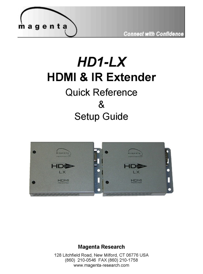
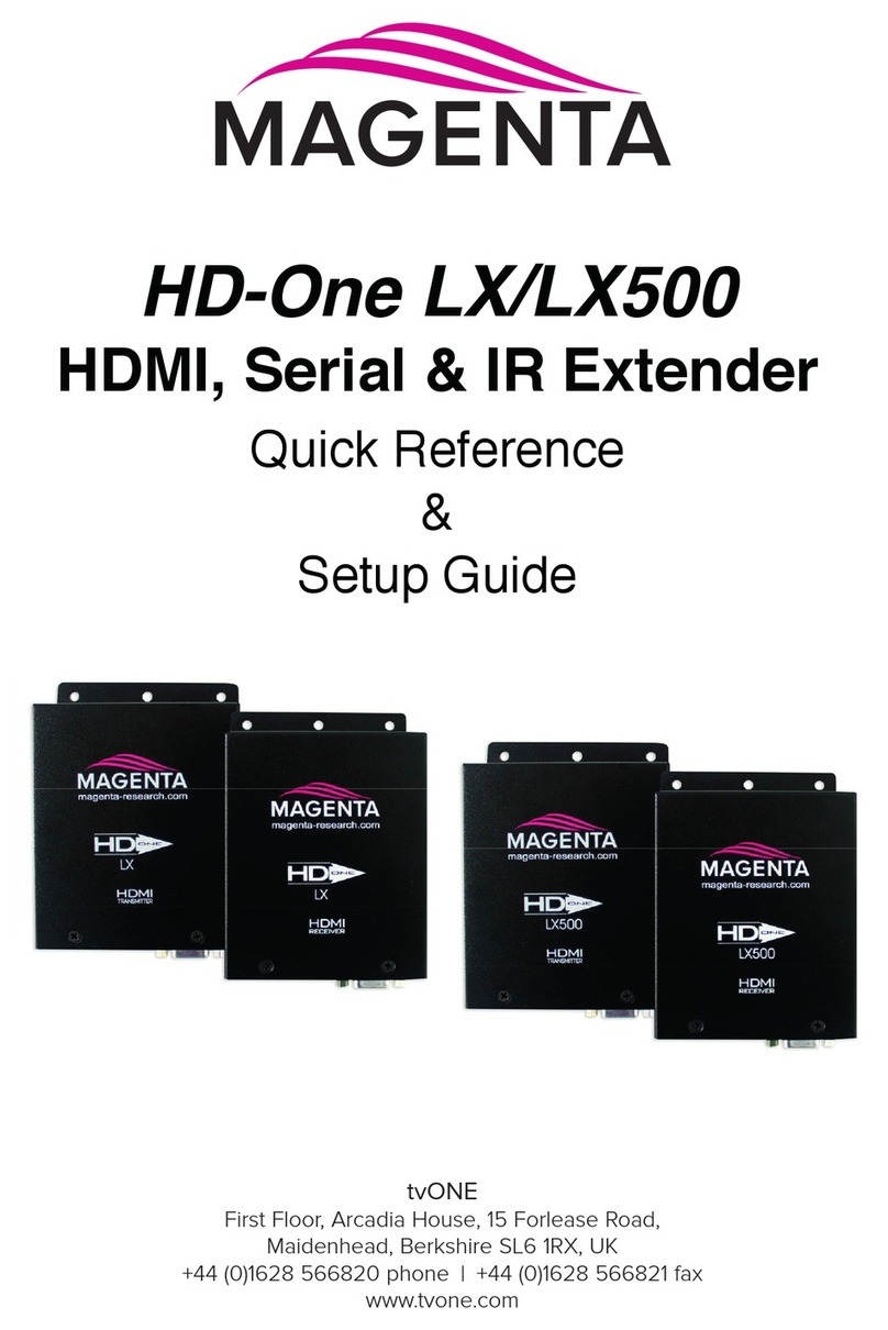
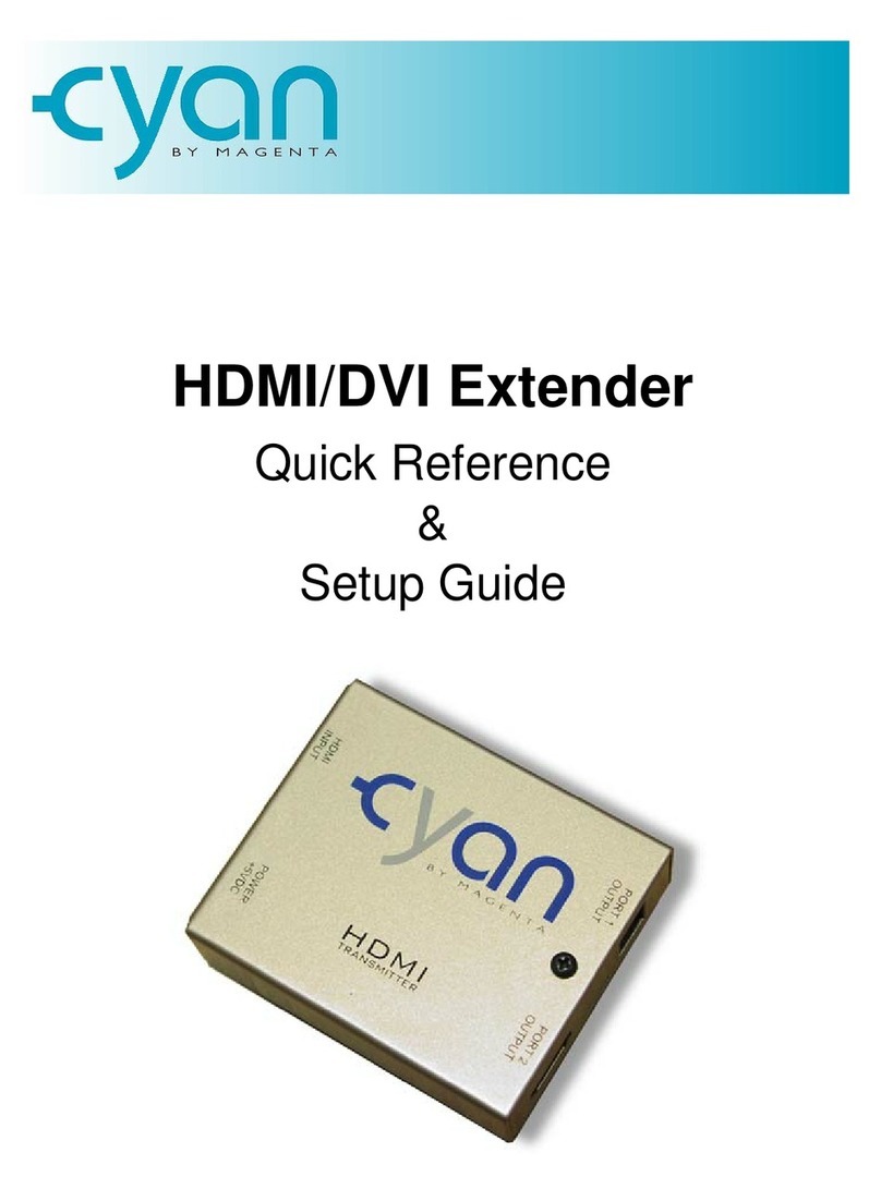
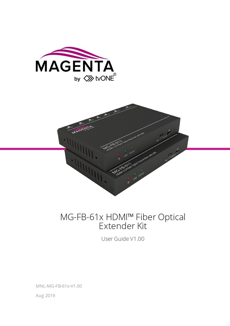
Magenta 4 Play User manual

MAGENTA 4 PLAY SERIES
Magenta Research
128 Litchfield Road, New Milford, CT 06776 USA
(860) 210-0546 FAX (860) 210-1758
www.magenta-research.com
PN: 5310192-01, Rev 01, 08/07
.
4 Play
4 port DVI Extender
Quick Reference
&
Setup Guide
Magenta Research
128 Litchfield Road, New Milford, CT 06776 USA
(860) 210-0546 FAX (860) 210-1758
www.magenta-research.com

MAGENTA 4 PLAY SERIES Contents
Chapter Page
1. Specifications...................................................................................................2
2. Introduction ........................................….........................................................3
2.1 Overview................................................................................….................3
2.2 Equipment You May Also Need..........................................................…....3
2.3 Compatible Cabling ........................................................................…...….3
3. Setup and Installation.......................................… ......................................….4
3.1 Cabling Considerations.................................................................................4
3.2 Making the Connections.....................................................................…......5
3.2.1 Connections and Setup in General .......................................……......5
3.2.2 Connections on the Transmitter and Receiver…..............………..…..5
4. Troubleshooting..............................................................................................6
4.1 Common Problems .....................................................................................6
Appendix A. Cabling Pinouts.........................................….....................................6
© 2007 by Magenta Research All rights reserved.
Magenta Research
128 Litchfield Rd
New Milford, CT. 06776 USA
This document and the Magenta Research products to which it relates, and the copyright in each, is the
property of Magenta Research. Neither the document nor the products may be reproduced by any
means, in whole or in part, without the prior written permission of Magenta Research. Magenta Research
makes no warranty or representation, either express or implied, with respect to this software or
documentation, including their quality, performance, merchantability, or fitness for a particular purpose.
As a result, this software or documentation are licensed "as is" and you, the licensee, are assuming the
entire risk as to their quality and performance.
In no event will Magenta Research be liable for direct, indirect, special, incidental, or consequential
damages arising out of the use of or inability to use the software or documentation.
Magenta Research and the Magenta Research logo are trademarks of Magenta Research.
All other brands, product names, and trademarks are the property of their respective owners
1
.
1. Specifications
Cable Required: Category 5, 5e, 6 screened twisted pair (ScTP)
Video Support: DVI Video modes
Maximum
Resolution and
Refresh Rate: 1080P, 1600x1200 (UXGA)
Bandwidth: 4.95 Gbps
Connectors: (2) DVI-D, (4) RJ-45, (1) DC power inlet
Temperature
Tolerance: Operating: 32 to 104°F (0 to 40°C);
Storage: -4 to +140°F (-20 to +60°C)
Humidity
Tolerance: Up to 80% noncondensing
Enclosure: Metal
Power: +5 VDC @ 1.25 A max, Consumption: 6.25 watts maximum
Size: 1.25 "H x 4.25"W x 4.25"D (3.2 x 10.8 x 10.8 cm)
Weight: 0.81 lb. (0.37 kg) - each
Recommended
maximum cable lengths:
Screened UTP (ScTP)
UXGA, 1080P 150 ft
720P, 1080I 300 ft
2. Introduction
2.1 Overview
The Magenta 4Play DVI video extenders extend 4 DVI signals over Category 5/5e/6 cable.
Screened Cat5/5e/6 (ScTP) should be used for best video quality and to minimize EMI interference
from external sources as well as interference from electrical noise on ground. Unshielded twisted
pair may produce undesirable results. Each display device requires a Magenta Cats’ I receiver
unit (sold separately) .
WARNING
This equipment is not intended for, nor does it support, distribution
through an Ethernet network. Do not connect these devices to any sort
of networking or telecommunications equipment!
2.2 Equipment You May Also Need
• DVI M-M cables
• HDMI to DVI cable adapter
• Screened CAT5 cable (ScTP)
2.3 Compatible Cabling
Magenta Research products are compatible with screened (ScTP) Cat5/5e/6 data cabling.
Note: The shielding on the cable MUST be connected at both ends using compatible
screened RJ45 plugs. Failure to connect the cable shield at either end may affect video
performance and allow signal interference. Contact cable manufacturer for appropriate
connectors and instructions.
CAT5/5e/6 cabling for the Magenta 4Play Series must be pinned to the TIA-EIA T568B wiring
specification (see appendix A) We also highly recommend that all CAT5/5e/6 cables be pre-
terminated and tested. Cables terminated on-site or in an existing infrastructure should be tested
before use to ensure compliance with the TIA-EIA T568B specification. Using incorrectly
terminated CAT5/5e/6 cables can damage the Magenta 4Play Series.
At the time of printing this manual, Magenta Research recommends Belden 1533 ScTP cable with
Tyco (AMP) 5-569550 RJ-45 connectors. Please follow cable termination guidelines to ensure the
shield is correctly connected on both ends of the cable.
Specifications
2

MAGENTA 4 PLAY SERIES
3. Setup and Installation
3.1 Cabling Considerations
• We recommend mounting and connecting all cabling to the 4Play and Cat’s I
Series components before applying power.
• Make sure that the CAT5/5e/6 cable you intend to use has been tested to comply
with the T568B wiring specification and the shield is properly grounded (See
Appendix A).
3.2 Making the Connections
3.2.1 Connections and Setup
NOTE:
All units should be cabled and powered on prior to turning on the video source
device and display. It is recommended to cable/power on the 4Play, Cat’s I’s, then
the display, and lastly the video source.
At the 4Play transmitter end:
1. Connect the source video to the 4Play transmitter DVI INPUT port using a DVI
cable (If using HDMI video an HDMI to DVI adapter is required).
2. Connect the CAT5/5e/6 cable to the transmitter. 4Play does not support HDCP
so protected content will not be displayed.
3. Apply power to the transmitter. The LED’s on the RJ45 sockets will come
on - see Figure 3-3 for LED status modes
At the Cat’s I receiver end :
1. Connect the display to the HDMI OUTPUT connector on the receiver (If a
DVI connector is on the display, an HDMI to DVI adapter is required).
2. Connect the CAT5/5e/6 cable to the Port 1 UTP connector. 4Play does not
support HDCP so protected content will not be displayed.
3. Apply power. The LED’s will come - see Figure 3-3 for LED status modes.
You may need to change the DDC operating Mode in order to properly display
certain screen resolutions. See bottom of 4Play unit or Appendix B for instructions.
3
.
CHAPTER 3: SETUP & INSTALLATION
4
3.2.2 Connections on the 4Play transmitter and Cat’s I receiver
Figure 3-1 shows the 4Play transmitter connections, and Figure 3-2 shows the
Cat’s I receiver connections. Figure 3-3 explains the LED status lights on the RJ-
45 connector.
Figure 3-1. Connections on the 4Play Transmitter
Figure 3-2. Connections on the Cat’s I Receiver
Figure 3-3. LED Status Indicators
Power Indicator
LED’s
Transmitter:
UTP Link Established with Receiver
Receiver:
Link established with transmitter

MAGENTA 4 PLAY SERIES
4. Troubleshooting
4.1 Common Problems
THERE ARE NO INTERNALUSER CONFIGURABLE SETTINGS FOR 4PLAY or CAT’s I
In most cases, nearly every issue with the 4Play or Cat’s I Series can be resolved by
checking the CAT5/5e/6 termination and making sure that it’s pinned to the T568B
wiring specification. However, there may be other problems that cause the system to
not perform as it’s intended. Below are solutions to the most common installation errors.
Problem: No video or poor video quality.
Solution: • Check that both units are powered.
• Power units in the sequence noted in section 3.2.1.
• Make sure the UTP cable is terminated correctly per the
568B wiring specification.
• Ensure screened Cat5/5e/6 cable (ScTP) is used and the shield is
properly connected at each RJ45 end.
• Is the display device powered on and functioning?
• Video source may need DDC information from display. See
Appendix B.
• Some HDMI sources can take up to 5 minutes to initialize and will
not output video signals during this time.
• Cell phones may cause interference at close range (3 ft) and cause
the video signal to be interrupted or lost. All devices may need to be
power cycled if video is lost.
Appendix A. Cabling Pinouts
Table A-1. T568B CAT5 pinout
5
.
Appendix B: DDC/EDID Modes
6
Appendix B. DDC/EDID Modes
The 4Play DVI transmitter features the ability to send DDC/EDID display identifiers to the video
source in order to determine display capabilities. The DDC is a data communication channel used
in plug and play devices to accurately report a displays capabilities and identify the manufacturer.
If this data is not available, the video source may revert to a low resolution or not display at all.
4Play DVI transmitter features the ability to report a Universal Display (MRI Magic Display) that
supports most popular VESA standards in standard or widescreen formats as well as the ability to
clone an actual displays DDC information that is attached to the DVI input of the transmitter or
pass DDC information from a local display attached to the DVI Local Output of the transmitter.
The various modes are detailed below:
Mode 1: Universal Display (MRI Magic Display) (DEFAULT)
This mode reports a generic display supporting popular screen formats and is
suitable for most if not all display types.
Mode 2: Pass through DDC from DVI Local Output of transmitter.
This mode passes the DDC from a display permanently attached to the local output of
the transmitter. Removing this display will result in no DDC information passed to the
video source and may result in lower resolution or no display.
Mode 3: Clone DDC from display on the DVI Input port and stores it in non-volatile Ram
This mode copies the DDC data from a display attached to the DVI Input and stores it in
non-volatile RAM. It is not necessary to connect a DVI display to the local output in this
mode.
To change modes requires dipswitches on the bottom of the unit to be changed:
Mode 1: Default mode. To restore, with power disconnected, set switches as per diagram 1)
below. Connect power and move SW1 to ON as shown in diagram 2). Observe the
yellow LED’s on the left side of the RJ45 connectors. If the operation succeeds, they will
blink 3 times.
1) 2)
Mode 2: To pass DDC from a display connected to the local DVI output of the transmitter, set
switches as follows in diagram 3) with power off, then connect appropriate cables and
power on unit. Display must be connected at all times or DDC information will not be
transmitted and display may not initialize.
3)
Mode 3: To clone DDC from a display connected to the DVI Input of the transmitter and store it
non-volatile RAM, set switches as per diagram 4) with power off, connect display to the
DVI INPUT port, power on display, then power on transmitter. Next move SW1 from ON
to OFF as per diagram 5). Observe the yellow LED’s on the left side of the RJ45
connectors. If the operation succeeds, they will blink 3 times. Disconnect display and
install equipment as discussed in Section 3 of this manual.
4) 5)
Other Magenta Extender manuals
Popular Extender manuals by other brands

ZyXEL Communications
ZyXEL Communications AeroBeam WHD6215 Easy setup guide

Rose electronics
Rose electronics CrystalView EX5 Installation and operation manual

D-Link
D-Link AMPLIFI DAP-1525 user manual

Ihse
Ihse KVM-TEC ScalableLine 4K/5K Quick Instruction

Vertiv
Vertiv HMX3080T user manual

MuxLab
MuxLab VideoEase installation guide