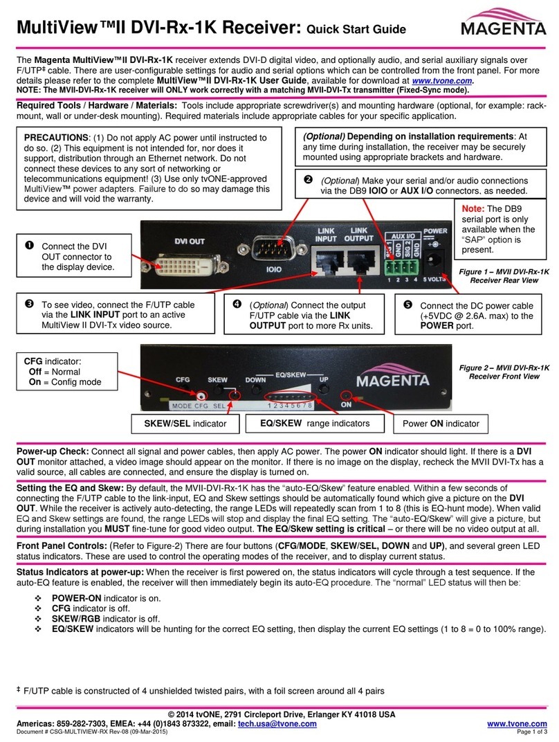
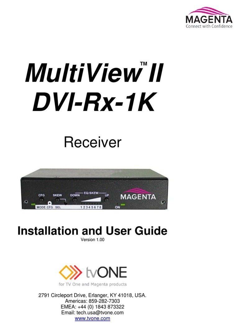
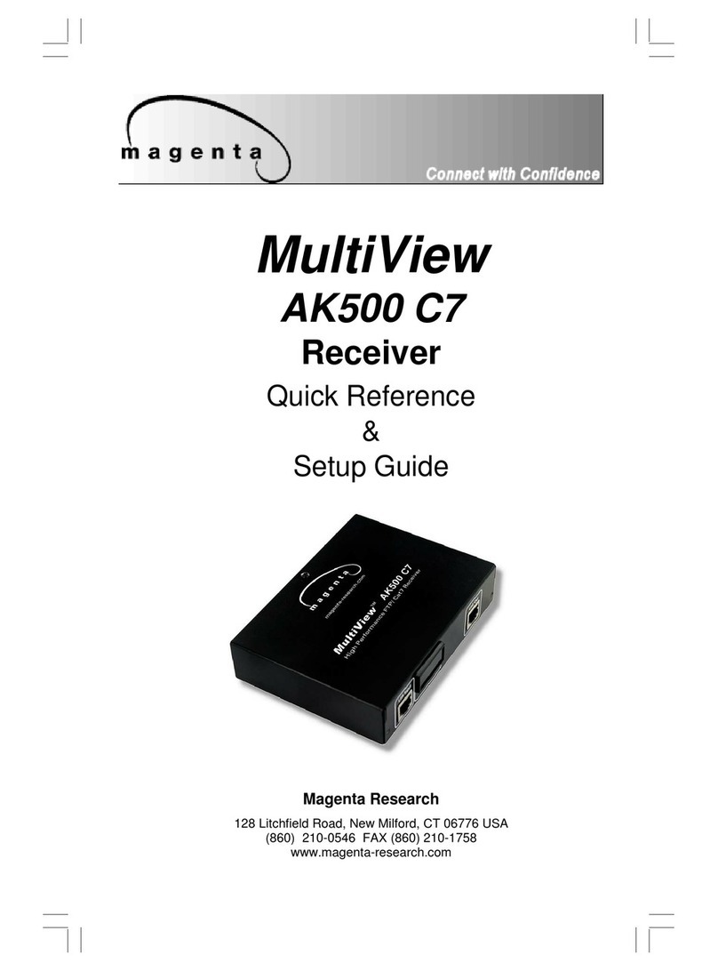
Magenta MULTIVIEW 250A User manual

Magenta Research
934 Federal Road, Brookfield, CT 06804 USA
(203) 740-0592 FAX (203) 740-0596
www.magenta-research.com
MultiView
250A
Receiver
Quick Reference
&
Setup Guide
Magenta Research
934 Federal Road, Brookfield, CT 06804 USA
(203) 740-0592 FAX (203) 740-0596
www.magenta-research.com

12
FCC/IC RFI STATEMENTS, EU DECLARATION OF CONFORMITY
FEDERAL COMMUNICATIONS COMMISSION
AND
INDUSTRY CANADA
RADIO FREQUENCY INTERFERENCE STATEMENTS
This equipment generates, uses, and can radiate radio-frequency energy, and if
not installed and used properly, that is, in strict accordance with the manufacturer’s
instructions, may cause interference to radio communication. It has been tested
and found to comply with the limits for a Class A computing device in accordance
with the specifications in Subpart B of Part 15 of FCC rules, which are designed to
provide reasonable protection against such interference when the equipment is
operated in a commercial environment. Operation of this equipment in a
residential area is likely to cause interference, in which case the user at his own
expense will be required to take whatever measures may be necessary to correct
the interference.
Changes or modifications not expressly approved by the party responsible
for compliance could void the user’s authority to operate the equipment.
This digital apparatus does not exceed the Class A limits for radio noise emission
from digital apparatus set out in the Radio Interference Regulation of Industry
Canada.
EUROPEAN UNION DECLARATION OF CONFORMITY
The manufacturer declares that this product meets the requirements of
EU Directive 89/336/EEC.
1
.
1
Contents
Chapter Page
1. Specifications...................................................................................................3
2. Introduction ........................................….........................................................4
2.1 Overview................................................................................….................4
2.2 Equipment You May Also Need..........................................................…....4
2.3 Compatible Cabling ........................................................................…...….4
3. Setup and Installation.......................................… ......................................….5
3.1 Cabling Considerations.................................................................................5
3.2 Making the Connections.....................................................................…......5
3.2.1 Connections and Setup in General .......................................……......5
3.2.2 Connections on the Single-Port VGA/Audio……..............………..…..6
3.2.3 Connections on the T4 VGA/Audio Transmitter…………….…....……7
3.2.4 A Typical Single-Port Transmitter–Receiver Application .....…....…...7
3.2.5 A Typical Quad T4 Transmitter–Receiver Application…........….…….8
3.3 Configuration Settings..................................…..................................……....9
3.4 Video Adjustment……..................................…...................................……...9
4. Troubleshooting..............................................................................................10
4.1 Common Problems .....................................................................................10
Appendix A. Cabling Pinouts.........................................….....................................11
2

2
1.Specifications
Cable Required: Category 5, 5e, 6 shielded or unshielded twisted pair
Compliance: CE; FCC Class A, IC Class/class A
Video Support: to UXGA (1600x1200 @ 70Hz), RGBHV, RGB, Composite, S-
Video, Component Video modes
Maximum
Resolution and
Refresh Rate: At 250 ft. (76 m) or less, 1600 x 1200 at 70 Hz
Required Source
Impedance: Video OUT: 75 ohms;
Audio OUT (if any): 600 ohms maximum
Required Destination
Impedance: Video IN: 75 ohms;
Audio IN (if any): 600 ohms minimum
Audio
Characteristics: Channels: Right/Left summed;
Line Level 600 Ohm Unbalanced
Connectors: (1) 3.5-mm, (1) RJ-45, (1) HD15 F
Temperature
Tolerance: Operating: 32 to 104°F (0 to 40°C);
Storage: -4 to +140°F (-20 to +60°C)
Humidity
Tolerance: Up to 80% noncondensing
Enclosure: Steel
Power: +5 VDC @ 260 mA max
Consumption: 1.3 watts maximum
Size: 0.88 "H x 3.12"W x 3.75"D (2.2 x 7.9 x 9.5 cm)
Weight: 0.56 lb. (0.26 kg)
CHAPTER 1: Specifications
3
.
114
2. Introduction
2.1 Overview
Magenta’s MultiView™CAT5 Video System MultiView series extends VGA and
audio signals over ordinary Category 5 cable.
This manual covers the Magenta MultiView™250A CAT5 Video System Series
Receiver with Audio.
For information on the respective transmitter unit, please refer to the appropriate
manual included with the transmitter.
WARNING
This equipment is not intended for, nor does it support, distribution
through an Ethernet network. Do not connect these devices to any sort
of networking or telecommunications equipment!
2.2 Equipment You May Also Need
• 1/8” (3.5mm) Audio cable with RCA jacks.
• Video cable with HD15 connectors.
• CAT5 cable.
2.3 Compatible Cabling
CAT5 cabling for the MultiView™Series must be pinned to the T568B wiring
specification (see appendix A). We also highly recommend that all CAT5 cables
be pre-terminated and tested. Cables terminated on-site or in an existing
infrastructure should be tested before use to ensure compliance with the T568B
specification. Using incorrectly terminated CAT5 cables can damage the Magenta
MultiView™Series.

105
CHAPTER 3: SETUP & INSTALLATION
3. Setup and Installation
3.1 Cabling Considerations
• We recommend mounting and connecting all cabling to the MultiView™Series
components before applying power.
• Make sure that the CAT5 cable you intend to use has been tested to comply
with the T568B wiring specification (See Appendix A).
3.2 Making the Connections
3.2.1 CONNECTIONS AND SETUP IN GENERAL
This section contains figures showing connections with the specific MultiView™
Series models. In general, however, the connection and setup procedure at both
transmitter and receiver ends is as follows:
At the transmitter end (refer to the transmitter user guide) :
1. Connect the source video to the MultiView™Series transmitter video input port,
which is an HD15 connector labeled SOURCE IN.
2. If desired, attach a local monitor via the local monitor port to LOCAL OUT.
3. Make your audio connections via the 1/8” (3.5mm) audio connector or phoenix
connector (transmitter model dependent).
4. Connect the CAT5 cable to the transmitter.
5. Apply power on the transmitter. The LED should light and, if there’s a local
monitor attached, a video image should appear on the monitor’s screen.
At the receiver end:
1. Connect the VIDEO OUTPUT HD15 connector to the display unit and attach
any audio cabling.
2. Connect a 1/8” (3.5mm) audio cable to the AUDIO OUTPUT connection.
3. Connect the CAT5 cable to the UTP INPUT connection.
4. Apply power. The LED should light and video should appear on the display
(make sure display is powered ON).
5. To adjust video levels see Section 3.4.
.
3
3.2.2 CONNECTIONS ON THE SINGLE-PORT VGA/AUDIO TRANSMITTER
The single-port units with audio support video and audio signals over CAT5 cable.
The audio signal is line-level audio, and powered speakers are required. Figure 3-1
shows the MultiView™Series UTx transmitter with Audio Transmitter connections,
and Figure 3-2 shows the MultiView™MV250A receiver connections.
Figure 3-1. Transmitter connections on the UTx Universal Transmitter.
Figure 3-2. Receiver connections on the MultiView 250A.
6

4
3.2.3 CONNECTIONS ON THE VGA/AUDIO MULTIVIEW T4
TRANSMITTERS
The MultiView T4 four-port transmitter is used when
the same signal is distributed to multiple display
devices. You set it up and cable it the same as you
would with the single-port transmitter.
3.2.4 A TYPICAL SINGLE-PORT TRANSMITTER–RECEIVER APPLICATION
Figure 3-4 shows a typical application in which the single-unit transmitter
is connected over
CAT5 to a receiver.
Figure 3-3. T4 Transmitter
connections with audio
CHAPTER 3: Setup and Installation
Figure 3-4. Transmitter to Receiver connections.
7
.
9
3.2.5 A TYPICAL MULTIVIEW T4 TRANSMITTER–RECEIVER APPLICATION
Figure 3-5 shows an application in which a MultiView™Series T4 Transmitter is
linked to four MultiView™Series Receivers.
Figure 3-5. MultiView T4 Transmitter to Receiver connections.
8

8
CHAPTER 3: Setup and Installation
3.3 Configuration Settings
The MultiView™250A receiver is configurable for various video and audio modes. Note that a
compatible transmitter unit must be used at the source end. Reference the appropriate transmitter
user guide or call for technical assistance.
A dipswitch on the receiver unit is used to set the video and audio configuration mode. Table 3-1
below shows the configuration settings for SW1 (ON = down, OFF = up)::
NOTE:
There are no user serviceable parts inside the MultiView 250A receiver. All adjustments are
performed externally.
*AV mode carries all signals on the 15HD Video Output connector.
See Appendix A for pinouts
Table 3-1. MultiView 250A Receiver Configuration Settings.
3.4 Video Adjustment
The only adjustments required on the MultiView 250A receiver are the SW1 positions 4 and 5
which must be set to compensate for cable length. Using the table below as a guide, turn SW1
positions ON or OFF for best picture clarity (ON = down, OFF = up):
Table 3-2. Cable Length EQ Settings.
Cable distance EQ settings
SW1 position 4 5
Short (0-75 ft) OFF OFF
Medium (75-150 ft) ON OFF
Long (150-250 Ft) OFF ON
SW1 Configuration Settings
SW1 position 1 2 3
Signal Setting
L/R Audio On ON ON
Off OFF OFF
Video RGBHV ON
Composite OFF
S-Video OFF
AV Mode Composite
+ Stereo Audio*
OFF OFF OFF
Component OFF
9
.
5
4. Troubleshooting
4.1 Common Problems
In most cases, nearly every issue with the MultiView™Series can be resolved by
checking the CAT5 termination and making sure that it’s pinned to the
568B wiring specification. However, there may be other problems that cause the system
to not perform as it’s designed. Below are solutions to the most common installation
errors.
Problem: No video signal at the transmitter local port or at the receiver.
Solution: • Check that both units are powered.
• Ensure Cable Length Compensation Switches are set
correctly (See Section 3-4).
• Make sure the CAT5 cable is terminated correctly per the
568B wiring specification.
• Is the display device powered on and functioning?
Problem: Poor video quality.
Solution: • Have all receiver adjustments been finished (see section 3.4).
• Check all cable connections.
• Ensure Cable Length Compensation Switches are set
correctly (See Section 3-4).
• The video signal’s refresh rate may be set too high for the display.
Reset to a lower refresh rate in your monitor-configuration menu.
Problem: Poor audio quality.
Solution: • Powered speakers are required. Make sure speaker power is
ON.
• Check input source levels from the source device. Make sure
the audio source is not overdriven or underdriven.
Problem: “Green shift” or “green washout” on multimedia signals.
Solution: The standard video model is designed to function with DC
coupled signals in which the black level is referenced to 0 volts.
Nearly all VGA cards function this way.
Some media servers and inexpensive VGA DA’s, however, provide
AC coupled signals and can cause a green color shift in the video.
This is a result of the sync clamping on the red and blue channels of
the video/serial model.
For five-component (RGB/H&V) AC coupled video, the
MultiView™Series UTx Universal transmitter
has been designed with full DC restoration capability. This
problem is easily solved via a simple switch setting in the UTx
Transmitter. Please refer to the UTx Transmitter user manual.
10

6
APPENDIX A: Cabling Pinouts
Appendix A. Cabling Pinouts
Table A-1. HD15 video connector.
Pin RGBHV
(VGA)
RGBS RGsB Com-
posite
SVHS
(Y/C)
YUV Composite
Video
& Stereo
Audio
1 Red + Red + Red + C+ V+ Audio Left
2 Green+ Green+ Green+ C+ Y+ Y+ C+
3 Blue+ Blue+ Blue+ U+ Audio Left
4 — — —
5 Gnd Gnd Gnd
6 Red- Red- Red- C- V- Shield
7 Green- Green- Green- C- Y- Y- C-
8 Blue- Blue- Blue- U- Shield
9 — — —
10 Gnd Gnd —
11 Gnd Gnd —
12 — — —
13 H Sync C Sync —
14 V Sync — —
15 Gnd Gnd —
11
.
7
Appendix A. Cabling Pinouts
Table A-2. T568B CAT5 pinout
Table A-3. 1/8” (3.5 mm) Audio Connection
Note: The stereo audio input at the transmitter is summed and output as
mono audio on both channels at the receiver.
Pin Channel 1 Channel 2
Tip +
Ring +
Sleeve - -
12
Table of contents
Other Magenta Receiver manuals

Magenta
Magenta MultiView II AK600 User manual

Magenta
Magenta MultiView II DVI-Rx-1K User manual

Magenta
Magenta MultiView II AK1200 User manual

Magenta
Magenta MULTIVIEW XR2000 User manual

Magenta
Magenta MultiView Series User manual

Magenta
Magenta MultiView II DVI-Rx-1K User manual

Magenta
Magenta MultiView II AK600 User manual

Magenta
Magenta MultiView 500A User manual

Magenta
Magenta MultiView II AK600DP-A User manual

Magenta
Magenta MultiView NEC 600 User manual