manuals.online logo
Brands
  1. Home
  2. •
  3. Brands
  4. •
  5. Magnadyne
  6. •
  7. Antenna
  8. •
  9. Magnadyne RVTV-B2 User manual

Magnadyne RVTV-B2 User manual

This manual suits for next models

1

Other Magnadyne Antenna manuals

Magnadyne RV2458 User manual

Magnadyne

Magnadyne RV2458 User manual

Magnadyne WS-W User manual

Magnadyne

Magnadyne WS-W User manual

Popular Antenna manuals by other brands

DAVIS Windex AV 3160 installation instructions

DAVIS

DAVIS Windex AV 3160 installation instructions

Belden Hirschmann BAT-ANT-N-14G-IP23 Mounting instruction

Belden

Belden Hirschmann BAT-ANT-N-14G-IP23 Mounting instruction

Vtronix YHK Fitting instructions

Vtronix

Vtronix YHK Fitting instructions

KVH Industries TracVision 6 Technical manual

KVH Industries

KVH Industries TracVision 6 Technical manual

Leica Geosystems GS10 user manual

Leica Geosystems

Leica Geosystems GS10 user manual

Sirio Antenne Gain-Master manual

Sirio Antenne

Sirio Antenne Gain-Master manual

Sony VCA-41 Installation/connections

Sony

Sony VCA-41 Installation/connections

ZCG Y100 Series installation guide

ZCG

ZCG Y100 Series installation guide

Advantech Wireless INTREPID120 Assembly instructions

Advantech Wireless

Advantech Wireless INTREPID120 Assembly instructions

Cerio ANT-10AO installation guide

Cerio

Cerio ANT-10AO installation guide

Alfa Network APA-L01 Specifications

Alfa Network

Alfa Network APA-L01 Specifications

Naval PR-422CA Operation manual

Naval

Naval PR-422CA Operation manual

Feig Electronic ID ISC.ANTH200/200 Series manual

Feig Electronic

Feig Electronic ID ISC.ANTH200/200 Series manual

TERK Technologies TV44 owner's manual

TERK Technologies

TERK Technologies TV44 owner's manual

TERK Technologies SIR3 owner's manual

TERK Technologies

TERK Technologies SIR3 owner's manual

Directive Systems & Engineering DSE2324LYRMK quick start guide

Directive Systems & Engineering

Directive Systems & Engineering DSE2324LYRMK quick start guide

HP J8999A instructions

HP

HP J8999A instructions

MobilSat MSP-S Mounting instructions

MobilSat

MobilSat MSP-S Mounting instructions

manuals.online logo
manuals.online logoBrands
  • About & Mission
  • Contact us
  • Privacy Policy
  • Terms and Conditions

Copyright 2025 Manuals.Online. All Rights Reserved.

ON OFF
Satellite
TV 1
ON = TV
OFF = Cable
AM/FM ANTENNA
TV ANTENNA
TV ANTENNA
TV 2
TV 3 CABLE IN
TV 1 TV 2 TV 3
Gasket
Mounting Bolts
Mounting Stand
Locking Nut
Vehicle’s Roof
Mounting Bracket
Washer
Locking Washer
Nut
Cable Input Plate
(Not Supplied)
Distribution Wall Plate (Supplied Separately)
Models: WS-W (White) or WS-B (Black)
Coaxial Cable
(Purchased Separately)
Coaxial Cables
(Purchased
Separately)
Coaxial Cable
(Purchased Separately)
Satellite Antenna
(Not Supplied )
Coaxial Cable
(Purchased Separately)
AM/FM Receiver (Not Supplied)
Red Wire +12V DC
Black Wire Ground
AM/FM ANTENNA
No Connection
(for use with
RVTV-B1 or
RVTV-W1 only)
Models: RVTV-B2 (Black)
RVTV-W2 (White)
1111 West Victoria Street
Compton, CA 90220 www.magnadyne.com © Copyright 2013 Magnadyne For Technical Assistance, please call (800) 638-3600
Installation Instructions
RVTV-X2-IMUM Rev. A 1-7-13
Installation
Step 1: Choosing a Location: Make sure the mounting location has a sufficient
flat area so the antenna’s mounting stand can be mounted flat.
Step 2: Drilling Holes: Use the mounting bracket as a template to determine
where to drill the holes.
Step 3:
Assembling the Antenna: Rotate the antenna’s locking nut all the way down
on the base. Gently pull the antenna’s cables thru the mounting stand. Screw
the antenna onto the mounting stand then rotate up the locking nut to lock
the antenna into place.
Step 4: Attaching the Antenna: Feed the cables thru the gasket then thru the hole
in the roof. Put the mounting bolts thru the holes in the mounting stand.
On the interior, place the mounting bracket then use the washers and nuts
to secure the antenna.
Caution: Do not overtighten the mounting bolts, damage to the mounting
stand or roof may occur.
Step 5: Wiring: Connect the cables from the antenna to distribution wall plate and
to the radio. Connect the power cables from the distribution wall plate
according to the diagram below.
Technical Specifications
Frequency range: VHF: 47-230MHz
UHF: 470-862MHz
Receiving range: FM/VHF/UHF
Gain: 30dB
Noise: 3dB
Maximum output level: 110dBµV
Impedance: 75Ω
Power supply: DC 12V
Antenna Extension
Cable
(Purchased
Separately)
(White)
(Black)
(Blue) (Yellow)
(Black)
RVTV-B2 or RVTV-W2 Antenna
Power
Indicator
Models: RVTV-B2 (Black)
RVTV-W2 (White)
Operating Instructions
Selecting TV Antenna Reception
To receive TV antenna reception press the
On/Off switch so the power indicator is lit.
ON OFF
Satellite
TV 1
ON = TV
OFF = Cable
1111 West Victoria Street
Compton, CA 90220 www.magnadyne.com © Copyright 2013 Magnadyne For Technical Assistance, please call (800) 638-3600
Power
Indicator
Selecting Cable TV
To receive cable TV press the On/Off switch so
the power indicator is off.
Note: The vehicle must be connected to an
external cable source.
ON OFF
Satellite
TV 1
ON = TV
OFF = Cable
1
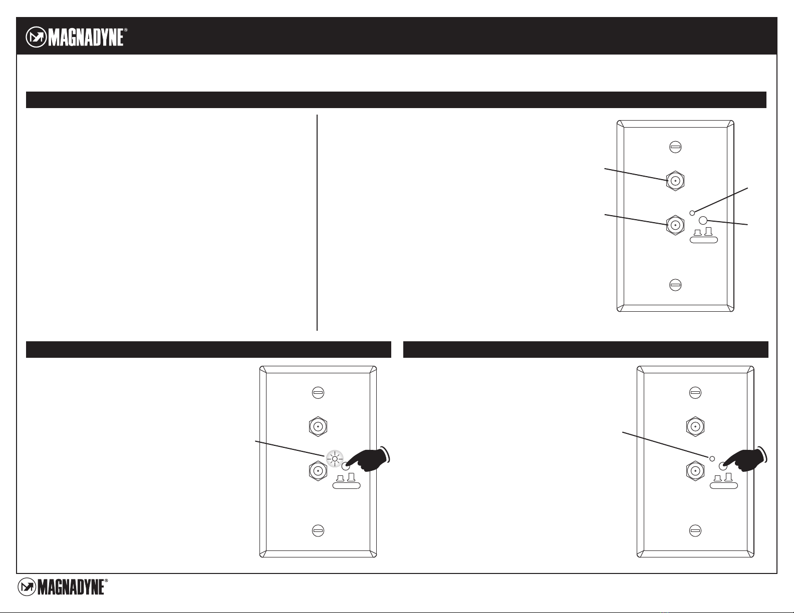
Distribution Wall Plate Features
Features:
• Compatible with HDTV.
• Built-in high gain and low noise amplifier, shielded for minimum
interference.
• Omnidirectional antenna receives VHF, UHF and AM/FM signal from
every point regardless of the direction you are traveling.
• Amplifier with SMD technology and micro-electronics ensures
excellent antenna performance.
• Waterproof antenna made of UV resistant ASA material.
ON OFF
Satellite
TV 1
ON = TV
OFF = Cable
2
3
4
1. Satellite Antenna Output Connector: Use a cable to connect
to a TV to receive a satellite signal.
Note: A satellite antenna must be connected to the vehicle.
2. TV 1 or Cable Output Connector. Use a cable to connect to a
TV to receive either TV antenna or cable reception.
3. TV Antenna Power Indicator. When lit indicates TV reception.
When off indicates cable reception.
4. TV Reception or Cable Selector Switch. Press this button to
choose from TV or cable reception.
Note: Every TV (TV 1, TV 2 and TV 3) connected to the wall
distribution plate will be switch when a selection is made,
either TV or cable.