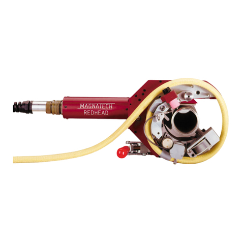
MAGNATECH Pipeliner II 609A Manual

6 Kripes Road - PO Box 260 - East Granby, CT 06026 USA
Phone: (860) 653-2573 Web: www.magnatech-lp.com
Operating and Maintenance
Instruction Manual
For
Pipeliner II Model 609A
Orbital Weld Head
- Wire Feed on Floor (WFOF) version
- Wire Feed on Hand (WFOH version
- Wire Feed Push-pull (WFPP) version
For Use With
MPS 4000 Power Source & Model 712 Controller
(See Separate Manual)
Rev 01-14-2009

TABLE OF CONTENTS
SECTION TITLE PAGE
1.0 INTRODUCTION 1
1.1 Copyright Notice
2.0 PIPELINER IIC COMPONENT INVENTORY 2
2.1 Weld Head 609A
2.2 Guide Rings
2.3 Optional Installed Components/Kits
2.4 Optional Free-Standing (Unattached) Components
3.0 SAFETY INSTRUCTION AND WARNING FOR OPERATION AND ARC
WELDING EQUIPMENT 4
3.1 Important to Read
3.2 Introduction
3.3 Shock Prevention
3.4 Burn Prevention
3.5 Toxic Fume Prevention
3.6 Compressed Gas Cylinder Handling
3.7 Equipment Warning Labels
3.8 Additional Safety and Health Information
4.0 WARRANTY POLICY & SUPPORT 11
4.1 General
4.2 Support
5.0 SPECIFICATIONS 16
5.1 Pipeliner Weld Head
6.0 INSTALLATION 18
7.0 FUNCTIONAL DESCRIPTION - WELD HEAD 19
7.1 Oscillator
7.2 Arc Gap Control (Torch Proximity Control)
7.3 Tractor
7.4 Torch and Cable
7.5 Guide Ring/Flx-Track
8.0 SET-UP AND OPERATION 21
8.1 Mounting the Friction Drive Guide Ring
8.2 Install Weld Head on Guide Ring
8.3 Adjust Head for New Guide Ring Size
8.4 Check Electrical, Gas, and Water Connections
8.5 Training Outline

TABLE OF CONTENTS - CONTINUED
SECTION TITLE PAGE
9.0 USE OF WELD HEAD ON PREHEATED PIPE 28
10.0 ADAPTOR FEET KITS FOR PIPELINER GUIDE RING TO ALLOW 29
USE ON SMALLER PIPE SIZES
11.0 TORCH EXPENDABLE COMPONENTS LIST 32
11.1 For "Binzel" Torch P/N 103364-6
12.0 SUMMARY OF CAUTIONS 33
12.1 Shock Prevention
12.2 Safety and Health Precautions
12.3 Check Electrical Connections
12.4 Prevent Torch Cable Wrap-Up
12.5 Observe Torch Position Before Oscillating or "Centering" Torch
12.6 Always Stop Motors Before Reversing
12.7 Abrasive Grinding Dust Will Cause Premature Wear
12.8 Heat Damage
12.9 Exposure to Rain
12.10 Obstruction of Weld Head Rotation
13.0 WELD PROCESS DEVELOPMENT 35
14.0 ELECTRODE EXTENSION OFTEN NEGLECTED WHEN USING 43
SELF-SHIELDED CORED WIRES
15.0 PREVENTING THE EFFECTS OF MOISTURE CONTAMINATION OF 46
FLUX CORE WIRE
16.0 BILLS OF MATERIALS/DRAWINGS 48
17.0 ELECTRICAL SCHEMATICS 49

1
1.0 INTRODUCTION
The Pipeliner Welding System is designed for mechanized welding applications using
the high-deposition GMAW/FCAW processes for efficient joining. Circular Guide Rings
allow use for pipe-to-pipe and pipe-to-fitting butt welding. Flx-Track allows linear welding
on flat or curved workpieces (ID and OD). A simple adaptor (optional) allows use for
socket and fillet welding applications. An optional pendular torch oscillator is
recommended for fillet applications, and welding pipe with wall thicknesses over 50mm
(2”).
The weld Head is designed to be used with the Pipeliner model 712 Controller, MPS
4000 Power Source and Water Circulator.
This Weld Head is available in three versions:
• Floor mounted wire feeder
• Hand mounted wire feeder
• Push-pull system
This manual covers general operating instructions, as well as assistance in weld
procedure development.
The appropriate interconnect cables and accessories are provided.
When the equipment is first received we recommend that a quick inventory is taken of all
items using the packing list enclosed with the shipment.
ATTENTION:ALL FASTENERS ON THESE WELD HEAD MODELS ARE METRIC
1.1 COPYRIGHT NOTICE
This manual and the information contained herein is the property of Magnatech
Limited Partnership. It is proprietary and shall not be copied in whole or in part
without the prior express written permission of Magnatech Limited Partnership.
Information and instructions in this document are subject to change and
Magnatech Limited Partnership reserves the right to change specifications and
data without notice.
This documents is based on the latest design version at the time of publication.
Some deviations in actual operation, from this document, are possible depending
on the production generation of a particular machine.
Edition publication date – April 2007. Copyright 2007 by Magnatech Limited
Partnership. All rights reserved.

2
2.0 PIPELINER IIC COMPONENT INVENTORY
Each model comes equipped with the following components:
2.1 WELD HEAD 609A S/N _________________________
1Pipeliner II Weld Head Model 609A (WFOF)609AF0AWC0
Floor-mounted Feeder with Pneumatic
Mounting and Pendular Oscillation Option
1 - Weld Head - 103951-PD
1 - Torch Cable - 103090-15-PD
1 - Accessories Kit - 104017-1
1 - Dual Regulator - 38416
1 - Operation Manual - Manual
1Pipeliner II Weld Head Model 609A (WFOF)609AF0A0C0
Floor-mounted Feeder with Pneumatic
Mounting
1 - Weld Head - 103951-P
1 - Torch Cable - 103090-15-P
1 - Accessories Kit - 104017-1
1 - Dual Regulator - 38416
1 - Operation Manual - Manual
1Pipeliner II Weld Head Model 609, 609AGEB0CP
Pneumatic Mounting, w/Push Pull Wire
Feeder (WFPP)
1 - Weld Head - 103951-P
1 - Torch Cable - 103364-25-P
1 - Wire Drive Kit - 104022-1
1 - Accessories Kit - 104017-1
1 - Dual Regulator - 38416
1 - Operation Manual - Manual
1Pipeliner II Weld Head Model 609A, 609AGEB0C9
Pneumatic Mounting, 2-Roll Head-
Mounted Feeder (WFOH)
1 - Weld Head - 103951-P
1 - Torch Cable - 103364-25-P
1 - Wire Drive Kit - 104022-1
1 - Accessories Kit - 104017-1
1 - Dual Regulator - 38416
1 - Operation Manual - Manual

3
1Pipeliner II Weld Head Model 609A, 609AGEBWC9
Pneumatic Mounting, 2-Roll Head-
Mounted Feeder (WFOH), 25' (8m)
Torch Cable
1 - Weld Head - 103951-PD
1 - Torch Cable - 103364-25-P
1 - Wire Drive Kit - 104022-1
1 - Accessories Kit - 104017-1
1 - Dual Regulator - 38416
1 - Operation Manual - Manual
1Pipeliner II Weld Head Model 609A, 609AGEC0C9
Pneumatic Mounting, 2-Roll Head-
Mounted Feeder, 50' (15m)
Torch Cable, (WFOH)
1 - Weld Head - 103951-P
1 - Torch Cable - 103364-50-P
1 - Wire Drive Kit - 104022-1
1 - Accessories Kit - 104017-1
1 - Dual Regulator - 38416
1 - Operation Manual - Manual
1Pipeliner II Weld Head Model 609A, 609AGECW9
Pneumatic Mounting, 2-Roll Head-
Mounted Feeder, 50' (15m) Torch
Cable w/Pendular Oscillator (WFOH)
1 - Weld Head - 103951-PD
1 - Torch Cable - 103364-50-PD
1 - Wire Drive Kit - 104022-1
1 - Accessories Kit - 104017-1
1 - Dual Regulator - 38416
1 - Operation Manual - Manual
2.2 GUIDE RINGS
1103040-XXXXX Guide Ring Assembly - Friction Drive
A/R103070-XXXX Adaptor Foot Set - Guide Ring Radial Extension
2.3 OPTIONAL INSTALLED COMPONENTS/KITS:
1103190-1Torch Axial Slide Assembly - MIG (For Socket Welding)
2.4 OPTIONAL FREE-STANDING (UNATTACHED) COMPONENTS:
1103408-50Extension Cable 15m (50’)

4
3.0 SAFETY INSTRUCTION AND WARNING FOR OPERATION AND ARC WELDING
EQUIPMENT
3.1 IMPORTANT: The nature of the GMAW process creates some potential
hazards. In accordance and compliance with the international safety regulations,
the "exclamation symbol" indicates that this equipment is to be considered
"Hazardous" UNTIL an operator has been made aware of these potential
hazards by READING THIS MANUAL. The "lightening flash" symbol indicates
that there are potential electrical hazards. The display of these symbols make it
the OPERATOR'S RESPONSIBILITY TO INSURE THAT HE HAS READ
AND/OR BEEN MADE AWARE OF ALL OF THE SAFETY RELATED ITEMS
CONTAINED IN THIS MANUAL.
READ AND UNDERSTAND THESE INSTRUCTIONS BEFORE INSTALLING,
OPERATING OR SERVICING MAGNATECH EQUIPMENT OR AUXILIARY
EQUIPMENT SUPPLIED AS PART OF THE WELDING SYSTEM.
3.2 INTRODUCTION
Welding products and welding processes can cause serious injury or death, and
possible damage to other equipment if the operator does not strictly observe all
safety rules and take precautionary actions.
Safe practices have developed from past experience in the use of welding and
cutting. These practices must be learned through study and training before using
this equipment. Anyone not having extensive training in welding practices should
not attempt to weld.
Safe practices are outlined in the American National Standard Z49.1 entitled:
SAFETY IN WELDING AND CUTTING. This publication and other guides to
what you should learn before operating this equipment are listed later in this
section.
3.3 SHOCK PREVENTION
Bare conductors, or terminals in the output circuit, or ungrounded, electrically-live
equipment can fatally shock a person. To protect against shock, have a
competent electrician verify that the equipment is adequately grounded. Do not
make contact with terminals and parts that are electrically HOT.
The body's electrical resistance is decreased when wet, permitting dangerous
!W
W
A
A
R
R
N
N
I
I
N
N
G
G!
Read Before Proceeding

5
currents to flow through the body. Do not work in damp area without being
extremely careful. Stand on dry rubber mats or dry wood and use insulating
gloves when dampness or sweat cannot be avoided. Keep clothing dry.
3.3.1 Installation and Grounding of Electrically Powered Equipment
Electrical equipment must be installed and maintained in accordance with the
National Electrical Code, NFPA 70, and local codes. A power disconnect switch
must be located at the equipment. Check equipment nameplates for voltage and
phase requirements. If only 3-phase power is available, connect single-phase
equipment to only two wires of the 3-phase line. DO NOT CONNECT the
equipment grounding conductor (lead) to the third live wire of the 3-phase line as
this makes the equipment frame electrically HOT, which can cause fatal shock.
If a grounding lead (conductor) is part of the power supply cable, be sure to
connect it to a properly grounded switch box or building ground. If not part of the
supply cable, use a separate grounding lead (conductor). Do not remove a
ground prong from any plug. Use correct mating receptacles. Check ground for
electrical continuity before using equipment.
3.3.2 Torch and Work Cables
Inspect cables often for damage to the insulation. Replace or repair
cracked or worn cables immediately. Do not use a welding current in
excess of rated cable capacity, as the cable will overheat.
3.3.3 Power Source Output Terminals
The Fronius TPS-450 Power Source completely shields the output
terminals when the Torch and Ground Cables are connected.
3.3.4 Service and Maintenance
Shut OFF all power at the disconnect switch or line breaker before
inspecting or servicing the equipment. Unplug the input power cord. If the
equipment is wired directly to an electrical box. lock the switch OFF (or
remove line fuses) so that power cannot be turned ON accidentally.
Disconnect power to equipment if it is to be left unattended or out of
service.
3.3.5 Fuses and Circuit Breakers
Replace fuses and circuit breakers with equivalent sizes.
3.4 BURN PREVENTION
The welding arc emits high energy radiation in the infrared and ultraviolet range.
This energy penetrates lightweight clothing and is reflected from light-colored
surfaces. The arc rays can injure the eyes permanently and burn the skin, just
as in "sunburn". Never look at an electric arc without eye protection.

6
3.4.1 Protective Clothing
Wear gloves, suitable long sleeved shirts/jackets, safety shoes, welding
helmet, and other articles needed to shield the skin and to prevent injury
from arc burns. Wear ear plugs if welding overhead or in a confined
space. Wear a hard hat if others are working above you.
3.4.2 Eye and Head Protection
Protect your eyes and head by wearing a welding helmet fitted with a
double lens; use a clear lens outside and a colored, welding filter inside.
Use at least a number 10 filter. If welding over 100 amps, use a number
12 filter (or darker as appropriate).
Always lower the helmet before striking the arc. Wear safety glasses with
side shields under the helmet to protect the eyes from flying particles and
side arc flashes when the helmet is up.
Protect the eyes of other people in the area by use of opaque, non-
reflecting and nonflammable screens around your welding station. Allow
good air circulation, especially at floor level. Do not permit anyone to
view the arc unless he uses a correct hand shield, or helmet.
3.5 TOXIC FUME PREVENTION:
Breathing the fumes created during welding or cutting can cause illness or death
if adequate ventilation is not provided. Provide ventilation in accordance with
ANSI Standard Z49.1.
Some Fume Sources are:
3.5.1 Weldments
Metals containing lead, cadmium, zinc, mercury and beryllium can
produce harmful toxic fumes when welded or cut. Adequate local exhaust
ventilation must be used for the operator and persons in the area.
3.5.2 Coated Weldments
Remove coatings that emit toxic fumes when heated or use exhaust
ventilation and/or an air-supplied respirator.
3.5.3 Vessels That Have Contained Toxic Materials
Vapors from chlorinated solvents can be decomposed by the arc to form
the highly toxic gas called PHOSGENE or other damaging products. The
ultraviolet radiant energy of the arc can also decompose trichloroethylene
and perchloroethylene vapors to form PHOSGENE. Do not weld or cut
unless such containers have been thoroughly cleaned following AWS
Standard A6.0.

7
3.5.4 Welding Area
Do not weld in locations close to chlorinated vapors coming from
degreasing, cleaning or spraying operations. The heat and rays from the
arc react with the vapors to form highly toxic PHOSGENE. Work in a
confined space only if it is being adequately ventilated, and if ventilation is
not adequate, wear an air-supplied respirator (see ANSI 2.37).
3.6 COMPRESSED GAS CYLINDER HANDLING:
Follow precautions below and those outlined in CGA Standard P-1, Precautions
For Safe Handling Of Compressed Gases in Cylinders.
3.6.1 Cylinders
Handle carefully to prevent damage. Keep away from welding cables or
other electrical circuits. Use only cylinders with name of gas marked on
them; DO NOT rely on color identification. Close valves on empties and
return promptly. Secure cylinders so they cannot be knocked over. Keep
temperature below 130 degrees F.
3.6.2 Pressure Regulators
Use the correct regulator for the gas and cylinder at hand. Remove any
suspected faulty regulator and return to manufacturer's service center for
repair.
3.7 EQUIPMENT WARNING LABELS:
Inspect all precautionary labels on the equipment.
3.8 ADDITIONAL SAFETY AND HEALTH INFORMATION:
3.8.1 ANSI Standard Z49.1, SAFETY IN WELDING AND CUTTING. Order
from the American Welding Society, P. O. Box 351040, 550 N. W.
LaJeune Road, Miami, FL 33125.
3.8.2 ANSI Standard Z87.1, SAFE PRACTICE FOR OCCUPATION AND
EDUCATIONAL EYE AND FACE PROTECTION. Order from American
National Standards Institute, 1430 Broadway, New York, NY 10018.
3.8.3 ANSI Standard Z241.1, Standard for Men's Safety-Toe Footwear. Order
from same as item 2.
3.8.4 American Welding Society Standard F4.1-80, WELDING AND CUTTING
CONTAINERS WHICH HAVE HELD COMBUSTIBLES. Order same as
for Item 1.
3.8.5 OSHA Standard 29 CFR, Part 1910, Subpart Q, WELDING, CUTTING
AND BRAZING. Order from Superintendent of Documents, U.S.

8
Government Printing Office, Washington, DC 20402.
3.8.6 NFPA Standard 51B. CUTTING AND WELDING PROCESSES. Order
from the National Fire Protection Association, Batterymarch Park, Quincy,
MA 02269.
3.8.7 CGA Pamphlet P-1, SAFE HANDLING OF COMPRESSED GASES IN
CYLINDERS. Order from the Compressed Gas Association 1235 Jeff
Davis Highway, Arlington, VA 22202.
3.8.8 CSA Standard W117.2, CODE FOR SAFETY IN WELDING AND
CUTTING. Order from Canadian Standards Association, 178 Rexdale
Boulevard, Rexdale, Ontario, Canada M9W 1R3.

9

10

11
4.0 WARRANTY POLICY & SUPPORT
4.1 General:
Magnatech warrants equipment that it manufactures to be free from defects from
material and workmanship under normal use and service for the periods defined
below. This Warranty shall apply to the Original Purchaser only, and is not
transferable. All warranty time periods start on the date that the equipment was
delivered to the original retail purchaser. Our sole obligation under this warranty
is limited to repairing or replacing the defective part or parts, which in our
judgment show evidence of such defects. All warranty repair work shall be
accomplished at the factory and Magnatech assumes no obligation to perform
warranty service at a customer's facility. If requested, Magnatech shall supply
warranty parts for customer installation, but reserves the right to request the
return of parts declared defective. This warranty is given in lieu of and to the
exclusion of any and all other warranties, express or implied. Specifically, and
without limiting the generality of the above disclaimer, Magnatech disclaims any
warranty of merchantability or fitness for any particular purpose as to any and all
goods sold to the Buyer (whether for the ultimate use of the Buyer, or any other
person) pursuant to the purchase order, contract or in connection therewith.
See Detailed Warranty Terms and Magnatech's General Terms and Conditions.

MAGNATECH LIMITED WARRANTY
Effective November 2008
GENERAL:
Magnatech warrants equipment that it manufactures to be free from defects from material and workmanship under normal use and service for
the periods defined below. This Warranty shall apply to the Original Purchaser only, and is not transferable. All warranty time periods start on
the date that the equipment was delivered to the original retail purchaser. Our sole obligation under this warranty is limited to repairing or
replacing the defective part or parts, which in our judgment show evidence of such defects. All warranty repair work shall be accomplished at
the factory and Magnatech assumes no obligation to perform warranty service at a customer's facility. This warranty is given in lieu of and to the
exclusion of any and all other warranties, express or implied. Specifically, and without limiting the generality of the above disclaimer, Magnatech
disclaims any warranty of merchantability or fitness for any particular purpose as to any and all goods sold to the Buyer (whether for the ultimate
use of the Buyer, or any other person) pursuant to the purchase order, contract or in connection therewith.
COVERED COMPONENTS:
A. 1 Year – Parts and Labor
All Magnatech Power Sources/ Controllers
All Model Water Circulators (with exception of Pump)
All Weld Heads
B. 6 months
Switches
C. 3 months – Parts and Labor
Torch cable assemblies
Relays
Batteries
EXCLUDED COMPONENTS:
Magnatech Limited Warranty shall not apply to:
1. Equipment Supplied Not Manufactured By Magnatech
With respect to standard equipment supplied by Magnatech as part of a complete welding system, Magnatech extends the same warranty as
offered by the individual manufacturer of this standard equipment if any. In many instances such items are warranted directly by the
manufacturer, and Magnatech may, from time to time, inform the customers of such warranty coverage; however, Magnatech does not
guarantee the accuracy of completeness of its information regarding such warranties.
2. Expendable Items
This warranty does not cover certain items considered expendable and certain high wear items offered herein. Expendable items consist of
welding torch components, wire feed conduits, motor brushes, fuses, bulbs and filters.
3. Modification And Misuse
This warranty does not apply to products which have been modified in any way by any party other than Magnatech; nor to products which
have not been installed and operated in accordance with applicable industry standards; or to products which have been used other than
under usual conditions for which they are designed; nor to products that have not received proper care, protection and maintenance under
supervision of competent personnel.
UTILIZATION FOR INTENDED PURPOSE ONLY:
The Tubemaster, Pipemaster, and Pipeliner systems are intended to be used SOLELY for GTAW or GMAW/FCAW orbital welding applications.
Any other use is deemed to be “not for the intended purpose” and the manufacturer shall not be liable for any damage resulting there from.
Utilization for the intended purpose includes:
•observance of all instructions in the operating manual
•performance of all prescribed inspection and maintenance work
Magnatech products are intended for purchase and use by commercial/industrial users and persons trained and experienced in the use and
maintenance of welding equipment.
PERFORMANCE OF WARRANTY REPAIRS – LOCATION:
Magnatech’s obligation under this warranty shall be limited to the repair or replacement, at its option, of any goods or any components or parts
thereof sold by Magnatech to Buyer that prove to be defective upon Magnatech’s examination. Returned goods shall be delivered F.O.B.
Magnatech’s plant, East Granby, Connecticut, at Buyers risk and expense.
DISCLAIMER:
Magnatech shall not be otherwise liable for any damages including but not limited to incidental damage, consequential damage, or special
damages, whether such damages result from negligence, breach of warranty, or the result of repair and replacement activity, including, but not
limited to any losses due to downtime or loss of use. Magnatech shall not be held liable for any lost profit or other damage, delay or loss which
may result directly or indirectly from the adjustment, alteration, repair, maintenance, operation, or interruption thereof, of any said equipment.
There are no warranties of fitness for any particular purpose of said equipment or any other warranties (expressed, implied or statutory)
concerning the performance capabilities thereof. Magnatech shall not be liable for any consequential, indirect or incidental losses or damages
incurred as the result of any breach of warranty or as a result of any repair or replacement activity, including, but not limited to any losses due to
down time or loss of use. Magnatech shall not be liable for any losses, injuries or damages sounding in tort, whether for the negligence of
Magnatech or its agents, officers or employees or in a strict liability theory.
To the extent permitted by law, the remedies provided herein are the sole and exclusive remedies. In no event shall Magnatech be liable for
direct, indirect, special incidental or consequential damages (including loss of profit), whether based on contract, tort, or any legal theory.
Any express warranty not provided herein and any implied warranty guaranty or representation as to performance, and any remedy for breach of
contract tort or any other legal theory which, but for this provision might arise by implication, operation of the law, custom of trade or course of
dealing including any implied warranty of merchantability or fitness for particular purpose, with respect to any and all equipment furnished by
Magnatech is excluded and disclaimed by Magnatech.

13
MAGNATECH PRODUCT WARRANTY REGISTRATION
Please provide the following information and mail/fax to Magnatech. This will allow us to insure correct
replacement parts are supplied, service bulletins reach the correct person, and provide a contact person for
service.
Product Name:
S/N:
Product Name:
S/N:
Product Name:
S/N:
Product Name:
S/N:
Company Name:
Company Address:
Dealer:
Date Purchased
Individual Purchasing:
Name:
Address:
Phone:
Fax:
E-Mail:
Individual to Be Contacted about Upgrades, Service Issues:
Name:
Address:
Phone:
Fax:
E-Mail:
PO Box 260, 6 Kripes Rd
East Granby, CT 06026 USA
T: (860)653-2573
F: (860)653-0486
info@magnatech-lp.com
www.magnatech-lp.com
MAGNATECH Limited Partnership
Orbital Welding Systems
for your Industrial Revolution

14
Magnatech Ltd. Partnership
P. O. Box 260
East Granby, CT 06026
Magnatech Limited Partnership
Attn: Sales Dept.
P. O. Box 260
East Granby, CT 06026
Affix
Postage

15
4.2 Support:
Now that you have purchased a Magnatech product, we want to confirm that we
intend to support you after the sale with the expedient service and technical
support which we strive to maintain at world-class standards.
A. Sales
U.S. Headquarters:
Tel: (860) 653-2573
Fax: (860) 653-0486
John Emmerson - President, Ext. 10
Ken LeDuc - Technical Specialist, Ext. 15
Bryan Kirkland - Sales Order Administration, Ext. 14
Glen Gautieri - Quoting, Ext. 37
Reta Holt - Exec. Asst., Ext. 10
Europe, Middle East, India:
Tel: +(31) 321-38-6677
Fax: +(31) 321-31-4165
W. Wijnholds - Cell +31 (653) 32 5818
Ralph Wijnholds - Cell +31 (653) 548891
B. Spare Parts
Bryan Kirkland - Spare Parts, Ext. 14
C. Service Support (U.S.)
Dave Richard, Vice Pres. - Chief Elect. Eng., Ext. 19
Ted Kingsley - Chief Mechanical Engineer, Ext. 24
Patrick Sweeney - Embedded Systems Eng., Ext. 36
Neil Young - Senior Weld Technician, Ext. 28
Ken LeDuc - Technical Specialist, Ext. 15
D. Welding Development Assistance/Problem Solving
Neil Young - Senior Weld Technician, Ext. 28
Ken LeDuc - Technical Specialist, Ext. 15
E. Accounting (U.S.)
Glen Gautieri - A/R, Ext. 37
John Rinaldi - A/P, Bookkeeping, Ext. 12

16
5.0 SPECIFICATIONS:
5.1 SPECIFICATIONS PIPELINER WELD HEAD
APPLICATIONS
Pipe Size: 6" pipe (168mm) and larger
Guide Rings: For 6" pipe (168mm) and larger
Wall Thickness: Wall Thickness: Unlimited
Pipe Material: All materials which can be welded with GMAW or
FCAW process.
Linear and Large Diameter Flx-Tracks available.
Applications:
FILLER WIRE MODULE
Wire Size 0.8/0.9/1.0/1.2mm (.030/.035/0.040/.045")
Other sizes available.
Speed Capability 0 - 22m/min. (0 - 722”/min.)
Spool Size 4.5 - 5 kg (10 lb) – Wire Feed on Head
or
12kg (25lb) Wire Feed on Floor and Push-Pull
OSCILLATION MODULE
Oscillation Stroke Amplitude: 51mm (2")
Oscillation Speed: 21.4cm/minute (0-100 IPM)
Oscillation Dwell: 0-1.0 second independently adjustable at either
oscillation stroke endpoint.
Cross Seam Adjustment: 51mm (2") Standard
TORCH ARC LENGTH – (VERTICAL MOTION)
Stroke: 66mm (2.6") (motorized)
Torch Advance/Retreat 152cm (60")
(Correction Speed) per minute maximum.

17
TORCH PROPULSION MODULE 0-76cm/minute (0-30 IPM)
Clutch allows rapid repositioning of weld Head.
WATER-COOLED TORCH 300 amps at 100% duty cycle.
TORCH CABLE LENGTH WFOF -4.6M (15’)
WFOH-1.5M(50’)
WFPP-8m (25’)
Extension cables available.
WELD HEAD DIMENSIONS/WEIGHT
Minimum
Axial Radial Overall
Length Clearance Width
Model A1B2C3Weight
609 37.5cm 24.1cm 41.3cm 26.5 lbs
WFPP 14.75" 9.50” 16.25”
609 38.7cm 24.8cm 30.5cm 9.5 kg
WFOF 15.25” 9.75” 12” 21.5 lbs
609 66.7 cm 26.7cm 36.8cm 14.4 kg
WFOH 26.25” 10.5” 14.5” 31.75 lbs
1 Center of oscillation stroke
2 Center of vertical stroke
3 Weight without wire spool (WFOH). Includes 1.6 kg
(3.5) of Torch Cable Weight (Partial)
Guide Rings
Diameter Tolerance: For a 2 segment Guide Ring, the tolerance is +/- 6mm or (+/-
0.25”) on pipe nominal diameter. (This corresponds to 3 mm =/- 0.125” tolerance per
joint X 2.) Each joint adds 3mm (0.125”) to the OD tolerance.
Joints per Diameter:
Two joints: For Guide Rings up to 152 cm (60”)
Three Joints: For Guide Rings up to 231 cm (91”)
Four Joints: For Guide Rings up to 310 cm(122”)
Flx-Track
Minimum/maximum Radius: Workpiece ID/OD must be greater than
2.44 m (8’)
This manual suits for next models
7
Table of contents
Other MAGNATECH Welding Accessories manuals
Popular Welding Accessories manuals by other brands

Ozito
Ozito ADWH-001 instruction manual

ESAB
ESAB PC-900 installation instructions

Lincoln Electric
Lincoln Electric GRAPHICS MAY VARY Operator's manual

Magswitch Technology Inc.
Magswitch Technology Inc. MagSquare Operation and instruction manual

Asist
Asist AR06-1001FL Instructions for use

Edisons
Edisons Rossi WLDCRTROSBD55 Assembly guide