CAR RIDGE OPERA ION/FEA URES
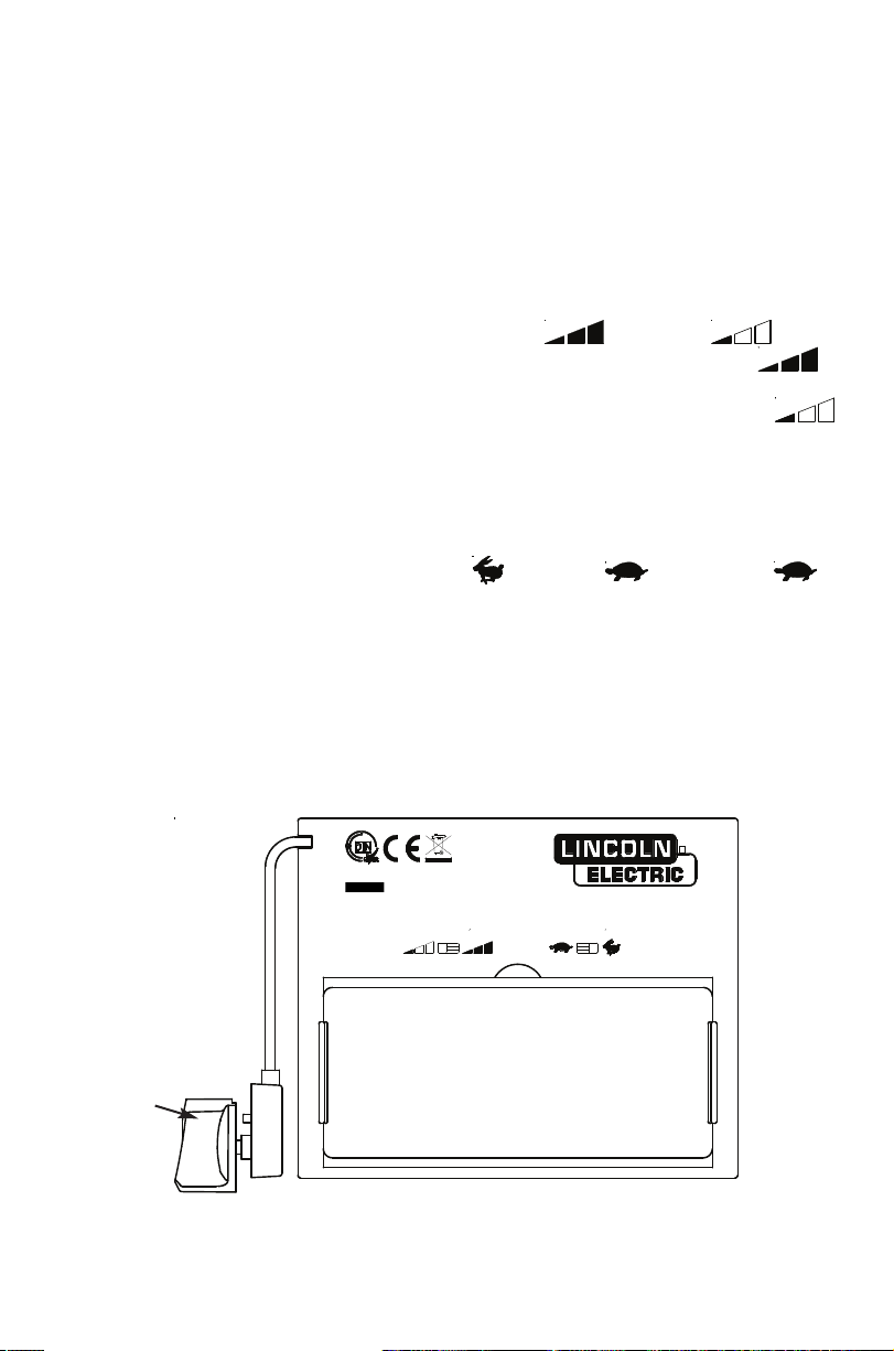
Variable Shade Control
The shade can be adjusted from shade 9 to 13 based upon welding process or
application (refer to Shade selection chart on page 6). The variable shade control
knob is mounted to shell for external adjustment.
Sensitivity Control
You can adjust the light sensor by selecting the (High) or (Low)
position of the sensitivity switch as shown in figure below. Generally, the
(High) setting is selected for normal use. Where the helmet is used in the pres-
ence of excess ambient light or with another welding machine close by, the
(Low) setting may be selected for better performance.
Delay ime Control
This control is designed to protect the welder’s eyes from the strong residual rays
after welding. You can delay the time of change to light state from the darkened
state with setting delay control switch on (Fast) or (Slow). The
(Slow) setting is recommended for high amperage applications where the weld
puddle is still very bright after the welding arc has ceased and for situations
where the filter may be temporarily blocked from seeing the welding arc.
Solar Power
This helmet is powered by solar energy. As such, there is no battery that requires
replacement.
Variable shade
control Knob
5
ALWAYS ES O BE SURE HE ADF CAR RIDGE IS CHARGED
BEFORE WELDING. The helmet can be placed in sunlight to charge. Do
not store the helmet in a dark cabinet or other storage area for long periods.
While welding, the arc also charges the ADF cartridge.
SHADE GUIDE SE INGS
If your helmet does not include any one of the shades referenced above, it is
recommended you use the next darker shade.
6
SS2727997878--55((600600SS))
44//9-9-131311//22//11//22//373799CCEEDDIINN
TTMMZZ8877
CCAANN/C/CSASAZZ9494..33
LLAABBSS
SESENNSSIIBBIILLIITTEE
SESENNSSIIBBIILLIIDDAADD
SESENNSSIITTIIVVIITTYY
TTEEMMPSPSDDEEDDEELLAAII
TTIIEEMMPPOODDEERREETTAARRDDOO
TTIIMMEEDDEELLAAYY
SS2727997878--55((600600SS))
44//9-9-1313 11//22//11//22//373799CCEEDDIINN
TTMMZZ8877
CCAANN/C/CSASA ZZ9494..33
LLAABBSS
SESENNSSIIBBIILLIITTEE
SESENNSSIIBBIILLIIDDAADD
SESENNSSIITTIIVVIITTYY
TTEEMMPSPS DDEEDDEELLAAII
TTIIEEMMPPOODDEERREETTAARRDDOO
TTIIMMEEDDEELLAAYY
GUIDEFORSHADENUMBERS
OPERATIONELECTRODESIZEARCMINIMUM SUGGESTED(1)
1/32in.(mm)CURRENT(A)PROTECTIVESHADENO.
SHADE(COMFORT)
ShieldedmetalarcLessthan3(2.5)Lessthan607 –
welding3-5(2.5–4)60-160 810
5-8(4–6.4)160-2501012
Morethan8(6.4)250-5501114
GasmetalarcLessthan60 7–
weldingandflux60-160 1011
coredarcwelding160-250 1012
250-5001014
GastungstenarcLessthan50 810
welding50-150 812
150-5001014
Aircarbon(Light)Lessthan500 1012
Arccutting(Heavy)500-1000 1114
PlasmaarcweldingLessthan20 66to8
20-100810
100-4001012
400-8001114
Plasmaarccutting(Light)(2)
(2)
(2)Lessthan30089
(Medium)300-400912
(Heavy)400-8001014
Torchbrazing– –3or4
Torchsoldering– –2
Carbonarcwelding– –14
PLATETHICKNESS
in.mm
Gaswelding
LightUnder1/8Under3.2 4or5
Medium1/8to1/23.2to12.7 5or6
HeavyOver1/2Over12.7 6or8
Oxygencutting
LightUnder1Under25 3or4
Medium1to625to150 4or5
HeavyOver6Over150 5or6
(1)Asaruleofthumb,startwithashadethatistoodark,thengotoalightershadewhichgivessufficientviewoftheweldzonewithoutgoing
belowtheminimum.Inoxyfuelgasweldingorcuttingwherethetorchproducesahighyellowlight,itisdesirabletouseafilterlensthatabsorbs
theyelloworsodiumlinethevisiblelightofthe(spectrum)operation
(2)Thesevaluesapplywheretheactualarcisclearlyseen.Experiencehasshownthatlighterfiltersmaybeusedwhenthearcishiddenbythe
workpiece.
.
DatafromANSIZ49.1-2005
GUIDE FOR SHADE NUMBERS
OPERATION ELECTRODE SIZE ARC MINIMUM SUGGESTED(1)
1/32 in. (mm) CURRENT (A) PROTECTIVE SHADE NO.
SHADE (COMFORT)
Shielded metal arc Less than 3 (2.5) Less than 60 7 –
welding 3-5 (2.5–4) 60-160 8 10
5-8 (4–6.4) 160-250 10 12
More than 8 (6.4) 250-550 11 14
Gas metal arc Less than 60 7 –
welding and flux 60-160 10 11
cored arc welding 160-250 10 12
250-500 10 14
Gas tungsten arc Less than 50 8 10
welding 50-150 8 12
150-500 10 14
Air carbon (Light) Less than 500 10 12
Arc cutting (Heavy) 500-1000 11 14
Plasma arc welding Less than 20 6 6 to 8
20-100 8 10
100-400 10 12
400-800 11 14
Plasma arc cutting (Light)(2)
(2)
(2) Less than 300 8 9
(Medium) 300-400 9 12
(Heavy) 400-800 10 14
Torch brazing – – 3 or 4
Torch soldering – – 2
Carbon arc welding – – 14
PLATE THICKNESS
in. mm
Gas welding
Light Under 1/8 Under 3.2 4 or 5
Medium 1/8 to 1/2 3.2 to 12.7 5 or 6
Heavy Over 1/2 Over 12.7 6 or 8
Oxygen cutting
Light Under 1 Under 25 3 or 4
Medium 1 to 6 25 to 150 4 or 5
Heavy Over 6 Over 150 5 or 6
(1) As arule of thumb, start with a shade that is too dark, then go to a lighter shade which gives sufficient view of the weld zone without going
below the minimum. In oxyfuel gas welding or cutting where the torch produces a high yellow light, it is desirable to use a filter lens that absorbs
the yellow or sodium line the visible light of the (spectrum) operation
(2) These values apply where the actual arc is clearly seen. Experience has shown that lighter filters may be used when the arc is hidden by the
workpiece.
.
Data from ANSI Z49.1-2005