manuals.online logo
Brands
  1. Home
  2. •
  3. Brands
  4. •
  5. Magnavox
  6. •
  7. LCD TV
  8. •
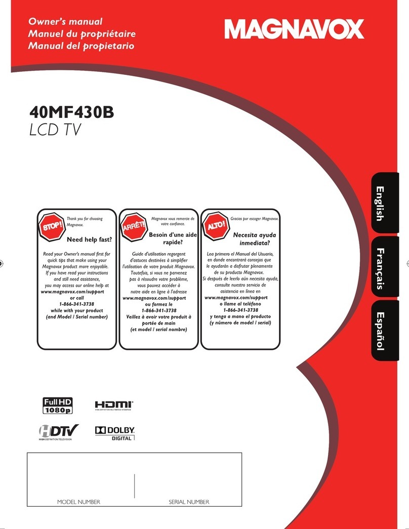
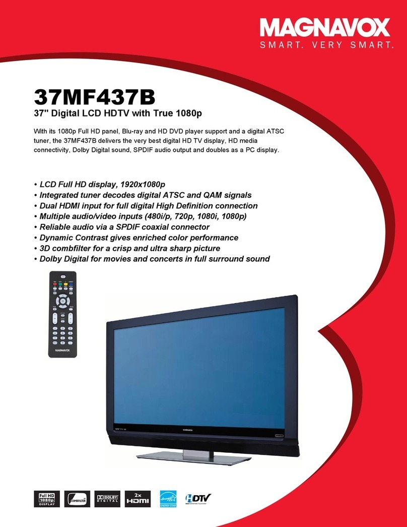
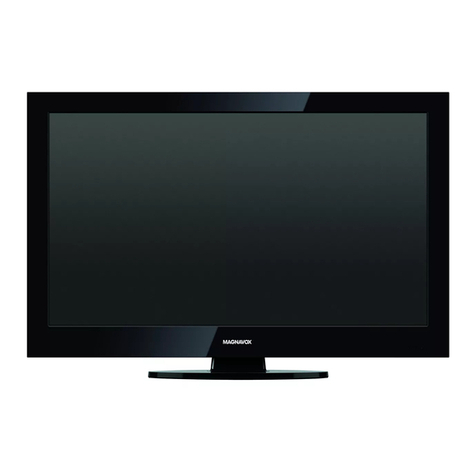
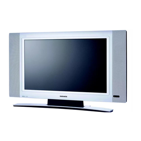
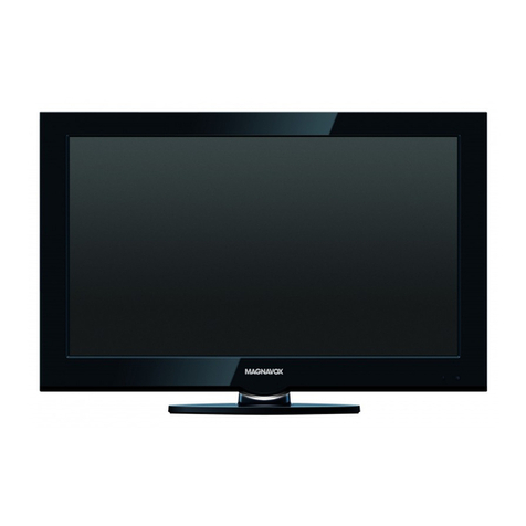
  9. Magnavox 46MF460B User manual

Magnavox 46MF460B User manual

This manual suits for next models

1

Other Magnavox LCD TV manuals

Magnavox 19ME601B User manual

Magnavox

Magnavox 19ME601B User manual

Magnavox 15MF050V/17 User manual

Magnavox

Magnavox 15MF050V/17 User manual

Magnavox 39ME412V User manual

Magnavox

Magnavox 39ME412V User manual

Magnavox 19MD358B - 19" LCD TV User manual

Magnavox

Magnavox 19MD358B - 19" LCD TV User manual

Magnavox 15MF605T - 15" Lcd Tv User manual

Magnavox

Magnavox 15MF605T - 15" Lcd Tv User manual

Magnavox 19MF338B - 19" LCD TV User manual

Magnavox

Magnavox 19MF338B - 19" LCD TV User manual

Magnavox 19MF330B - User manual

Magnavox

Magnavox 19MF330B - User manual

Magnavox 26MD255V - 26" Lcd-tv User manual

Magnavox

Magnavox 26MD255V - 26" Lcd-tv User manual

Magnavox 26MF/32MF231D User manual

Magnavox

Magnavox 26MF/32MF231D User manual

Magnavox 52MF438B/F7 User manual

Magnavox

Magnavox 52MF438B/F7 User manual

Magnavox 37MF337B - Hook Up Guide User manual

Magnavox

Magnavox 37MF337B - Hook Up Guide User manual

Magnavox 22MF339B - 22" LCD TV User manual

Magnavox

Magnavox 22MF339B - 22" LCD TV User manual

Magnavox Magnavox 32MF605W/17 User manual

Magnavox

Magnavox Magnavox 32MF605W/17 User manual

Magnavox 19MF301B User manual

Magnavox

Magnavox 19MF301B User manual

Magnavox 37MF437B - LCD TV - 1080p User manual

Magnavox

Magnavox 37MF437B - LCD TV - 1080p User manual

Magnavox 55ME345V/F7 A User manual

Magnavox

Magnavox 55ME345V/F7 A User manual

Magnavox 15MF400T/37 Series User manual

Magnavox

Magnavox 15MF400T/37 Series User manual

Magnavox 47MF437B - Hook Up Guide User manual

Magnavox

Magnavox 47MF437B - Hook Up Guide User manual

Magnavox 40ME338V User manual

Magnavox

Magnavox 40ME338V User manual

Magnavox 40MF401B/F7 User manual

Magnavox

Magnavox 40MF401B/F7 User manual

Magnavox 39ME313V User manual

Magnavox

Magnavox 39ME313V User manual

Magnavox 42MF437B - 42" Digital Lcd Hdtv User manual

Magnavox

Magnavox 42MF437B - 42" Digital Lcd Hdtv User manual

Magnavox 22ME601B User manual

Magnavox

Magnavox 22ME601B User manual

Magnavox 20MF Series User manual

Magnavox

Magnavox 20MF Series User manual

Popular LCD TV manuals by other brands

Samsung LA32E420 E-manual

Samsung

Samsung LA32E420 E-manual

ViewSonic VS12119-1M user guide

ViewSonic

ViewSonic VS12119-1M user guide

iLO CIWL3706 owner's manual

iLO

iLO CIWL3706 owner's manual

LG 32LT560C Quick reference guide

LG

LG 32LT560C Quick reference guide

Sony WEGA KLV-27HR3 operating instructions

Sony

Sony WEGA KLV-27HR3 operating instructions

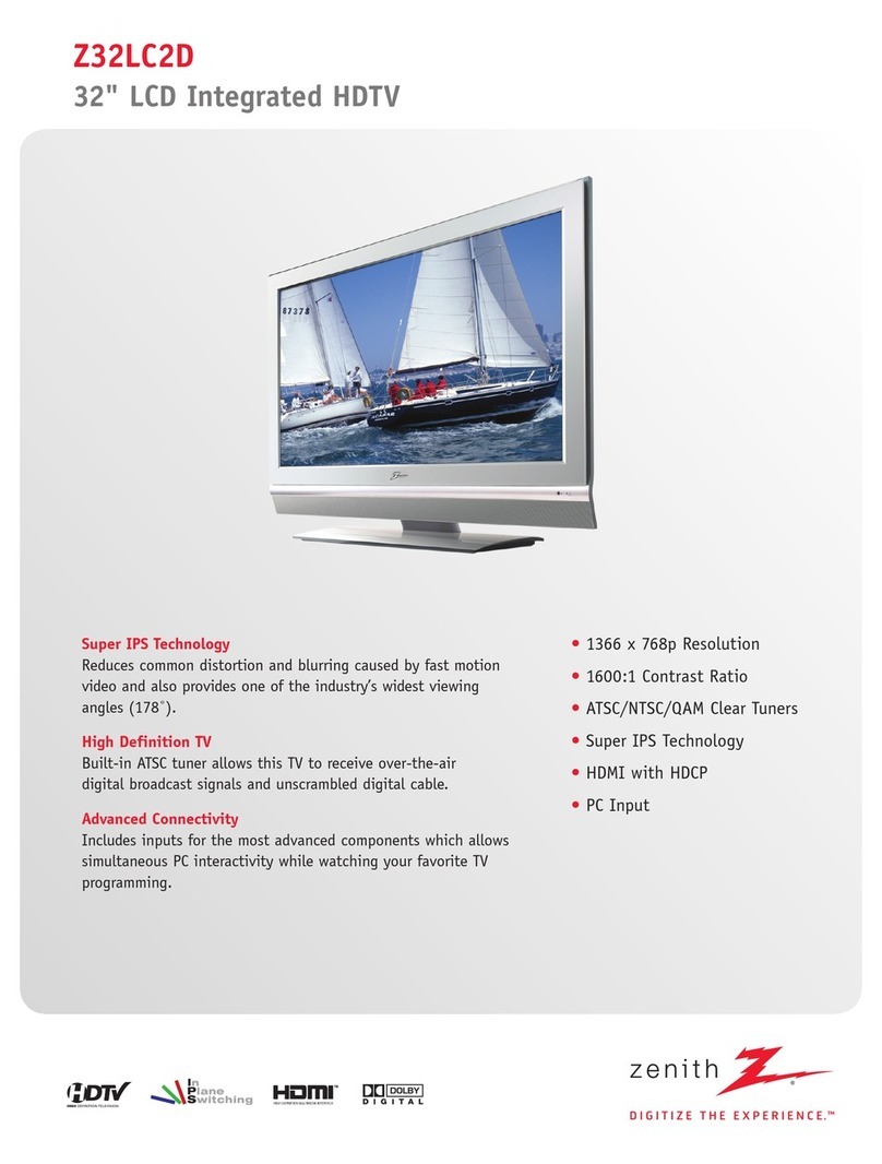
Zenith Z32LC2D Specifications

Zenith

Zenith Z32LC2D Specifications

Sony KDL-32S3000R - 32" Class Bravia S-series Digital Lcd... Specifications

Sony

Sony KDL-32S3000R - 32" Class Bravia S-series Digital Lcd... Specifications

Medion MEDION LIFE X14330 quick start guide

Medion

Medion MEDION LIFE X14330 quick start guide

Vizio HDTV30A VW32L Service manual

Vizio

Vizio HDTV30A VW32L Service manual

Sharp LC-24DV250K Operation manual

Sharp

Sharp LC-24DV250K Operation manual

SOYO Dymond DYLT032A user manual

SOYO

SOYO Dymond DYLT032A user manual

Kalley K-LED40FHDST2 Service manual

Kalley

Kalley K-LED40FHDST2 Service manual

Dynex DX-L40-10A Guide de l'utilisateur

Dynex

Dynex DX-L40-10A Guide de l'utilisateur

Hisense M3300 user manual

Hisense

Hisense M3300 user manual

Toshiba 42XV600A owner's manual

Toshiba

Toshiba 42XV600A owner's manual

Panasonic TX-26LX1A operating instructions

Panasonic

Panasonic TX-26LX1A operating instructions

HP LT3200 Illustrated parts & service map

HP

HP LT3200 Illustrated parts & service map

Sharp LC-32GA8 Service manual

Sharp

Sharp LC-32GA8 Service manual

manuals.online logo
manuals.online logoBrands
  • About & Mission
  • Contact us
  • Privacy Policy
  • Terms and Conditions

Copyright 2025 Manuals.Online. All Rights Reserved.

46MF460B
46MF440B
LCD TV
Thank you for choosing
Magnavox.
Readyour Owner'smanual first for
quick tips that make usingyour
Magnavox productmore enjoyable,
If you haveread your instructions
and still needassistance,
you may accessour onlinehelp at
www.magnavox.com Isuppart
or call
1-866-341-3738
while with your product
(and Model I Serial number)
votre confiance,
Guide d'utilisation regorgent
d'astucesdestinies a simplifier
I'utilisation de votre produit Magnavox.
Toutefois,si vousne parvenez
pas ar_soudrevotre probl_me,
vouspouvezacceder
notre aide en tigne_I'adresse
www, magnavo×.com Isupport
oa farmez le
1-866-341-3738
Veillez _ avoir vatre produit
por_e de main
(et model Iserial hombre)
Gracias par escoger Magnavo
Necesita ayuda
inmediata?
Leaprimero el Manual delUsuario,
en donde encontrar_consejosque
le ayudar_na disfrutar plenamente
de su productoMagnavox.
Si despu_sde leerlo adn necesitaayuda,
consultenuestroserviciode
asistenciaen linea en
www.mognavox.com/support
allame al tel_fono
1-866-34 I-3738
ytenga a maria el praduc_o
(y n_mero de model Iserial)
H_m| °
IT! DOLBY
DIGITAL ]
N©DEL NUM_SER SERIAL NUM_SER
Redstetin_ yourmodel with MAGNAVOX makesyoueligiblefor all ofthe valuablebenefitslistedbelow,sodon't missout,
Complete andreturnyourProduct£egistrotionCordat once,or regi_er online at www, magnavox.comlsupport toensure;
_ii!C
Cal
MAGNAVOX
Congratulations on your purchase,
and welcome to the "'family!"
Dear MAGNAVOX product owner:
Thank you for your confidence in
IAGNAVOX.You've selected one of the
best-built, best-backed products available today.
We'll do everything in our" power" to keep you happy
with your" purchase for" many years to come.
As a member of the iVlAGNAVOX"family," you're
entitled to protection by one of the most
comprehensive warranties and outstanding service
networks in the industry.What's more, your"
purchase guarantees you'll receive all the
information and special offers for which you qualify,
plus easy accessto accessories from our"convenient
home shopping network.
Host importantly, you can count on our
uncompromising commitment to your total
satisfaction.
All of this is our"way of saying welcome - and
thanks for" investingin a NAGNAVOX product.
P.S.To get the most from your MAGNAVOX
purchase, be sure to complete and return your
Product Registration Card at once or register
online at:
www.magnavox.com/support
Know these safety symbols
RISK OF ELECTRIC SHOCK
DO NOT OPEN
CAUTION : TO REDUCE THE RISK OFELECTRIC SHOCK, DO NOT
REMOVE COVER (OR BACK). NOUSER-SERVICEABLE PARTS
INSIDE. REFER SERVICING TO QUALIFIED SERVICE PERSONNEL
This "bolt of lightning" indicates
uninsulated material within your unit
may cause an electrical shock. For"the safety
of everyone in your" household, please do not
remove product covering.
The "exclamation point" calls attention to
features for" which you should read the
enclosed literature closely to prevent operating
and maintenance problems.
WARNING :To reduce the risk of fire or
electric shock, this apparatus should not be
exposed to rain or" moisture and objects filled
with liquids, such as vases,should not be
placed on this apparatus.
CAUTION :To prevent electric shock, match
wide blade of plug to wide slot, fully insert.
ATTENTION :Pour" 6viter les choc 61ectriques,
introduire la lame la plus large de la fiche dans
la borne correspondante de la prise et pousser
jusqu'au fond.
For Customer Use
Enter below the Serial No. which is located
on the rear of the cabinet. Retain this
information for" future reference.
Model No.
Serial No,
2
EN
IMPORTANT SAFETY INSTRUCTIONS
Read before operating equipment
1. Read these instructions.
2. Keep these instructions.
3. Heed aHwarnings.
4. Follow all instructions.
S. Do not use this apparatus near watel:
6. Clean only with a dry cloth.
7. Do not block any of the ventilation openings.
Install in accordance with the manufacturer's instructions.
8. Do not install near any heat sources such as radiators, heat
registers, stoves, or other apparatus (including amplifiers)
that produce heat.
9. Do not defeat the safety purpose of the polarized or
£rounding4ype plug.A polarized plug has two blades with
one wider than the othel: A grounding type plug has two
blades and third grounding prong.The wide blade or third
prong are provided for your safetxWhen the provided
plug does not fit into your outlet, consult an electrician for
replacement of the obsolete outlet.
I0. Protect the power cord fi_om being walked on or pinched
particularly at plugs, convenience receptacles, and the point
where they exit fi_om the apparatus.
11. Only use attachmentdaccessodes specified by the
manufacturei:
12. Use only with a cart, stand, tripod, bracket, or table
specified by the manufactureh or sold with the appara-
tus.When a cart is used, use caution when moving the
cart/apparatus combination to avoid injury fi_om tip-ovel:
13. Unplugthis apparatus during lightning storms orwhen un-
used for long pedods of time.
14. Refer all servicing to qualified service personnel. Servicing is
required when the apparatus has been damaged in any wa}4
such as powel_supply cord or plug is damaged, liquid has
been spilled or objects have fallen into apparatus, the appara-
tus has been exposed to rain or moisture, does not operate
normally, or has been dropped.
15. Damage Requiring Service -The appliance should be
serviced by qualified service personnel when:
A. The power supply cord or the plug has been damaged;
B. Objects have fallen, or liquid has been spilled into the
appliance;
C.The appliance has been exposed to rain
D. The appliance does not appear to operate normally or
exhibits a marked change in performance;
E. The appliance has been dropped, orthe enclosure damaged.
16. Tilt/Stability - All televisions must comply with recommended
international global safety standards for tilt
and stability properties of its cabinet design,
• Do not compromise these design standards by applying
excessive pull force to the fi_ont, or top, of the cabinet
which could ultimately overturn the product.
• Also, do not endanger yourself, or children, by placing
electronic equipment/toys on the top of the cabinet. Such
items could unsuspectingly fall fi_om the top of the set and
cause product damage and/or personal injur 4
17. Wall or Ceiling Hounting -The appliance should be
mounted to a wall or ceiling only as recommended by the
manufactu tel:
18. Power Lines -An outdoor antenna should be located
away fi_om power lines.
19. Outdoor Antenna Grounding- if an outside antenna
is connected to the receiveh be sure the antenna system is
grounded so asto provide some protection against voltage
surges and built up static charges.
Section 810 of the National Electdc Code, ANSI/NFPA
No. 70-1984, provides information with respect to proper
grounding of the mast and supporting structure, ground-
in£ of the lead-in wire to an antenna discharge unit, size of
grounding connector's, location of antenna-discharge unit,
connection to grounding electrodes, and requirements for
the grounding electrode. See Figure below.
20. Object and Liquid Entry - Care should be taken so
that objects do not fall and liquids are not spilled into the
enclosure through openings.
21. Battery Usage CAUTION -[o prevent battery
leakage that may result in bodily injury, property damage,
or damage to the unit:
• install all batteries con_ectly, with + and - aligned as
marked on the unit.
• Do not mix batteries (old and new or carbon and
alkaline, etc.).
• Remove batteries when the unit is not used for a long
time.
Note to the CATV system installer :This reminder is provided to call the CATV system installer's attention to Article
82_0-40 of the NEC that provides guidelines for proper grounding and, in particulac specifies that the cable ground shall
be connected to the grounding system of the building, as close to the point of cable entry as practicak
Example of Antenna Grounding as
)er NEC -National Electric Code aRou qDcb_ - '
_ ANTErqrqAhEALINW_kE
ANTErqNADSCHAP,GEU_'aT(r'_ECSECTIONSIO2O}
OROUrqC_IrqCCONDUCTORSrrqECSECTIONS_0 21_
C#,OU,"JOCLAMFS
ELECTr,iCSE_'_CEEQUIPMENT F'OWEkSERVICE_,ROUr'_D_NCELECTr,ODESYSTEM_NECAP,T 2S0 _ H_
3
EN
FCC WARNING
This apparatus may generate or use radio frequency energy. Changes or modifications to this apparatus may cause harmful interference
unless the modifications are expressly approved in the manual. The user could lose the authority to operate this apparatus if an
unauthorized change or modification is made.
RADIO-TV INTERFERENCE
This apparatus has been tested and found to comply with the limits for a Class B digital device, pursuant to Part 15 of the FCC Rules.
These limits are designed to provide reasonable protection against harmful interference in a residential installation. This apparatus
generates, uses, and can radiate radio frequency energy and, if not installed and used in accordance with the instructions, may cause
harmful interference to radio communications. However, there is no guarantee that interference will not occur in a particular installation.
If this apparatus does cause harmful interference to radio or television reception, which can be determined by turning the apparatus off
and on, the user is encouraged to try to correct the interference by one or more of the following measures:
1) Reorient or relocate the receiving antenna.
2) Increase the separation between the apparatus and receiver.
3) Connect the apparatus into an outlet on a circuit different from that to which the receiver is connected.
4) Consult the dealer or an experienced radio/TV technician for help.
DECLARATION OF CONFORMITY
Trade Name: NAGNAVOX Responsible Party: FUNAI CORPORATION, Inc.
Model: 46NF460B/46NF440B Address: 19900 Van Ness Avenue, Torrance, CA 90501 U.S.A.
Telephone Number: I-866-341-3738
This ClassB digital apparatus complies with Canadian ICES-003. Standard TelevisionReceivingApparatus, Canada BETS-7/NTM R-7
CAUTION: Danger of explosion if battery is incorrectly replaced. Replace only with the same or equivalent type.
WARNING :Batteries (battery pack or battery installed) shallnot be exposed to excessive heat such as sunshine,fire or the like.
Disconnect the mains plug to shut off when find trouble or not in use.The mains plug shall remain readily operable.
This apparatus should not be placed in a built-in installation such as a bookcase or rack unless proper ventilation is provided.
Make sure to leave a space of 4 inches (10cm) or more around this apparatus.
WARNING: To prevent injury, this apparatus must be securely attached to the wall in accordance with the instructions.
_il<eall LCD products, this set contains alamp with Mercury, please dispose of according to all Local, State and
Federal laws. For the disposal or recycling information, contact:
/www.mygreenelectronics.com or www.eiae.org
Do not place the unit on the furniture that is capable of being tilted by a child and an adult leaning, pulling, standing or
climbing on it. A falling unit can cause serious injury or even death.
4
EN
NOTE ABOUT RECYCLING
• [his unit's packaging materials are recyclable and
can be reused, Please dispose of any materials in
accordance with your local recycling regulations,
• Batteries should never be thrown away or
incinerated but disposed of in accordance with your
local regulations concerning chemical wastes,
WHEN CARRYINGTHIS UNIT
• At least2_people are required when
• caTyingthis unit.
Make sureto hold the upper and bottom (
fi_amesof the unit firmly as illustrated.
TO AVOID THE HAZARDS OF
ELECTRICAL SHOCK AND FIRE
• Do not handle the AC power cord with wet hands.
• Do not pull on the AC power cord when disconnecting it fi_om an
AC outlet. Grasp it by the plug.
• Do not put your fingers or objects into the unit.
Trademark Information
•HDMI,the HDMI Logo, and High-Definition Multimedia Interface
are trademarks or registered trademarks of HDMI Licensing LLC
in the United States and other countries,
IT! DOLBY
DIGITAL I
Manufactured under license fi_om Dolby Laboratories. Dolby and
the double-D symbol are trademarks of Dolby Laboratories.
The American Academy of Pediatrics discourages television
viewing for children younger than two years of age.
LOCATION AND HANDLING
• Do not install the unit in direct sunlight or in a place subject to
dust or strong vibration,
• Avoid a place with drastic temperature changes.
• Install the unit in a horizontal and stable position. Do not place
anything directly on top or bottom of the unit. Depending on
your external devices, noise or disturbance of the picture and/or
sound may be generated if the unit is placed too close to them.
In this case, please ensure enough space between the external
devices and the unit.
Depending on the environment, the temperature of this unit may
increase slightl}4This is not a malfunction.
Be sure to unplug the AC power cold fi_om the AC outlet before
caiTying the unit.
INTRODUCTION
Contents
Important Safety Instructions
Ti_ademark In.formation
INTRODUCTION
Features
Supplied Accessories
Symbols Used in this Manual
Attaching the Base
Fixing the Unit onYour Furniture
Control Panel
Terminals
Remote Control Function
Installing the Batteries
PREPARATION
Antenna Connection
Connection to Cable Receiver or Satellite Box
External Device Connection
Cable Management
Plug In the AC Power Cold
Initial Setup
WATCHING TV
SieepTimer
Switching Each Input Node
Freeze Mode
Channel Selection
TV Screen Dispby Node
Sound Functions
TV Screen Information
Reducing the Brightness
Fun-Link ©ptions
OPTIONAL SETTING
Main Menu
Autoprogram
Channel List
Add Channels
Antenna Confirmation
Language Selection
Picture Adjustment
Sound Adjustment
Closed Caption
Child Loci<
Fun-Link
Energy Saving Mode
Location
120Hz Clear PJ×Engine Demonstration Mode
Current Software Info
HP3/jPEG Playback
TROUBLESHOOTING
Ti_oubleshootin£ Guide
FAQ
INFORMATION
Glossary
Maintenance
General Specifications
Electrical Specification
Other Specifications
Limited Warranty
3
4
s
6
6
6
6
7
7
8
8
9
9
I0
14
14
15
16
16
16
16
17
17
18
18
18
19
19
20
20
21
21
22
22
24
27
29
30
3O
30
3O
31
Featu res
DTV/TV /CATV
You can use your remote control to select channels which
are broadcast in digital format and conventional analog
format Also, cable subscribers can access their cable T_!
channels.
Information Display (ATSC only)
You can display the title, contents and other information of
the current DT_! program on theT_! screen.
Autoprogram
This unit automatically scans and memorizes channels
available in your area, eliminating difficult setup procedures.
Child Loci(
This feature allows you to block children's access to
inappropriate programs
Closed Caption Decoder
Built-in closed caption decoder displays text for closed
caption supported programs.
MTS/SAP Tuner
Audio can be selected fi_om the remote control. .....
Z
Auto Shut Off Function ::,
If there is no input signal and no operation for 15 minutes,
the unit will turn off automatJcallx
Sleep Timer
This feature will automatically turn offthe power of the unit at !ili_
a specific time.
Choices for On-screen Language
Select your on-screen language:
English, Spanish or French. ?i:{
Stereo Sound Function
PLL Frequency Synthesized Tuning
Provides fi_ee and easy channel selection and lets you tune
directly to any channel using the number and decimal point ":::i ..............
%" buttons on the remote control. 1}
Various Adjustment for Picture and Sound :::
Customizes image quality suitable for your room and sets
your sound preference. :z
Fun-Link via HDMI Link }'_
(HDMI Cable not Included)
Fun-Link allows your" other HDHI link devices (such as
Magnavox DVD) to be controlled by the HDMI cable ............................
connected to yourTM
120Hz Clear Pix Engine _i:'!
[his feature activates a 120Hz Clear Pix Engine drive
using 120 fi_ames per second resolution to enhance the m
smoothness of fast moving pictures and reduce blur in the
pictu re. ()
HDMt Input Z
When using HDMII Input, you can enjoy this unit as a PC ..................................
monitor if your PC has a DVI output terminal.
ComponentVideo Input
S-Video Input
AV Input
USB Terminal
The MP3 music and the jPEG picture files stored on a USB
flash memory device can be played back on this unit.
Digital Audio Output
Analog Audio Output
32
34
35
35
36
36
36
37
© 2010 Funai Electr c Co,, Ltd.
All Iights reserved, No part of this manual may be reproduced, copied,
transm tted, d sseminated, transcribed, down oaded or stored in any storage
reed urn, n any form or for ny purpose wthout the express pror wrtten
consent of Funai,Furthermore, any unauthor zed commerc al d stribution of this
manual or any rev sion hereto s stricty prohibited,
Infurmadon n this document s subject to change without notice, Funai
reserves the right to chnge the content herein without the obligation to
hotly any person or or%n zadon of such changes,
F'UN_ with the _'_ design s registered trddemark of Funa Eectric Co.,
Ltd. and may not be used n any way without the express written consent
of Funai, AI} other trademarks used herein remain the excusve property
of ther respective owners. Nothing cont ined in this manual shoud be
construed as grar,tin£, by mpication or otherwse, any icense or rght to
use any of the tr demarks disp ayed herein, Misuse of any tr demarks or
any other content n this manul s str ctly proh bited, Funai shall aggressively
enforce ts inte lectua property rghts to the fu lest extent of the law,
5
EN
Supplied Accessories
Owner's manual Quick Start
(1EPIN26819) (1EPIN25860)
Remote control Registration card
(NFd04UD) (1EHN25026)
AC power cord
(WAV0t 62LW001) or
(WAV0162LTE03) or
(WAV152ZH N00t )
Batteries Screw kit
(AAA, 1.SV x 2) for attaching the base
(1ESA2436S)
If you need to replace these accessories, please refer
to the part No. with the illustrations and call our toil
free customer support line found on the cover of this
manual.
Note
• If you lose the screws, please purchase HSx12 Phillips head screws at your
local store,
Attaching the Base
You must attach the base to the unit to have it as a table top
unit. Be sure the front and rear of the base match the proper
direction.
2
3
Spread a thick and soft
cloth over a table as
shown.
Place the main unit face
up onto it. Make sure not
to damage the screen, At
least 2_people are required
for this step,
Insert 2_hooks under the
bottom of the main unit
into base holes, (shown by
arrow (_)),then move the
base in the direction as
shown by arrow @ until it
stops and the 6 mounting
holes are aligned.
Drive Phillips head screws
into the 6 threaded holes
at the bottom of the base
until they are tight.
To remove the base from ths unt
• Unscrew the Phillips head screws on step 3.
After the screws are removed, move tlne base in the opposite direction as
slnown by arrow (2) on step 2, then pull tlne base up toward the front of the
unit. Be careful not to drop the base when you remove it.
Note
• When attaclning the base, ensure that all screws are tightly fastened. Iftlne
base is not properly attached, it could cause the unit to fall, resulting in
injuries as well as damage to the unit.
• Make sure to use a table which can support the weight of this unit and is
larger tlqan tNs unit.
• Make sure tlne table is in a stable location,
• When attaching the base, ensure that FRONT t written on the base is
upward, if it's not upward, the 2 hooks don't fit in the base,
Symbols Used in this Manual
The following isthe description for the symbols used in
this manual. Description refers to:
:DigitalTV operation
:Analog/Cable TV operation
• If neither symbol appears, the operation is applicabie to
both.
Fixing the Unit on Your Furniture
Screw this unit on your furniture tightly using wood screws
(not supplied) in the 2 holes atthe bad< of the base as shown.
• Recommended screw dimension :5,1 × 20 mm
rear of this unit
holes
Note
• Wlqen you remove this unit make sure to unscrew the wood screws fi_om
yourWood Stand, Furn ture and other wood tenn.
6
EN
Control Panel
5
6
7
Terminals
11
12
13
14
15
16
17
18
19
20
Note tlor USB termina_
•User should not connect any devices to the USB terminal such as digital
camera, keyboard, mouse, etc, (because these will not work).
• The software update is, in most cases, handled by an authorized service
person or in some circumstances the user may be asked to do the software
upda±e themselves,
1 VOLUME +/- ,l,,_p.17
Press to adjust the volume or
move right (+)/left (-) through the main menu items.
2 MENU O ii,i_ p.19
3 CHANNEL +/- ii,i_ p.16
Press to setect channets or
move up (+)/down (-) through the main menu items,
4 POWER _ ii,_ p.15
5 Infrared sensor window
Receives infrared rays transmitted from the remote
control,
6POWER indicator
Lights up green when power is on,
7 STAND BY indicator
Lights up red when power is off,
Side Panel
8 HDMI 3 Input jack _,_ p.9, 10
9 USB terminal _,_ p.14
Use this terminal only to playbackthe ivip3 musicand
the JPEGpicture files stored on a USBflashmemory
device,or when software update isneeded.
10 S-Video /Composite Video/Audio (L/R)
Input jacks forVlDEO2 _,i_ p.11, 12
Rear Panel
11
12
13
14
15
16
17
18
19
2O
Cable management IlllI_ p.14
AC power Inlet IlllI_ p.14
HDMI 2 Input jack i_,i_p.9, 10
HDMI 1 Input jack i_,i_p.9, 10, 13
HDPII connection for HDPII or DVI device.
When you connect your PCthat hasa DVI terminal,
you canenjoy this unit asa PC monitor.
Antenna Input jack i_li_ p.9
S-Video /Composite Video/Audio (L/R)
Input jacks forVlDEO1 i_,i_p.11, 12
ComponentVideo and Audio (L/R) Input jacks
IIIlI_ p.9, 11
Digital Audio Output jack i_,i_p.12
Audio (L/R) Output jacks ii,i_ p.12
Audio (L/R) Input jacks for HDMI 1
ii,i, p.10, 13
Audio cable connection from a DVIdevice.
When you connect your PCthat hasa DVI terminal,
usea stereo mini plug conversion cable aswelt.
(For HDMI 1 Input jack only)
z
(;]
0
7_
C]
Z_
o
z
O
z
7
EN
8
EN
Remote Control Function
1
2
3
4
5
10
11
12
13
14
15
16
17
18
19
2O
When using a universa_ remote control to operate ths unt_
• Make sure the component code on your universal remote control is set
to our brand. Refer to the manual accompanying your remote control for
more details.
• We do not guarantee 100% interoperability with all universal remote
controls.
Note
• Buttons in gray background ( ) are not available unless you are
connected to devices that are compatible with Fun-Link function,
• We do not guarantee 100% interoperability with other- brands of blDHI link
compliant devices,
Batter')/Precsut ons:
• Be sure to follow the correct polarity as indicated in the battery
compartment Reversed batteries may cause damage to the device.
• Do not mix diff_r-ent types of batteries together- (e,g.AIkaline and
CarbomZhTc, or rechargeable batteries like ni-cad, ni-mh, etc) or- old
batteries with fresh ones.
• If the device is not to be used for a long period of time, remove the
batteries to prevent damage or injury from possible battery leakage.
• Do not try to recharge batteries; they can overhea± and rupture,
1(j) (power) ,,,,Jp.lS
2 SAP HllI_p.17
3 SOURCE HllI_p.16
4 FREEZE HllI_p.16
Press to freeze screen image.
5 OK IlllI_p.lS
6 A/T/_I/I_ (cursor) IlllI_p.15
7 BACK _ IlllI_p.18
Press to return to the previous menu operation.
8 VOL +/- illli_p.17
9 PREV CH illli_p.16
Press to return to previously viewed channel.
10 SLEEP illli_p.16
11 FORMAT illli_p.17
Press to select aspect ratio available for theTV screen.
Functionally useful for Fun-Link.
13 MENU II_p.19
14 INFO ,I_ p.18
t5 REV ,_I/FWD __,.p.29
Press to searcn oacKward or forwana tnrougn the disc.
PLAY I_ I,.p.29
Press to begin the disc playbacK.
SKIP I_I_I/SKIP _ i_J. p.29
Press to SKiDbackward or forward chapters, titles or
16
17
18
19
tracks of the disc.
PAUSE II _,. p.29
Press to Dause the d_scDIavDacK.
STOP • IJ. p.29
Press to stoD the disc Dla DaCK.
MUTE ,J p.17
CH +/- ,J p.16
ECO llI_p.18
Press to reduce the brightness.
Number buttons IlI_ p.16
•(dot)
Press to shift the subchannet from the main channel,
20 FUN-LINK OPTIONS _ IIllI_p.18, 29
Press to call up various menu from your Fun-linl< device
connected through an HDHI cable.
Installing the Batteries
Install the batteries (AAA, 1.5V x 2) matching the polarity
indicated inside battery compartment of the remote control.
PREPARATION
Before you connect:
Be sure your antenna or other device is connected properly
before plugging in the AC power cord.
Connection to Cable Receiver or
Satellite Box
Use an HDHI or component video cables to connect the
HDPII or the ComponentVideo Input jacks of the unit to
the HDPII or the component video output jacks of the cable
receiver/satellite box.
If you connect to the unit's ComponentVideo Input jacks,
connect audio cables to the Audio L/R Input jacks right beside
the ComponentVideo connector
e.g.) satellitedish
_J
Antenna Connection
Connect the RF coaxial cable on your home outlet to the
antenna input jack of this unit.
e.g.)
VHF/UHF
analogII'
or
DTV antenna e
e
RF coaxial cable
cable TV signal
RF coaxial cable
cable TV signal cable receiver/
including PPV satellite box A
rear of this unit
Once connections are completed,turn on the unit and begin initial
setup. Channel scanning is necessary for the unit to memorize all
available channels in your area. [Initial Setup] ,,,_p.15
Note
if you have any question about the DTV's antenna, visit www.antennaweb,
org for further information.
Depending on your- antenna system, you may need different types of
combiners (mixers) or separators (splitters). Contact your local electronics
store for these items.
For your- safety and to avoid damage to this unit, please unplug the RF
coaxial cable fi-om the antenna input jack before moving the unit,
if you did use an antenna to receive analogTV, it should also work for DTV
reception. Outdoor or attic antennas will be more effective than a set top
or- inside antenna,
To switch your reception source easily between antenna and cable, install an
anterlna selectoE
if you are not receiving a signal fl_om your cable service, contact the Cable
provide_:
side or rear of
this unit
You can also connect this unit to the cable receiver or satellite box
other than the HDHI or the component video output jacks because
they might have different output jacks.
Required cables and connecting methods of the cable receiver/
satellite box, or the availability channel for the clear QAN may differ
depending on the cable/satellite providel: For more in:formation,
please contact your cable/satellite providel:
O
z
9
EN
External Device Connection
HDMI Connection
HDiVil connection offers the highest picture quality.
mDiVil (High Definition Multimedia Interface) transports high definition
video and multi-channel digital audio through a single cable,
e.g.)
BD/DVD recorder
with the HDMI output jack
HDMI-DVI Connection
Use an HDiViI-DVI conversion cable to connect the unit to
external video devices equipped with DVI output jack,
e.g.)
side or rear of this unit
rear of this unit
audio cables
Note
For HDMI connection
The unit accepts 480i, 480p, 720p, 1080i and 1080p 24/30/601 Iz of video
signals, and 32kHz, 44.1 kHz and 48kHz of audio signals.
This unit accepts only 2 channel audio signal (LPCN).
You need to select "PCN" for the digital audio of the device you connected
or check the HDMI audio setting.There may be no audio output if you
select "Bitstream', etc,
This unit accepts only signals in complialTce with EIA861.
or HDMI-DVI connection
• The unit accepts 480i, 480p, 720p, 1080i and 1080p video signals.
• HDINPDVI connection requires separate audio connections as well and the
audio signals are converted from digital to analog.
• DVi does not display 480i image which is not in comp%nce with EIA/
CEA 861/861B.
10
EN