1Monomag 180
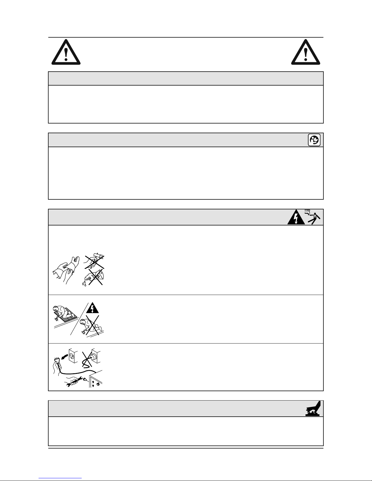
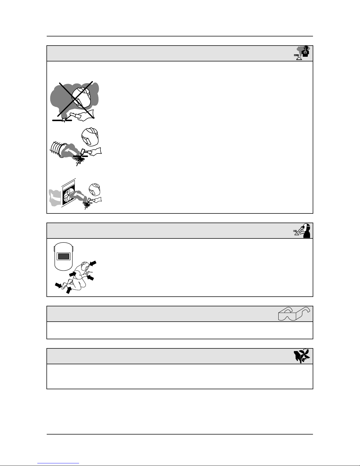
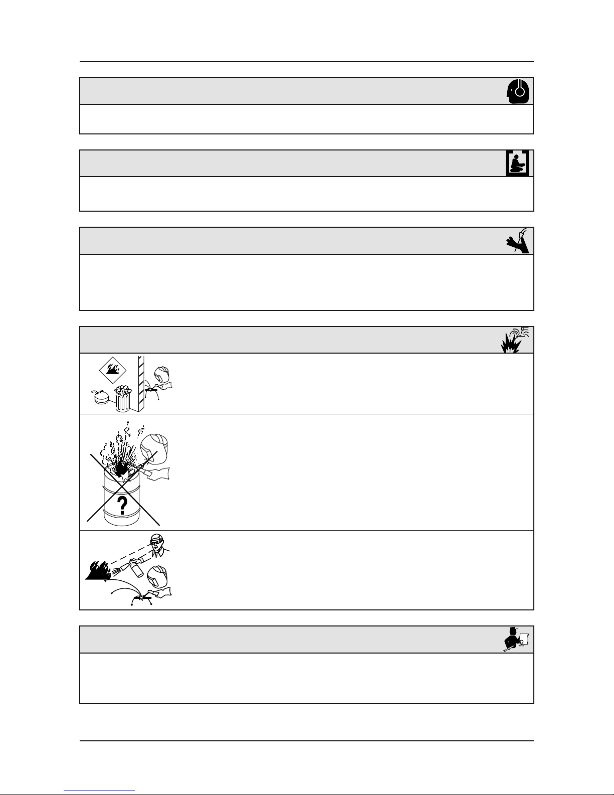
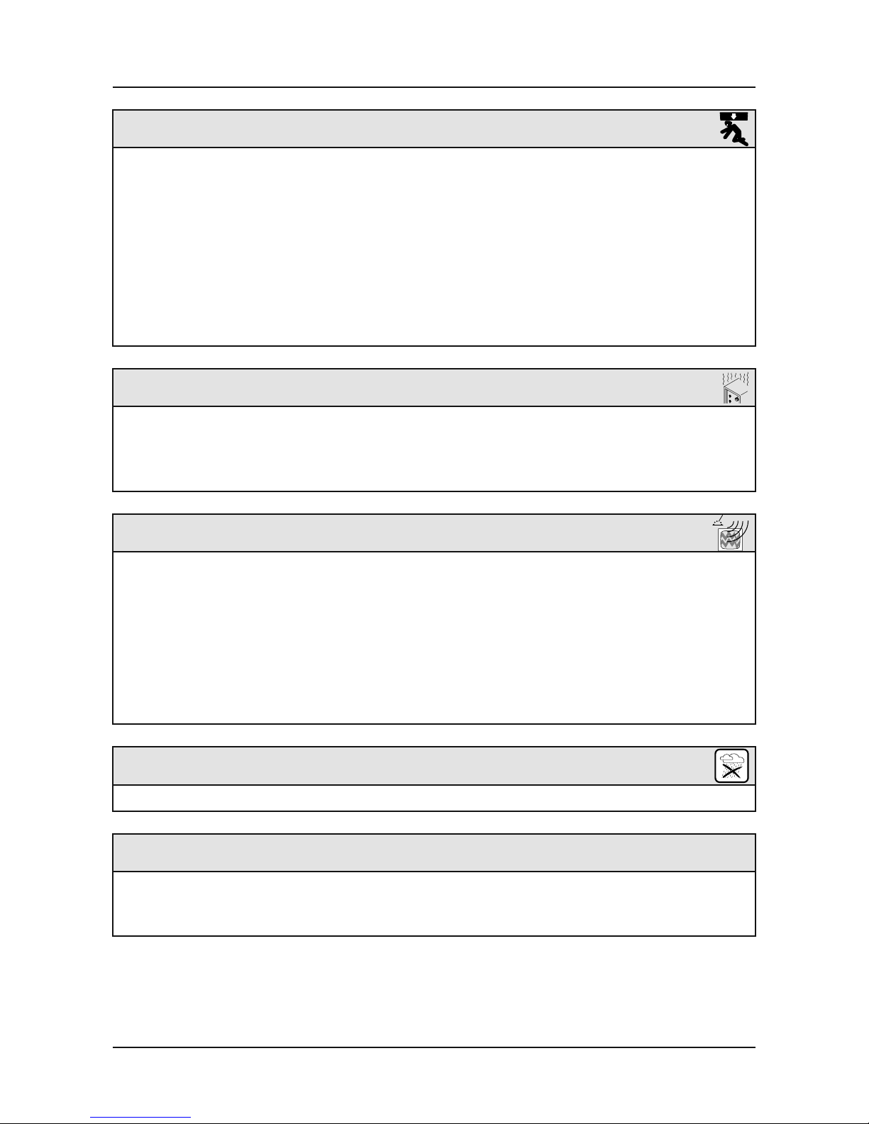
SAFETY RULES
1. TECHNICAL INFORMATIONS
1.1 GENERAL EXPLANATIONS
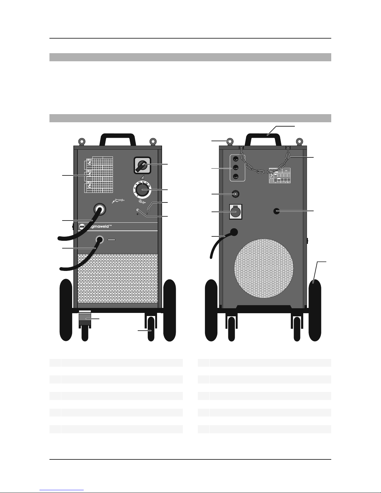
1.2 COMPONENTS OF MONOMAG 180
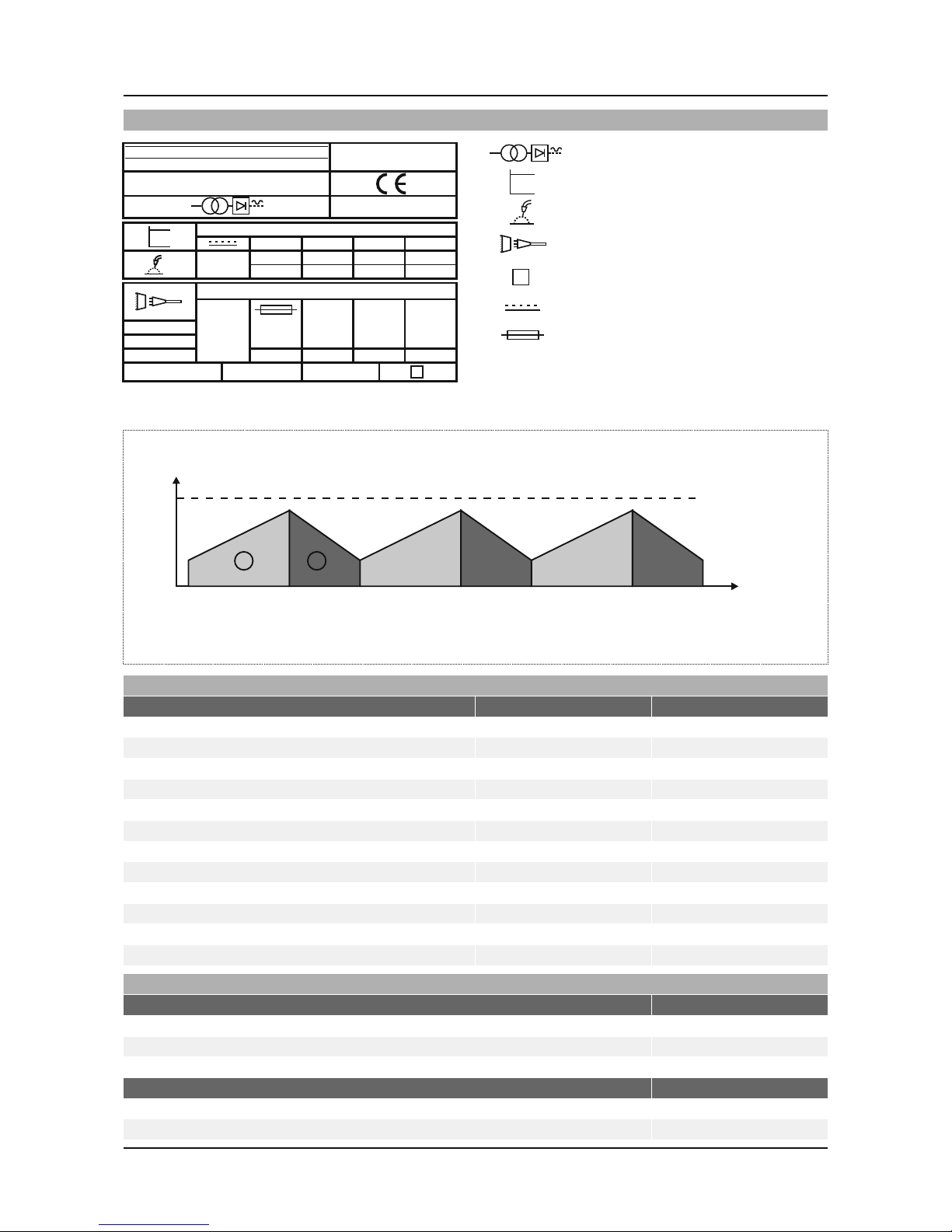
1.3 DATA PLATE
1.4 TECHNICAL SPECIFICATIONS
1.5 ACCESSORIES
2. INSTALLATION
2.1 UPON RECEIPT AND CLAIMS
2.2 INSTALLING AND WORKING RECCOMENDATIONS
2.3 WELDING CONNECTIONS
2.3.1 Earth Clamp Connection
2.3.2 Connections
3. OPERATION
3.1 CONNECTING TO THE MAINS
3.2 CHOOSING AND CHANGING THE WIRE FEEDING ROLLS
3.3 LOADING THE WIRE SPOOL AND THREADING THE WIRE
3.4 ADJUSTING THE GAS FLOW
4. WELDING
4.1 ADJUSTING THE STICK OUT
4.2 WELDING PARAMETERS
5. MAINTENANCE AND TROUBLESHOOTING
5.1 PERIODIC MAINTENANCE
5.2 NONPERIODIC MAINTENANCE
5.3 BASIC TROUBLESHOOTING
5.4 FUSES
APPENDIX 1: SPARE PARTS LIST
APPENDIX 2: ELECTRICAL DIAGRAM
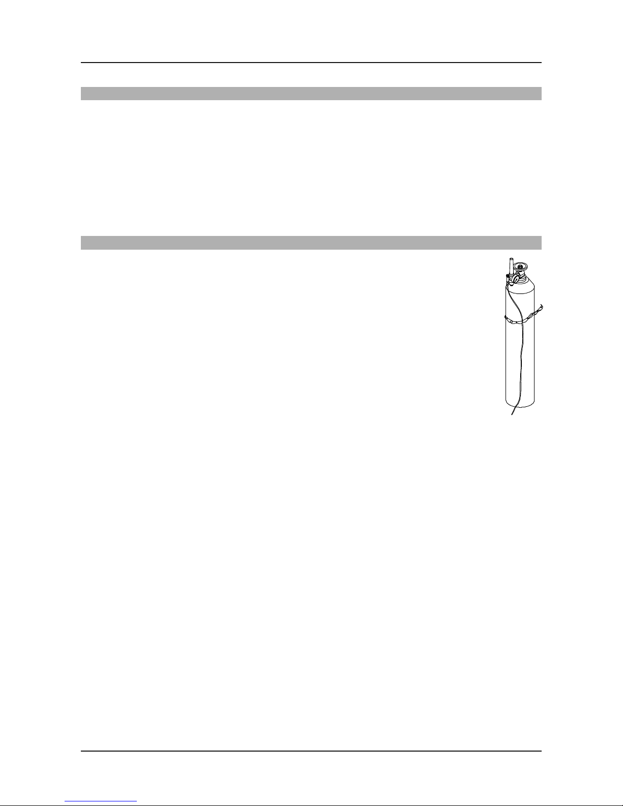
Gas
.................................................................................................................................................2
...............
..............................................................................................................7
........................................................................................................................................7
..............................................................................................................................................8
................................................................................................................8
............................................................................8
.....................................................................................................................9
.................................................................................................................9
.............................................................................................................................9
................................................................................................................................................10
10
...............................................................10
................................................................................................................11
......................................................12
............................................................................................12
........................................................................................................6
....................................................................................................................6
......................................................................................................6
............................................................................................................................................7
.............................................................................................................
..............................................................10
.....................................................................................................................................................12
.........................................................
.........................
..............................................................................................13
...................................................................................................................13
...........................................................................................................13
...............................................................................................................14
...................................................................................................................................................14
................................................................................................................15
.........................................................................................................16
CONTENTS