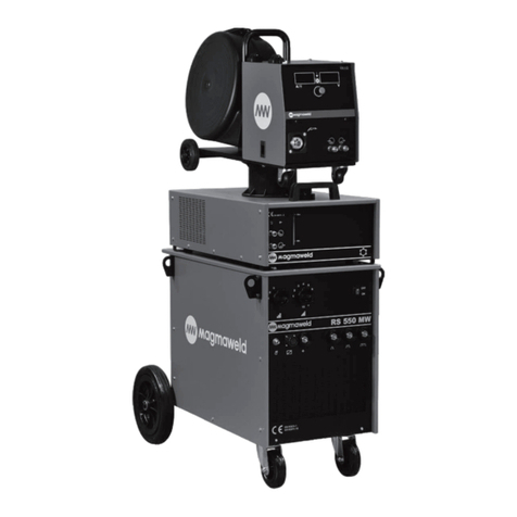
MAGNAWELD RD 650 MW User manual

USER MANUAL
KULLANIM KILAVUZU
RD 650 MW
MIG / MAGWELDING MACHINE
(+90) 444 93 53
magmaweld.com
info@magmaweld.com (+90) 538 927 12 62
MIG / MAG KAYNAK MAKİNESİ
EN
TR

Müşteri Hizmetleri: 444 93 53
E-posta: info@magmaweld.com
Organize Sanayi Bölgesi, 5. Kısım 45030 Manisa / TÜRKİYE
Tüm haklarısaklıdır.MagmaMekatronik Makine Sanayi veTicaret.A.Ş.’ninyazılıizni olmaksızın bu dökümanın tamamınınyada bir bölümünün kopyalanmasıyasaktır.
Magma Mekatronik önceden haber vermeksizin bilgilerde ve resimlerde değişiklik yapılabilir.

EN
www.magmaweld.com
RD 650 MW 3
USER MANUAL | KULLANIM KILAVUZU
CONTENTS
1
1.1
1.2
1.3
1.4
1.5
2
2.1
2.2
2.3
2.4
2.4.1
2.4.2
3
3.1
3.2
3.3
3.4
3.5
3.6
3.7
3.8
3.9
4
4.1
4.2
4.3
4.4
5
6
7
8
9
SAFETY PRECAUTIONS
TECHNICAL INFORMATION
General Information
Machine Components
Product Label
Technical Data
Accessories
INSTALLATION INFORMATION
Delivery Control
Installation And Operation Recommendations
Mains Plug Connection
Welding Connections
Connecting the Earth Cable to the Workpiece
Gas Connection
USAGE OPERATION
User Interface
MIG Cycle
Menu Structure
Connecting To The Mains
Choosing And Changing TheWire Feeding Rolls
Loading The Wire Spool And Hreading The Wire
Adjusting The Gas Flow
Starting The Welding And Finishing The Welding
Welding Parameters
MAINTENANCE AND FAILURE INFORMATION
Maintenance
Non-Periodic Maintenance
Troubleshooting
Error Codes
ANNEX 1 SPARE PARTS LIST
ANNEX 2 SPARE PARTS LIST (WIRE SLIDING UNIT)
ANNEX 3 SPARE PARTS LIST (POWER SOURCE)
ANNEX 4 SPARE PARTS LIST (WATER COOLING UNIT)
ANNEX 5 ELECTRICAL DIAGRAM
4
10
10
10
11
12
12
13
13
13
14
14
14
14
15
15
16
16
17
17
18
19
20
20
21
21
21
22
23
24
25
26
27
28
Contents
TR

RD 650 MW
EN
www.magmaweld.com
4
USER MANUAL | KULLANIM KILAVUZU
Safety Precautions
SAFETY PRECAUTIONS
Be Sure To Follow All Safety Rules In This Manual!
Make certain that the installation procedures comply with national electrical standards and
other relevant regulations, and ensure that the machine is installed by authorized persons.
• Safety symbols found n the manual are used to dentfy potental hazards.
• When any one of the safety symbols are seen n ths manual, t must be understood that there s a rsk
of njury and the followng nstructons should be read carefully to avod potental hazards.
• The possessor of the machne s responsble for preventng unauthorzed persons from accessng the
equpment.
• Persons usng the machne must be experenced or fully traned n weldng; they have to read the
user manual before operaton and follow the safety nstructons.
• Read the user manual, the label on the machne and the safety nstructons carefully.
• Make sure that the warnng labels on the machne are n good condton. Replace mssng and
damaged labels.
• Learn how to operate the machne, how to make the checks n a correct manner.
• Use your machne n sutable workng envronments.
• Improper changes made n your machne wll negatvely aect the safe operaton and ts longevty.
• The manufacturer s not responsble for the consequences resultng from the operaton of the devce
beyond the specfed condtons.
• Wear dry and sturdy nsulated gloves and workng apron. Never use wet or damaged gloves and wor
kng aprons.
• Do not touch the electrode wth the bare hand.
• Never touch parts that carry electrcty.
• Never touch the electrode f you are n contact wth the electrode attached to the work surface, oor
or another machne.
• By solatng yourself from the work surface and the oor, you can protect yourself from possble
electrc shocks. Use a non-ammable, electrcally nsulatng, dry and undamaged nsulaton materal
that s large enough to cut o the operator’s contact wth the work surface.
• Do not connect more than one electrode to the electrode holder. Keep the machne turned o when
not n use.
• Before reparng the machne, remove all power connectons and/or connector plugs or turn o the
machne.
• Be careful when usng a long mans cable.
• Check all cables frequently for possble damage. If a damaged or an unnsulated cable s detected,
repar or replace t mmedately.
• Make sure that the groundng of the power lne s properly connected.
ATTENTION
Indcates a potentally hazardous stuaton that could cause njury or damage. In case f no precauton s
taken, t may cause njures or materal losses / damages.
IMPORTANT
Specfes notfcatons and alerts on how to operate the machne.
DANGER
Indcates a serous danger. In case f not avoded, severe or fatal njures may occur.
Explanation Of Safety
Information
Comprehending Safety
Precautions
Electric Shocks
May Kill
Definition Of Safety
Symbols

EN
www.magmaweld.com
RD 650 MW 5
USER MANUAL | KULLANIM KILAVUZU
Safety Precautions
Long-term inhalation of smokes and gases released from welding and cutting is very
dangerous.
• Keep away from the movng parts.
• Keep all protectve devces such as covers, panels, aps, etc., of machnery and equpment closed and
n locked poston.
• Wear metal toe shoes aganst the possblty of heavy objects fallng on to your feet.
• Use a sutable protectve mask and glass flter (4 to 13 accordng to EN 379) sutable for that to
protect your eyes and face.
• Protect other naked parts of your body (arms, neck, ears, etc.) wth sutable protectve clothng from
these rays.
• Enclose your work area wth ame-resstant foldng screens and hang warnng sgns at eye level so
that people around you wll not sustan njures from arc rays and hot metals.
• Ths machne s not used for heatng of cebound ppes.Ths operaton performed wth the weldng
machne causes exploson, fre or damage to your nstallaton.
• Burnng sensatons and rrtatons n the eyes, nose and throat are sgns of nadequate ventlaton. In
such a case, mmedately boost the ventlaton of the work area, and f the problem perssts, stop the
weldng process completely.
• Create a natural or artfcal ventlaton system n the work area.
• Use a sutable smoke extracton system where weldng and cuttng works are beng carred out. If
necessary, nstall a system that can expel fumes and gases accumulated n the entre workshop. Use a
sutable fltraton system to avod pollutng the envronment durng dscharge.
• If you are workng n narrow and confned spaces or f you are weldng lead, beryllum, cadmum,
znc, coated or panted materals, use masks that provde fresh ar n addton to the above precaut
ons.
• If the gas tanks are grouped n a separate zone, ensure that they are well ventlated, keep the man
valves closed when gas cylnders are not n use, pay attenton to possble gas leaks.
• Sheldng gases such as argon are denser than ar and can be nhaled nstead of ar f used n confned
spaces.Ths s dangerous for your health as well.
• Do not perform weldng operatons n the presence of chlornated hydrocarbon vapors released
durng lubrcaton or pantng operatons.
Moving Parts May
Cause Injuries
Arc Light May
Damage Your Eyes
And Skin
Smoke And Gases
May Be Harmful To
Your Health
• Performng works such as weldng, surface grndng, and brushng cause sparks and metal partcles
to splatter. Wear approved protectve work goggles whch have edge guards under the weldng masks
to prevent sustanng possble njures
Sparks And Spattering Particles
May Get Into Eyes And
Cause Damage
Hot Parts May Cause
Severe Burns
Noise May Cause
Damage To Your
Hearing Ability
• Do not touch the hot parts wth bare hands.
• Wat untl the tme requred for the machne to cool down before workng on ts parts.
• If you need to hold hot parts, use sutable tools, weldng gloves wth hgh-level thermal nsulaton
and fre-resstant clothes.
• The nose generated by some equpment and operatons may damage your hearng ablty.
• Wear approved personal ear protectve equpment f the nose level s hgh.

RD 650 MW
EN
www.magmaweld.com
6
USER MANUAL | KULLANIM KILAVUZU
• Do not pont the torch towards any part of the body, other persons, or any metal whle unwrap png
the weldng wre.
• When weldng wre s run manually from the roller especally n thn dameters the wre can slp out
of your hand, lke a sprng or can cause damage to you or other people around, therefore you must
protect your eyes and face whle workng on ths.
• In small-szed and confned spaces, absolutely make sure to perform weldng and cuttng operatons,
accompaned by another person.
• Avod performng weldng and cuttng operatons n such enclosed areas as much as possble.
• Take all necessary precautons when movng the machne.The areas where the machne to be
transported, parts to be used n transportaton and the physcal condtons and health of the person
carryng out the transportaton works should be sutable for the transportaton process.
• Some machnes are extremely heavy; therefore, make sure that the necessary envronmental safety
measures are taken when changng ther places.
• If the weldng machne s to be used on a platform, t must be checked that ths platform has sutable
load bearng lmts.
• If t s to be transported by means of a haulage vehcle (transport trolley, forklft etc.), make sure of
the durableness of the vehcle, and the connecton ponts (carryng suspenders, straps, bolts, nuts,
wheels, etc.) that connect the machne to ths vehcle.
• If the machne wll be carred manually, make sure the durableness of the machne apparatuses
(carryng suspenders, straps, etc.) and connectons.
• Observe the Internatonal Labor Organzaton’s rules on carrage weghts and the transport regulat-
ons n force n your country n order to ensure the necessary transport condtons.
• Electrcal equpment should not be repared by unauthorzed persons. Errors occurred f faled to do so
may result n serous njury or death when usng the equpment.
• The gas crcut elements operate under pressure; explosons may occur as a result of servces provded
by unauthorzed persons , users may sustan serous njures.
• It s recommended to perform techncal mantenance of the machne and ts auxlary unts at least
once a year.
• Never perform weldng work n places near ammable materals.There may be fre or explosons.
• Before startng the weldng work, remove these materals form the envronment or cover them wth
protectve covers to prevent combustons and arng.
• Natonal and nternatonal specal rules apply n these areas.
• Do not apply weldng or cuttng operatons nto completely closed tanks or ppes.
• Before weldng to tanks and closed contaners, open them, completely empty them, clean them and
clean them. Pay the greatest attenton possble to the weldng operatons you wll perform n such
places.
• Do not weld n tanks and ppes whch mght have prevously contaned substances that may cause
explosons, fres or other reactons.
• Weldng equpment heats up. For ths reason, do not place t on surfaces that could easly burn or be
damaged !
• Weldng sparks can cause fre. For ths reason, keep materals such as fre extngushers tubes, water,
and sand n easly accessble places.
• Use holdng valves, gas regulators and valves on ammable, explosve and compressed gas crcuts.
Make sure that they are perodcally nspected and pay attenton that they run relably.
Welding Wires Can
Cause Injuries
Welding In Small Sized
And Confined Spaces
Failure To Take
Precautions During
Transport May Cause
Accidents
Maintenance Work
Performed By Unauthorized
Persons To Machines
And Apparatus May
Cause Injuries
Welding Operations
May Cause Fire And
Explosion
Safety Precautions

EN
www.magmaweld.com
RD 650 MW 7
USER MANUAL | KULLANIM KILAVUZU
• Always use handles or carryng rngs when relocatng the power-supply sources.
• Never pull from torches, cables or hoses. Be absolutely sure to carry gas cylnders separately.
• Remove all nterconnectons before transportng the weldng and cuttng equpment, each beng
separately, lft and transport small ones usng ts handles, and the bg ones from ts handlng rngs or
by usng approprate haulage equpment, such as forklfts.
• Place your machne on the oor and platforms wth a maxmum tlt of 10° so that t does not fall or
tp over. Choose places that do not nterfere wth the ow of materals, where there s no rsk of
trppng over on cables and hoses; yet, large, easly ventlatable, dust-free areas.To prevent gas
cylnders from tppng over, on machnes wth a gas platform sutable for the tanks, fx the tanks on
to the platform; n statonary usage applcatons, fx them to the wall wth a chan n a way that they
would not tp over for sure.
• Allow operators to easly access settngs and connectons on the machne.
• Allow the machne to cool down accordng to operaton cycle rates.
• Reduce the current or operaton cycle rate before startng the weldng agan.
• Do not block the fronts of ar vents of the machnes.
• Do not put flters that do not have manufacturer approvals nto the machne’s ventlaton ports.
• Ths devce s n group 2, class A n EMC tests accordng toTS EN 55011 standard.
• Ths class A devce s not ntended for use n resdental areas where electrcal power s suppled from
a low-voltage power supply. There may be potental dcultes n provdng electromagnetc compa-
tblty due to rado frequency nterference transmtted and emtted n such places.
• Make sure that the work area comples wth electromagnetc compatblty (EMC). Electromagnetc
nterferences durng weldng or cuttng operatons may cause undesred eects on your electronc
devces and network; and the eects of these nterferences that may occur durng these operatons
are under the responsblty of the user.
• If there s any nterference, to ensure complance; extra measures may be taken, such as the use
of short cables, use of shelded (armored) cables, transportaton of the weldng machne to another
locaton, removal of cables from the aected devce and/or area, use of flters or takng the work area
under protecton n terms of EMC.
• To avod possble EMC damage, make sure to perform your weldng operatons as far away from your
senstve electronc devces as possble (100m).
• Ensure that your weldng and/or cuttng machne has been nstalled and stuated n ts place accor-
dng to the user manual.
Ths devce s not complant wth IEC 61000 -3-12. In case f t s desred to be connected
to the low voltage network used n the home, the nstaller to make the electrcal connec-
ton or the person who wll use the machne must be aware that the machne has been
connected n such a manner; n ths case the responsblty belongs to the user.
Falling Parts May
Cause Injuries
Excessive Use Of The
Machine Causes
Overheating
Excessive Use Of The
Machine Causes
Overheating
Improper positioning of the power-supply sources or other equipment can cause serious
injury to persons and physical damage to other objects.
Safety Precautions

RD 650 MW
EN
www.magmaweld.com
8
USER MANUAL | KULLANIM KILAVUZU
Accordng to artcle 5.2 of IEC 60974-9;
Before nstallng the weldng and cuttng equpment, the person n charge of the operaton and/or the
user must conduct an nspecton of possble electromagnetc nterference n the envronment. Aspects
ndcated below has to be taken nto consderaton;
a)Other supply cables, control cables, sgnal and telephone cables, above and below the weldng
machne and ts equpment,
b)Rado and televson transmtters and recevers,
c) Computer and other control hardware,
d)Crtcal safety equpment, e.g. protecton of ndustral equpment,
e)Medcal apparatus for people n the vcnty, e.g. pacemakers and hearng ads,
f)Equpment used for measurng or calbraton,
g)Immunty of other equpment n the envronment. The user must ensure that the other equpment n
use n the envronment s compatble.Ths may requre addtonal protecton measures.
h)Consderng the tme durng whch the weldng operatons or other actvtes take place durng the
day, the boundares of the nvestgaton area can be expanded accordng to the sze of the buldng,
the structure of the buldng and other actvtes that are beng performed n the buldng.
In addton to the evaluaton of the feld, evaluaton of devce nstallatons may also be necessary for
solvng the nterferng eect.
In case f deemed necessary, on-ste measurements can also be used to confrm the ecency of
mtgaton measures. (Source: IEC 60974-9).
• The applance must be connected to the electrcty supply n the recommended manner by a compe-
tent person. If nterference occurs, addtonal measures may be appled, such as flterng the network.
The supply of the fxed-mounted arc weldng equpment must be made n a metal tube or wth an
equvalent shelded cable.The housng of the power supply must be connected and a good electrcal
contact between these two structures has to be provded.
• The recommended routne mantenance of the applance must be carred out. All covers on the body
of the machne must be closed and/or locked when the devce s n use. Any changes, other than the
standard settngs wthout the wrtten approval of the manufacturer, cannot be modfed on the
applance. Otherwse, the user s responsble for any consequences that may possbly occur.
• Weldng cables should be kept as short as possble. They must move along the oor of the work area,
n a sde by sde manner.Weldng cables should not be wound n any way.
• A magnetc feld s generated on the machne durng weldng.Ths may cause the machne to pull
metal parts on to tself.To avod ths attracton, make sure that the metal materals are at a safe
dstance or fxed. The operator must be nsulated from all these nterconnected metal materals.
• In cases where the workpece cannot be connected to the ground due to electrcal safety, or because
of ts sze and poston (for example, n buldng marne vessel bodes or n steel constructon manu-
facturng), a connecton between the workpece and the groundng may reduce emssons n some
cases, t should be kept n mnd that groundng of the workpece may cause users to sustan njures
or other electrcal equpment n the envronment to break down. In cases where necessary, the work-
pece and the groundng connecton can be made as a drect connecton, but n some countres where
drect connecton s not permssble, the connecton can be establshed usng approprate capacty
elements n accordance wth local regulatons and ordnances.
• Screenng and sheldng of other devces and cables n the work area can prevent alasng eects.
Screenng of the entre weldng area can be evaluated for some specfc applcatons.
Evaluation Of Electromagnetic
Suitability Of The
Work Area
Electromagnetic Interferance
Reduction Methods
Safety Precautions

EN
www.magmaweld.com
RD 650 MW 9
USER MANUAL | KULLANIM KILAVUZU
The electrcal current passng through any conductor generates zonal electrc and magnetc felds (EMF).
All welders must follow the followng procedures to mnmze the rsk of exposure to EMF from the
weldng crcut;
• In the name of reducng the magnetc feld, the weldng cables must be assembled and secured as far
as possble wth the jonng materals (tape, cable tes etc.).
• The welder’s/worker’s body and head should be kept as far away from the weldng machne and
cables as possble,
• Weldng cables should not be wrapped around the body of the machne n any way,
• The body of the machne should not get caught between the weldng cables. The source cables must
be kept away from the body of the machne, both beng placed sde by sde,
• The return cable must be connected to the workpece as close as possble to the welded area,
• The weldng machne should not rest aganst the power unt, ensconce on t and not work too close
to t,
• Weldng work should not be performed when carryng the weldng wre supply unt or weldng
power unt.
EMF may also dsrupt the operaton of medcal mplants (materals placed nsde the body), such as
pacemakers. Protectve measures should be taken for people who carry medcal mplants. For example,
access lmtaton may be mposed for passers-by, or ndvdual rsk assessments may be conducted for
welders. Rsk assessment should be conducted and recommendatons should be made by a medcal
professonal for users who carry medcal mplants.
• Do not expose the machne to ran, prevent the machne from splashng water or pressurzed steam.
• Choose the weldng method and weldng machne for the weldng work you are to perform.
• Select the weldng current and/or voltage to match the materal and thckness you are gong to weld.
• If you have to wat for a long tme before you start your weldng work, turn o the machne after the
fan has cooled t down. Our machnes (our products) wth smart fan control wll turn o on ther own.
• Ths devce s not domestc waste. It must be drected to recyclng wthn the framework of the
European Unon drectve and natonal laws.
• Obtan nformaton from your dealer and authorzed persons about the waste management of your
used machnes.
Arc Welding May Cause
Electromagnetic
Field (EMF)
Protection
Energy Eiciency
Waste Procedure
Safety Precautions

RD 650 MW
EN
www.magmaweld.com
10
USER MANUAL | KULLANIM KILAVUZU
Technical Information
TECHNICAL INFORMATION
1.1 General Information
Fgure 1: RD 650 MW
1- Front Panel 7- Data Socket
2-Torch Connector 8- Gas Outlet Bush
3- Hot - ColdWater 9- Earth Clamp Sockets (-)
4- ON/OFF Swtch 10- Heater Socket (220VAC)
5- Remote Control Connecton Socket (Ops.) 11- Water Coolng Unt Socket
6-Weldng Cable Socket (+) 12- Mans Cable
1.2 Machine Components
RD 650MW s operates wth 3 phase 400V 50-60HZ. Excellent weldng characterstcs wth all types of sold and ux cored wres. Seperate wre feedng
system for spools 300, 270 and 200mm n dameters and specal wre nlet for drums. Standard harness between wre feeder box and the base machne
s 5m long. Upon reguest ths could be extended upto 20m. Due to the 4-wrefeedng drve system assures good feedablty wth longer torches and
less deformaton of delcate wres lke alumnum and uxcored wres. Weldng voltage and wre feed speed s adjusted and montored by the dgtal
dsplays on the front panel of the wre feeder box. Optmum weldng parameters could be selected from the menues on the front panel of the wre
feeder box. Soft start for spatter free arc gnton, pre-gas and post-gas for automaton, wre burn-back tme for antstckng could be set nsde the
wre spool cabnet.Trgger latchng 2/4 swtch and manual wre feedng button for threadng. Forlow spatter weldng, accordng to the currentrange
2nd and 3rd work-pece outlets are provded. Sutable for ndoor use, Protecton Class s Ip23. Seperate robust water coolng unt able to support n
warm clmates and long harnesses. Bult-n trolly wth gas bottle platform wth 220V/10A standard electrc socketfor CO2 gas heaters. For a long servce
lfe outer case s made by 1.5mm steel sheet and coated wth electrostatc pantng aganst corroson. Fan cooled and protected aganst overheatng.
Work-pece cable, electrc-lne cable and gas bottle hose are ncluded n the standard egupment.

EN
www.magmaweld.com
RD 650 MW 11
USER MANUAL | KULLANIM KILAVUZU
Technical Information
1.3 Product Label
As defned n the standard EN 60974-1, the operatng cycle rate ncludes a tme perod of 10 mnutes. For example, f a machne specfed as 250A
at %60 s to be operated at 250A, the machne can weld wthout nterrupton n the frs 6 mnutes of the 10 mnute perod(zone 1). However, the
followng 4 mnutes should be kept dle for the machne cool down (zone 2).
Three PhaseTransformer Rectfer
Duty CycleX
Horzontal Characterstc
Open CrcutVoltageU
RatedWeldng CurrentI
Drect Current
Lne Voltage and FrequencyU
Protecton ClassIP23S
MIG / MAGWeldng
RatedWeldngVoltageU
Input PowerS
Mans Input-3 Phase Alternatng Current
Input CurrentI
Sutable for operaton at hazardous
envronments

RD 650 MW
EN
www.magmaweld.com
12
USER MANUAL | KULLANIM KILAVUZU
Technical Information
1.4 Technical Data
POWER SOURCE
WIRE FEEDING UNIT
WATER COOLING UNIT
LneVoltage(3 faz - 50-60 Hz)
Wre Feedng Roll Sze
WaterTank Capacty
Wre Feedng Rolls
Weght
Dmensons (LxWxH)
RatedWeldng Current
Weght
Input Power
Wre Feedng Speed
Max.Water LevelVolume
Dmensons (LxWxH)
Dmensons Power Source (LxWxH)
Weldng Current Range
Weght Power Source
Protecton Class
Input Current
Trgger Control
Dmensons (LxWxH)
Weght
Harness Length
Open CrcutVoltage
UNIT
UNIT
UNIT
V
ADC
kVA
mm
lt
mm
mm
A
m/mn
lt
kg
kg
m
VDC
VDC
kg
kg
mm
mm
VALUE
VALUE
VALUE
400
0,8/1.6
12
4
33,5
1450x645x1160
20
650
48,5
1-24
10
574x230x500
1152x645x795
60-650
343
70,3
2/4
770x490x280
27
5
195
IP23
1.5 Accessories
STANDARD ACCESSORIES
OPTIONAL ACCESSORIES
Earth Clamp and Cable (95mm2-3m)
CO Heater
Torch MTS 600-4 (600A %100 DC - 4m)
Torch MTS 600-3 (600A %100 DC - 3m)
Torch MTS 600-5 (600A %100 DC - 5m)
Gas Pressure Regulator
QTY
QTY
1
1
1
1
1
1
PRODUCT CODE
PRODUCT CODE
K301100705
S520009002
S520023604
S520023603
S520023602
S520001005

EN
www.magmaweld.com
RD 650 MW 13
USER MANUAL | KULLANIM KILAVUZU
Installation Information
2.1 Delivery Control
To unpack your purchased weldng machne to comply wth the truck transport regulatons, frst tear the cutter, then cut the rng and lft the machne
down the pallet to comply wth the truck transport regulatons. Make sure you receve your order n full. If any materal s mssng or damaged,
contact your place of purchase mmedately.
The standard pallet ncludes:
• Power Source • Earth Cable
•Wre Feeder Unt • Gas Hose
•Water Coolng Unt (Only For MW models) • User Manual
In the case of a damaged delvery, draw up a record, take a pcture of the damage and report to the transport company together wth a photocopy of
the delvery note. If the problem perssts, contact the customer servce.
INSTALLATION INFORMATION
Symbols and their meanings on the device;
2.2 Installation And Operation Recommendations
• Necessary precautons should be taken durng transportaton of the machne. Do not lft the machne wth the gas cylınder. Place the power
supply on a hard, level and level surface where t wll not fall or tp over.
• For better performance, place the machne at least 30 cm away from surroundng objects. Pay attenton to overheatng, dust and mosture around
the machne. Do not operate the machne n drect sunlght. When the ambent temperature exceeds 40°C, operate the machne at a lower current
or at a lower cycle rate.
• Avod weldng wth wnd and ran outdoors. If weldng s requred n such cases, protect the weldng area and the weldng machne wth curtans
and awnngs.
• When postonng the machne, make sure that materals such as walls, curtans, panels, etc. do not mpede easy access to the controls and
connectons of the machne.
• If weldng nsde, use a sutable smoke extracton system. Use breathng apparatus f there s a rsk of nhalng weldng fumes and gas ndoors.
• Observe the duty cycle rates specfed on the product label. Frequent exceedng duty cycle rates can damage the machne and vod the warranty.
• Use the approprate fuse for your system.
• Connect the ground wre as close to the weldng area as possble. Do not allow weldng current to pass through elements other than weldng
cables, eg the machne tself, the gas cylnder, the chan, the bearng.
• When the gas cylnder s placed on the machne, mmedately fasten the chan to secure the gas cylnder. If you do not place the gas cylnder on
the machne, fasten t to the wall wth a chan.
• The electrcal outlet on the back of the machne s for the CO heater. NEVER connect a devce other than a CO heater to the CO socket!
Weldng process s dangerous. Proper workng condtons should be ensured and necessary precautons should be taken. Specalsts are
responsble for the machne and have to be equpped wth the necessary equpment. Irrelevant persons should be kept away from the
weldng area.
Ths devce s not compatble wth IEC 61000-3-12. If t s desred to connect to the low voltage mans used n homes, t s essental that
the nstaller or the person who wll operate the machne to make the electrcal connecton has nformaton on the machne’s connectvty.
In ths case the responsblty wll be assumed by the person who wll perform the nstallaton or by the operator.
The safety symbols and warnng notes on the devce and n the operatng nstructons must be observed and the labels must not be
removed.
Grds are ntended for ventlaton.The openngs should not be covered n order to provde good coolng and no foregn objects should be
nserted.

RD 650 MW
EN
www.magmaweld.com
14
USER MANUAL | KULLANIM KILAVUZU
2.3 Mains Plug Connection
2.4. Welding Connections
Installation Information
• Snce mans connecton sockets may vary from factory to factory, an approprate
plug must be nstalled o the bultn mans cable of the machne by qualfed elect-
rcans. Please observe that the earth cable s n yellow/green colour and labeled
as.
• After nstallng the electrc plug, DO NOT INSERT IT INTO THE SOCKET AT THIS STAGE.
• Secure the earthng clamp to the workpece as close as possble to the weldng area.
• After placng the gas cylnder (21) on ts platform, fasten t wth the gas cylnder safety chan (19). To operate safely and get best results use
approved gas regulators and heaters.
• Open and close the gas cylnder valve (22) few tmes n order to blow out any possble drt or partcles.
• If CO,s gong to be used, frsty connect the CO, heater (27) and then connect the gas pressure regulator (20) to the gas cylnder (21).
• Connect one end of gas hose (24) to the gas pressure regulator (20) and connect the other end
to the gas supply nlet (6) at the back of the machne. Open the gas cylnder valve (22).
• Set the gas guantty wth the pressure adjustment valve (23). For more nformaton about gas
adjustment check.
Fgure 2: Electrc Plug Connecton
For your safety, never use the mains cable of the machine without a plug.
2.4.1Connecting the Earth Cable to the Workpiece
2.4.2 Gas Connection
Fgure 3: Connectons Gas Cylnder - Heater - Pressure Regulator
Fgure 4: Gas Connectons
19- Gas Cylnder Safety Chan o
20- Gas Pressure Regulator
21- Gas Cylnder
22- Gas CylnderValve
23- Gas FlowAdjustmentValve
24- Gas Hose
25- Flow meter
26- Manometer
27- CO, Heater
28- Power Cable of CO, Heater

EN
www.magmaweld.com
RD 650 MW 15
USER MANUAL | KULLANIM KILAVUZU
3.1 User Interface
USAGE OPERATION
Settng Button
Set weldng voltage and wre feeder speed also. Changng valves under submodules.
1-2
3-4
5
6
7
8
11
Dgtal Panel
Numercal value of the selected weldng parameter shows the current and voltage value durng weldng process and
shows wre speed and set voltage durng dle state.
Sub Menu
To specfy weldng parameter tmes,
(P1) 0.0/10.0sn Pre gas tme (P4) 0.0/5.0sn Fnal ramp down tme
(P2) 0.0/10.0sn Post gas tme (P5) 1/10dk Coolng tme
(P3) 0 0/10 Osn Burn back tme (P6) On/Of (1/0) to change the state of soft start on or o
Free Wre Button
To take the wre out at the constant speed.
Choce Button ForTrgger Mode
To choose ether 2 or 4 mode poston.
LED (9) s on when selected 2. poston
LED (10) s on when selected 4. poston
Free Gas Button
Free gas output
Thermc Falure LED
Turns on of over temperature state.
Usage Operation

RD 650 MW
EN
www.magmaweld.com
16
USER MANUAL | KULLANIM KILAVUZU
Usage Operation
3.2 MIG Cycle
3.3 Menu Structure
You canlook atthe chart below for the state of functons depandng on modes are open or closed.

EN
www.magmaweld.com
RD 650 MW 17
USER MANUAL | KULLANIM KILAVUZU
3.4 Connecting To The Mains
3.5 Choosing And Changing The Wire Feeding Rolls
Before plugging your machine to the electrical line check with a voltmeter the correct voltages indicated at the plate of the
machine and then insert the plug into the socket.
While inserting the plug into the socket, pay attention that main switch is positionedto “0”.
When inserting the plug, make sure the power switch is in the “0” position.
Both sides of the reels are marked according to the wire diameter in which they are used. Place the reels on the ange so
that the wire diameter you will use is on the side facing you.
• Swtch On the machne va On/O swtch (1).
• Observe the fan nose and llumnaton of the mans lamp (11).
29- Motor
30- Euro Connector
31- Pressure Rolls Handle
32- Pressure Rolls
33-Wre Feedng ( W.F.) Rolls
34-W.F. Rolls Screws
• Open the cover of the wre feed secton. You wll see the 4-roller wre feed system.
• Use wre feed rollers sutable for the materal and dameter of the weldng wre you are gong to
use. UseV-rbbed rollers for steel and stanless steel, V-rbbed rbbed for cored wre, U-rbbed
rollers for alumnum.
• If you need to replace the wre feed rollers, pull the pressure roller lever towards you and lft the
pressure rollers , then unscrew the wre feed rollers and remove the exstng rollers.
• After nsertng the rollers to be used, re-nstall the screws and lower the prnt rollers and lft the
prnt roller lever and lock t onto the prnt rollers.
Fgure 5: Wre Feed System
Fgure 6: Removng theWre Feedng Rolls
Fgure 7: Installng the Wre Feedng Roll
Usage Operation

RD 650 MW
EN
www.magmaweld.com
18
USER MANUAL | KULLANIM KILAVUZU
3.6 Loading The Wire Spool And Hreading The Wire
• Undo the screw of the wre carrer. Insert the weldng wre spool onto the wre carrer system
shaft so thatthe wres paralleltothe oorand always from below andre-tghtenthe screw.
(Fgure 15).
• Pull and lower the pressure lever (1) on the wre feed rollers,empty the pressure rollers (2)
• Run the wre through the wre entry gude wthout releasng the wre onto the reels and push
t through the reels nto the torch (3) (Fgure 16).
Tightening the nut will prevent the wire from driving and may cause malfunctions. Slightly tightening the nut may cause the
spool to empty and mix after a while in the case of wire stopping. Therefore, fasten the nut neither too tight nor too loosely.
If the end of the wire is missed, the wire may be thrown out like a spring, causing harm to you and others.
Fgure 15: Removng the Nozzle,
the Contact Tp and the Adapter
Fgure 16: Threadng the Wre
• Press the pressure rollers and rase the pressure lever.(1)
• Operate the machne by turnng the On / O Swtch to the“1”poston.(2)
• Press the trgger untl the wre comes out of the torch tp, whle observng that the weldng wre reel turns freely, press and release the trgger several
tmes to check for any loosenng of the wndng. (3) If loosenng and / or rewndng s observed, tghten the wre transport system screw a lttle more.
• When the wre exts the torch tp, reattach the nozzle and contact nozzle to the torch.(4)
• Set the approprate wre prnt settng (5) by sldng the wre onto a board (6) and cut the wre end (7).
Usage Operation
BOARD

EN
www.magmaweld.com
RD 650 MW 19
USER MANUAL | KULLANIM KILAVUZU
A: Approprate pressureon wre andappropraterollsze (canal depth)selecton.
B: Over pressure on wre may result n deformaton of the shape of the wre.
C: Over pressure on wre may result n deformaton of the shape of the feed roll.
D: Roll sze s small.The result s deformaton of the shape of the wre.
E: Roll sze s too bg. Wre may not be drven to the weldng pont.
3.7 Adjusting The Gas Flow
• Adjust the gas ow wth the ow control valve.
• Practcal gas (CO , Ar, mxture) ow rate s 10 tmes the wre dameter. For example, f the wre dameter s 1.2 mm, the gas ow rate
10 x 1,2 = 12 l / mn.
• You can use the followng table for more precse ow adjustment.
After adjustng the gas ow, rase the pressure roller lever and close the wre feeder cover.
Unlock The Wıre Pressure Assembly Durıng Gas Flow Adjustment.
Usage Operation

RD 650 MW
EN
www.magmaweld.com
20
USER MANUAL | KULLANIM KILAVUZU
• Determne the Coarse Adjustment“, Fne Adjustment”andWre Feed Speed from the weldng parameters table of your machne accordng to the
dameter of the wre you wll use, the type of gas you wll use and the thckness of the materal to be welded, and set your machne to these settngs.
• The weldng parameters were obtaned by horzontal weldng wth sold wre n laboratory condtons.
Values may vary dependng on the applcaton and ambent condtons.
• You can start weldng after makng sure that you comply wth all safety rules and take the necessary precautons.
• Durng weldng, nstantaneous weldng voltage wll be dsplayed n voltmeter and nstantaneous weldng current wll be dsplayed n ammeter.
• After you have fnshed workng wth the weldng machne, allow the machne to cool down and turn the on / o swtch to“0”. Unplug the machne
and close the gas cylnder.
Wre Dameter
MateralThckness
Coarse Adjustment Range
Fne Adjustment
Wre Feedng Speed
Current
Voltage
When not welding, leave the torch in such a way that it does not touch the workpiece, the welding pliers, the hood of
the machine and the trigger does not remain pressed.
3.8 Starting The Welding And Finishing The Welding
3.9 Welding Parameters
Usage Operation
Table of contents
Languages:
Other MAGNAWELD Welding System manuals
Popular Welding System manuals by other brands

Miller
Miller Trailblazer 325 Diesel owner's manual

EINHELL
EINHELL BT-GW 150 Original operating instructions

Thermal Arc
Thermal Arc Arcmaster 400 MST operating manual

Amada
Amada MF-C2000A Series Operation manual

Clarke
Clarke 6014011 Operation & maintenance instructions

Miller
Miller Summit Arc 1000 owner's manual

Fimer
Fimer KRONOS 500 dual-pulse instruction manual

LENCO
LENCO L-6000 LENCOSPOT MARK III Specification sheet

Chicago Electric
Chicago Electric 61205 Owner's manual & safety instructions

Bug-O Systems
Bug-O Systems GO-FER III-OX Instructions and parts manual

Kemppi
Kemppi FastMig MSF 53 operating manual

STAMOS
STAMOS S-Plasma 50 user manual