Magnescale MG80-EI User manual

MG80-EI
Operating Manual
EtherNet/IP Interface Module
Read all the instructions in the manual carefully before use and strictly follow them.
Keep the manual for future references.

1
Contents
Contents ................................................................................................................................... 1
Revision history....................................................................................................................... 3
1. Overview ............................................................................................................................ 4
2. Basic information ............................................................................................................ 5
2.1. System configuration.................................................................................................. 5
3. Setting ................................................................................................................................ 6
3.1. Download setting application and EDS file ............................................................. 6
3.2. About IO data .............................................................................................................. 6
3.3. Setting various parameters ....................................................................................... 6
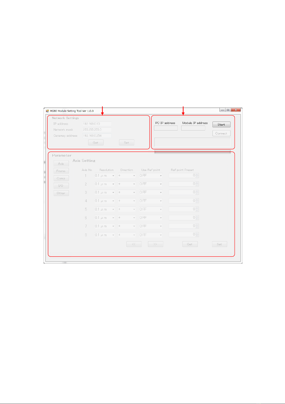
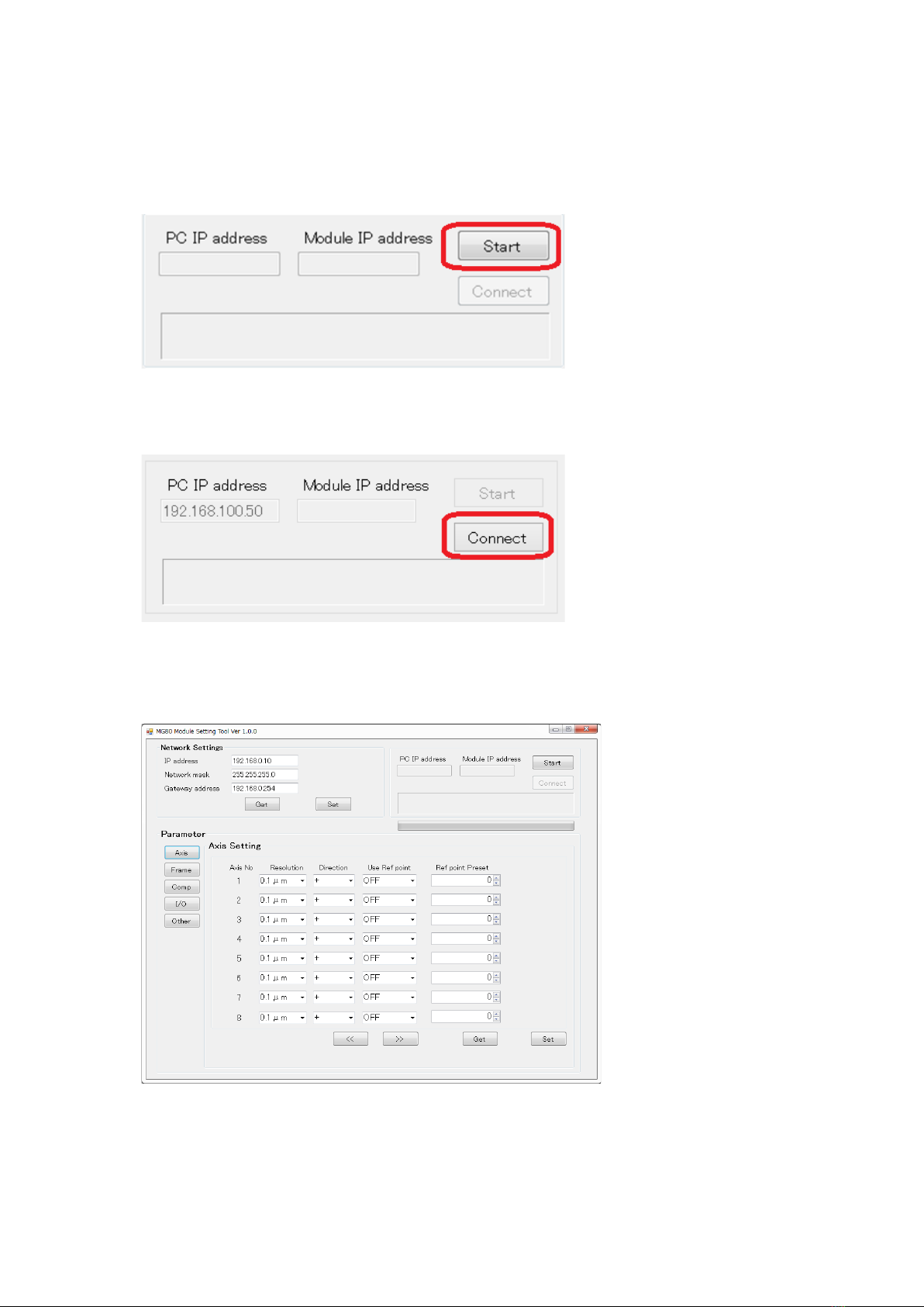
3.3.1. Connecting MG80-EI with PC ............................................................................. 7
3.3.2. Parameter Setting ................................................................................................... 8
3.3.3. Restart MG80-EI ................................................................................................... 15
4. Specifications.................................................................................................................. 16
4.1. Interface specifications ............................................................................................ 16
4.2. LED indicator.............................................................................................................. 17
5. Function ........................................................................................................................... 19
5.1. Function list................................................................................................................ 19
5.2. Frame definition ........................................................................................................ 20
5.3. Detail of function....................................................................................................... 21
5.3.1. Peak hold............................................................................................................. 21
5.3.2. Pause.................................................................................................................... 22
5.3.3. Start ..................................................................................................................... 22
5.3.4. Reset .................................................................................................................... 22
5.3.5. Preset................................................................................................................... 22
5.3.6. Master preset...................................................................................................... 22
5.3.7. Comparator......................................................................................................... 23
5.3.8. Addition/Subtraction ......................................................................................... 23
5.3.9. I/O module control ............................................................................................ 24
6. Communication.............................................................................................................. 25
6.1. Communication with EtherNet/IP device (Scanner) ........................................... 25
6.1.1. Tag data link(Implicit message) .................................................................. 25
6.1.2. CIP communication (Explicit message) .......................................................... 35
6.1.3. CIP communication command list................................................................... 37
6.2. CIP object................................................................................................................... 58
6.2.1. Supported CIP object ........................................................................................ 58

2
6.2.2. CIP Class 0x01 Identity object .......................................................................... 58
6.2.3. CIP Class 0x04 Assembly object...................................................................... 59
6.2.4. CIP Class 0x06 Connection Manager object .................................................... 60
6.2.5. CIP Class 0xF5 TCP/IP Interface object........................................................... 61
6.2.6. CIP Class 0xF6 Ethernet Link object............................................................... 62
6.2.7. CIP Class 0x64 Vendor Specific Class(Bus controller)................................... 63
6.2.8. CIP Class 0x65 Vendor Specific Class(I/O module)........................................ 65
7. Appendix.......................................................................................................................... 67
7.1. Parameter list............................................................................................................. 67
7.2. Status code ................................................................................................................ 70

3
Revision history
Revision
Date
Description
Pages
1.00
2020/04/16
All
1.01
2020/05/18
Corrections of errors and additions
All
1.02
2020/10/12
Corrections of errors
All
1.03
2020/11/16
Add Status code table
71
1.04
2021/05/25
Add Status code table
All

4
1. Overview
MG80-EI is an interface unit main module which enables acquisition of the multi-axis
measurement data by connecting with a PC or PLC via EtherNet/IP communication
protocol. This manual explains the setup procedure and detail of the functions.
For specification of MG80-EI, MG80-CM and LZ80, refer to the instruction manual of
each product. For detail of EtherNet/IP communication with PC or PLC, refer to the
manual of the each manufacturer.

5
2. Basic informaion
EtherNet/IP uses the terms “scanner” and “adapter” in place of “master” and “slave”,
respectively. MG80-EI is the adapter.
This section shows the adapter (MG80-EI) side components and its configuration,
which names and terms also appear in other sections of this manual.
2.1. System configuration
The following diagram shows the example of maximum configuration using MG80
series lineup. A counter module MG80-CM is necessary for a connecting a measuring
unit, and I/O module LZ80-K1/K2 which enables control of the units with external
signal, are available for configuration with MG80-EI.
Scanner
PC, PLC
EtherNet/IP or
Ethernet cable
(MG80-EI side
RJ-45 connector)
Measuring unit
Maximum configuration(1unit)※:
MG80-EI×1, MG80-CM×16, LZ80-K1/K2×2
※Up to 255 units(4080axis) can be connected
Measuring unit No. 1・・・・・・・・・・・15 16
・Up to 16 counter module MG80-CM can be connected to one MG80-EI.
・Connect the measuring unit DK series to MG80-CM.
・Measuring unit numbers are automatically assigned in order from 1 closest to MG80-EI.
・For EtherNet/IP or Ethernet connection, prepare a shielded cable with RJ-45(8P8C) connector.
(Both straight and cross cables can be used.)
・The number of connectable unit depend on the available lower 1byte of the IP address.
If the available IP address is 1 (0x01) to 255(0xFF), maximum of 255units of MG80-EI
(4,080 axes of measuring units) can be connected.

6
3. Setting
3.1. Download setting application and EDS file
1. Access Magnescale Website and download the necessary files.
(https://www.magnescale.com)
Application for Windows PC “MG80SettingTool.exe”
「Products」
→「Digital Gauge」
→「MG80-NE/EI/PN MG80-CM」
→「Software」
Click 「Download」 under “Setting application for Windows PC*2”.
EDS file for EtherNet/IP communication
「Products」
→「Digital Gauge」
→「MG80-NE/EI/PN MG80-CM」
→「Software」
Click 「Download」 under “Setting file*1”.
EDS file can be used regardless of the PLC manufacture and the number of
axes used.
2. Save the files and extract with decompression software.
3.2. About IO data
When EDS file is imported to the development environment, the IO data is
handled as Byte array data. Refer “6. Communication” in this manual for IO data
mapping.
3.3. Setting various parameters
Setting for MG80-EI can be changed with the application for Windows PC
“MG80SettingTool.exe”.

7
3.3.1. Connecting MG80-EI with PC
1. Place the downloaded files in the suitable location of the PC.
2. Set IP address of the PC as shown below.
IP address :192.168.100. xxx※
Subnet mask :255.255.255.0
※Values to avoid in XXX
- “1” (It will be used by MG80-EI in setting mode)
- Same address with other connecting devices.
3. Set MG80-EI IP address switches to “0x00”. This will activate the setting
mode. In this mode, IP address will be fixed as shown below.
IP address :192.168.100.1
Subnet mask :255.255.255.0
4. Connect PC and MG80-EI directly with the Ethernet cable.
Then connect power supply to turn on the MG80-EI.
5. Click “MG80SettingTool.exe” in the PC and start the application.
IP address
Lower 1 byte setting switch: 0x00
LAN (100base-TX)
TCP/IP

8
3.3.2. Parameter Setting
Various parameters can be set with MG80SettingTool.
Following display will show when the software is opened.
Network settings
Connection
Parameter settings

9
Follow the steps below to connect with the MG80-EI.
1. Click the Start button at the top right corner.
2. Click the Connect button.
3. If the connection is successful, “Network settings” and “Parameter” field will
become valid.
If the connection fails, turn off MG80-EI power and close PC application, then restart
the procedure.

10
4. Follow the steps below to change the MG80-EI Network Settings.
The IP address set in this field will be applied in the actual measuring environment.
The lowest 1byte of the IP address (In this case “1”) must also be set with the switches
on the MG80-EI, after setup with this software.
Enter the settings as in red frame above, then click “Set” button to transfer the
information to the MG80-EI.
*Note
IP address = IP address
Network mask = Subnet mask
Gateway address = Default gateway
Click “Get” button to confirm the settings saved in the MG80-EI.

11
3.3.2.1. Measurement parameter setting
Make sure the Parameter field is valid.
If the field is not valid, restart the connection procedure.
If there are multiple pages on the parameter screen, switch pages by pressing the
page forward/backward buttons.
After setting the parameters, click the “Set” button at the bottom of the screen to
save the parameters in MG80-EI.
Note) Make sure to click the “Set” button in each screen, or parameters will not
be save in MG80-EI.
Click “Get” button in the bottom, to make sure the parameters are properly saved.

12
Parameters and Description in the Windows application.
No
Parameters
(Parameter name)
Description
1
Axis
(Axis Setting)
Setting for connected Measuring device. Enter Resolution, Direction, use of
Reference point, and Master preset value of each axis here.
2
Frame
(Frame Setting)
Setting for what data to carry in each Frames. Calculation (Addition,
Subtraction) result of selected axis, Output mode, Preset value of each frame.
3
Comp
(Comparator Setting)
Setting for Comparator. Enter Threshold, Steps, Group to apply on the frame.
4
I/O
(I/O Setting)
Setting for I/O terminal function. Enter function to each of the output terminal.
5
Other
(Other Setting)
Settings other than the above items.

13
(1) Axis Setting screen
(2) Frame Setting screen
Axis number
Select from the pull-down
Input resolution:(0.1, 0.5, 1.0, 2.0, 5.0, 10.0μm)
Direction: Count direction of the measuring unit
Use Ref point: Valid or invalid of reference point detection.
Reference point preset
value (unit: 0.1μm)
Frame number
Select from the pull-down
Ex.1: 1axis +2axis Current value
Ope1(+), Main Axis No.(Axis1 val), Ope2(+), Sub Axis No.(Axis2 val),Mode(Real)
Ex.2: 3axis +4axis Current value
Ope1(+), Main Axis No.(Axis3 val), , Ope2(+), Sub Axis No.(Axis4 val),Mode(Real)
Preset value (Unit: 0.1μm)

14
(3) Comparator Setting screen
(4) I/O Setting screen
Comparator setting
group number
comparator settings
Comparator setting
Click the icon or enter the value manually.
(Unit: 0.1μm)
Set the Steps
(2step/4step)
Select the group
number to be set in the
selected frame.
Select the frame
Input/output setting of the first I/O
module.
Select function from the pull-down.
Input/output setting of the second
I/O module.
Select function from the pull-down.

15
(5) Other Setting screen
3.3.3. Restart MG80-EI
1. After setting all parameters, turn off the power.
2. Set lower 1 byte of the IP address for measurement, by changing the IP address
switches on the MG80-EI.
3. Restart the power to operate with the saved parameters.
Select the output unit of system.
Select from the pull-down.

16
4. Specifications
4.1. Interface specifications
Terms and Functions
Specifications
Switch
and
Indication
Switch
IP address setting
Setting switch×2 pcs. (Hexadecimal output 8bit)
Setting
value
0x00
「Setting mode」
IP address will be fixed to 192.168.100.1
0x01
~
0xFF
「IP address setting for measurement」
Set lower 1byte of IP address with switches.
Example:
Set the upper 3bytes of the IP address with
Windows application to 192.168.0.__., then turn
the IP address setting switches to “A” for
192.168.0.”10.”
Indication
LED lamp status
Refer to 4.2 LED indicator
Communi-
cation
I/F
LAN connector
RJ-45×2(100BASE-TX)
Shielded cable.
EtherNet/IP
communication
・Transmits the count value, error status, and calculation result
obtained from the measuring unit.
・Receives commands from the host device.
・The communication standard is the EtherNet/IP specification.
TCP/IP communication
・When switches are set to “0x00”, MG80-EI enters “Setting mode”
with IP address fixed to 192.168.100.1. for TCP/IP communication.
This allows IP address and parameters to be changed, using
application for Windows PC.
Power
FG ×1
+V ×1
0V ×1
Terminal ×1
(3 pole)
All modules and measuring units connected to MG80-EI are supplied
from this power supply terminal.

17
4.2. LED indicator
The function of LED display is described below.
[PWR] Power LED :Displays the operation status of this module
Color
Status
Contents
Green
Off
Power off
On
Ready for operation after power on
[ALM] Alarm LED :Displays the alarm status of all modules.
Color
Status
Contents
Red
Off
Normal operation
On
Lights when an alarm occurs on any module.
[HOLD] Hold LED :Displays Hold status
Color
Status
Contents
Orange
Off
All count data is released from hold.
On
Any count data is in hold status.
[MS]Module status LED :Displays the module status according to the EtherNet/IP standard.
Color
Status
Contents
-
Off
Power off or no IP address
Green
On
RUN status
Flashing
IDLE status
Red
On
Error status
Flashing
Recoverable failure is occurred.
[NS]Network status LED :Displays the network status according to the EtherNet/IP standard.
Color
Status
Contents
-
Off
Power off or no IP address
Green
On
Connection established
Flashing
Connection not established
Red
On
The IP address is duplicated. Fatal error occurred.
Flashing
Connection timed out

18
Communication port status LED
Displays the link status of communication port 2
Color
Status
Description
Green
Off
Link not established
On
Link established
Displays the link speed of communication port 2
Color
Status
Description
Orange
Off
Abnormal communication speed
On
Communication speed is normal
Displays the link status of communication port 1
Color
Status
Description
Green
Off
Link not established
On
Link established
Displays the link speed of communication port 1
Color
Status
Description
Orange
Off
Abnormal communication speed
On
Communication speed is normal

19
5. Function
5.1. Functions list
Item
Contents
Condition
Module configuration
Whole system
MG80-EI can be expanded to 255 units via EtherNet/IP network (total 4080axes)
Number of
connectable modules
Counter module MG80-CM:From 1 to 16units (Measuring unit 1 to 16 axes)
I/O module LZ80-K1/K2:Max. 2units
Resolution
Measuring unit
Input resolution
0.1μm/0.5μm/1μm/2μm/5μm/10μm
Data capture capability
10Mbps
Max. 10000 data/sec.
Data format
7-digit fixed length with sign and decimal point
(Top zero suppress)
Peak hold function
Stores the maximum value, minimum value, and peak-to-peak(max-min) values of each
frame.
Hold updating peak value during pause period.
Starts recalculation of the peak value with start command or I/O input.
Output mode
Single axis
Current(real) value, maximum value, minimum value, peak to peak value of each axis
Addition and
subtraction function
Current(real) value, maximum value, minimum value, peak to peak value of 2-axis added
or subtracted.
Comparator
A measurement data in frame* compared with the thresholds, and output areal
information in a number.
Number of steps
2 steps/4 steps
Number of groups
8 groups
Reset
Reset count value to zero
Reference point
Geometrical point on measuring device with signal output.
Combine with Master preset function for an absolute mode.
Preset
Overwrite the current frame value to the Preset value by command.
Master preset
A preset value with relative position from the reference point memorized.
When restarting, Master preset value will be called.
I/O module
A function can be assigned to each terminal of the I/O module.
Input and ouput will be performed accordingly.
※ “Frame” is a original term for data transfer in Explicit communication. It
can be arranged to carry measurement or calculated value of the any
selected units. Details are explained in next page (5.2).
Table of contents