manuals.online logo
Brands
  1. Home
  2. •
  3. Brands
  4. •
  5. Magnetek
  6. •
  7. Industrial Electrical
  8. •
  9. Magnetek IMPULSE G+ Mini User manual

Magnetek IMPULSE G+ Mini User manual

Other manuals for IMPULSE G+ Mini

1

Other Magnetek Industrial Electrical manuals

Magnetek LaserGuard Mini User manual

Magnetek

Magnetek LaserGuard Mini User manual

Magnetek ELECTROBAR FS User manual

Magnetek

Magnetek ELECTROBAR FS User manual

Popular Industrial Electrical manuals by other brands

Murata GRM0335C1E3R9BA01 Series Reference sheet

Murata

Murata GRM0335C1E3R9BA01 Series Reference sheet

ARCAIR N6000 Automatic System Safety and operating instructions

ARCAIR

ARCAIR N6000 Automatic System Safety and operating instructions

Murata GRM31CR61E106MA12 Series Reference sheet

Murata

Murata GRM31CR61E106MA12 Series Reference sheet

Murata GQM2195C2A9R1CB01 Series Reference sheet

Murata

Murata GQM2195C2A9R1CB01 Series Reference sheet

MFJ MFJ-918 quick start guide

MFJ

MFJ MFJ-918 quick start guide

Abtech HVJB Series Installation, operation & maintenance instructions

Abtech

Abtech HVJB Series Installation, operation & maintenance instructions

Murata GRM0335C1H8R1DA01 Series Reference sheet

Murata

Murata GRM0335C1H8R1DA01 Series Reference sheet

SAF-HOLLAND CBX 5415.5 Installation and operation manual

SAF-HOLLAND

SAF-HOLLAND CBX 5415.5 Installation and operation manual

Eaton Ulusoy HMH24-04 user manual

Eaton

Eaton Ulusoy HMH24-04 user manual

Murata GJM0335C1E4R4BB01 Series Reference sheet

Murata

Murata GJM0335C1E4R4BB01 Series Reference sheet

Newlong NP-7H NSTRUCTION MANUAL/PARTS LIST

Newlong

Newlong NP-7H NSTRUCTION MANUAL/PARTS LIST

Stahl 8575/12 operating instructions

Stahl

Stahl 8575/12 operating instructions

SI Pegasus installation instructions

SI

SI Pegasus installation instructions

Murata GRM1555C1H2R7CA01 Seies Reference sheet

Murata

Murata GRM1555C1H2R7CA01 Seies Reference sheet

Murata GRM0225C1E6R4BA03 Series Reference sheet

Murata

Murata GRM0225C1E6R4BA03 Series Reference sheet

Cooper Power Systems VXE15 Installation and operation instructions

Cooper Power Systems

Cooper Power Systems VXE15 Installation and operation instructions

S&C Vista SD manual

S&C

S&C Vista SD manual

Murata GRM0335C2A7R3CA01 Series Reference sheet

Murata

Murata GRM0335C2A7R3CA01 Series Reference sheet

manuals.online logo
manuals.online logoBrands
  • About & Mission
  • Contact us
  • Privacy Policy
  • Terms and Conditions

Copyright 2025 Manuals.Online. All Rights Reserved.

OVERVIEW
The following procedure is a supplement to other documentation available
for the IMPULSE•G+ Mini variable frequency drive (VFD). This will guide
the user in proper installation and setup of the system. Before using the
VFD-controlled equipment, the operator shall read the operating manual of
the hoisting machine, shall be trained, and has to know all hazards by
operating of cranes, hoists, or lifting devices.
When installing the system, be sure to follow good wiring practices and
follow all applicable electrical codes. Ensure that the mounting of all
components are secure and the environment, such as excessive moisture,
poor ventilation, etc., will not cause system degradation.
Read this document thoroughly before attempting installation. Refer to the
technical manual available at: www.columbusmckinnon.com/magnetek.
Step 1
Connect Motor and Line Power
Figure 1 shows the electrical connections for the input power and motor
terminals on the IMPULSE•G+ Mini. Make the appropriate connections,
with power turned off. Follow good wiring practices and follow all applicable
electrical codes. Ensure the equipment is properly grounded, as shown.
Figure 1: Input Power and Output Motor Connections
DANGER! DANGEROUS VOLTAGES ARE PRESENT WHEN VFD IS
ON. Improper wiring can cause bodily harm and damage to the
equipment. Before applying power to the IMPULSE•G+ Mini,
ensure that all protective covers are fastened and all wiring con-
nections are secure. After power has been turned OFF, wait at
least 5 minutes until the charge indicator extinguishes completely
before touching any wiring, circuit boards, or components.
WARNING: DO NOT CONNECT ANY OF THE FOLLOWING
TERMINALS TO EARTH GROUND.
THREE PHASE
INPUT
IMPULSE•G+
MINI
B1 B2 – + +1 +2
R/L1 S/L2 T/L3 U/T1 V/T2 W/T3
(R/L1) (S/L2) (U/T1) (V/T2)(T/L3)
(W/T3)
Input
Protection
(Fuse or C.B.)
Connect to
chassis
ground
To change direction of
motor rotation, swap any
two of the three motor
leads (See Step 1)
L1 L2 L3
3Ø Input Power
Connect
frame to
ground
3Ø Induction
motor
Step 2
Typical Connection Diagram
This step shows a typical wiring diagram and connection points for the
IMPULSE•G+ Mini. Wiring connections should only be made by trained and
authorized personnel when power to the VFD is turned off.
* 24VDC interface is standard. 120VAC, 42-48VAC, and 24VAC is optional.
** Optional P3S2-OUT2 card provides two 240 VAC, 1.5 Amp solid-state relay outputs
(panel-mounted).
*** In accordance with UL508C, ISO 13849-1 (Cat. 3, PL d), and EN 61800-5-2 (SIL2).
Figure 2: Typical Connection Diagram
Step 3
Changing Parameters and Monitoring
This step shows how to access and modify a parameter as well as how to monitor
signals such as output frequency and motor current.
Make sure all protective covers have been re-attached and power is turned on.
DO NOT RUN THE MOTOR.
Access Parameter Menu and Change Parameters
Figure 3: Digital Operator Power-up State
Press until the digital operator shows the parameter menu (PAr) then press
.
Figure 4: Select Parameter Menu
Press to select the digit you would like to change. Next use and to
select the parameter group, sub-group, or number.
Figure 5: Select Parameter
Modify the parameter value using and . Press to save.
Figure 6: Change Parameter Value
Press ESC several times to return to the main display.
N49 W13650 Campbell Drive
Menomonee Falls, WI 53051
Phone: 262.783.3500
Fax: 262.783.3510
Toll-Free Phone: 800.288.8178
Toll-Free Fax: 800.298.3503
For questions regarding service or technical information contact:
1.833.SVC.CMCO (1.833.782.2626)
International Service
Outside the U.S. & Canada call 1.262.783.3500, press 3
www.columbusmckinnon.com/magnetek
IMPULSE•G+ Mini Quick Start Guide
144-25543 R1
August 2020 © Copyright 2020 Magnetek
IMPULSE®•G+ Mini Variable Frequency Drive
Quick Start Guide
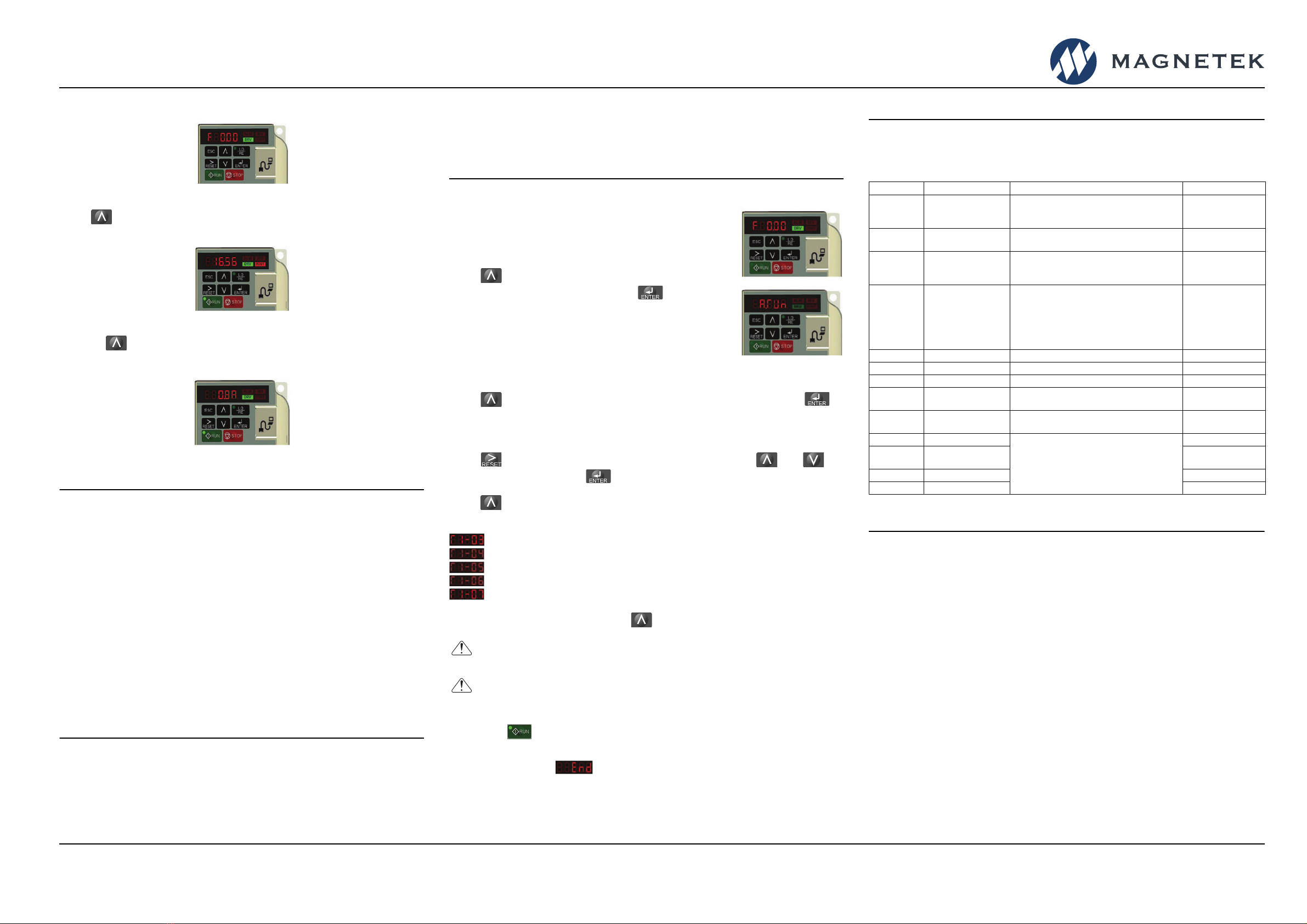
Monitor Motor Frequency and Motor Current
Figure 7: Digital Operator Main Display
Press until the FOUT LED turns on. The display now shows the actual
output frequency in Hz.
Figure 8: Output Frequency
Pressing again will show the motor output current in Amps.
NOTE: Refer to the technical manual on how to access other drive monitors.
Figure 9: Motor Current
Step 4
Select a Control Method and Motion
This step explains how to configure the VFD for a Hoist or Traverse
application. For hoisting applications, the IMPULSE•G+ Mini should only be
used to control a hoist with a mechanical load brake.
Traverse:
Set parameter A01.03 = 0 (Traverse).
It is recommended that the Control Method is set to V/f (A01.02 = 0).
If Open Loop Vector is desired, set A01.02 = 2.
Hoist (with Mechanical Load Brake):
Set parameter A01.03 = 1 (Hoist).
It is recommended that the Control Method is set to V/f (A01.02 = 0).
If Open Loop Vector is desired, set A01.02 = 2.
NOTE: An Auto-tune is recommended when using the Open Loop Vector
control method or Hoist motion.
Step 5
Select a Speed Reference
This step lists the speed reference settings that are selected with parameter
A01.04.
NOTE: Default speed settings will be automatically applied via X-Press
Programming™. Reference the technical manual for more details and wiring
instructions.
Step 6
Auto-Tuning with Motor
In this step the IMPULSE•G+ Mini is set up for use with the
motor. Make sure all protective covers have been re-
attached and then apply power to the IMPULSE•G+ Mini.
DO NOT RUN THE MOTOR.
Press until the Digital Operator shows the
Auto-Tuning menu (A. Tun) then press .
V/f:
Set T01.01 = 2 (Term Resistance)
Open Loop Vector:
Decouple motor from load and disengage brake.
Set T01.01 = 0 (Standard Tuning)
Press until the Digital Operator shows parameter T01.02 then press .
For Europe: Enter Motor Power in kW
For USA: Enter Motor Power in HP
Press to select the digit you would like to change and use and to
adjust the value, then press to save the value.
Press to select the next parameter and follow the same procedure described
above to adjust its value.
After setting parameter T01.07 press to select the Auto-Tuning command.
Next, press on the Digital Operator. The IMPULSE•G+ Mini will now start the
Auto-Tuning procedure.
The display will show when the Auto-Tuning procedure has successfully
completed. Please reference the IMPULSE•G+ Mini technical manual or repeat
Auto-Tuning procedure if the display shows an error message.
2-Speed Multi-Step: A01.04 = 0 2-Step Infinitely Variable: A01.04 = 3
3-Speed Multi-Step: A01.04 = 1 3-Step Infinitely Variable: A01.04 = 4
5-Speed Multi-Step: A01.04 = 2 Uni-Polar Analog: A01.04 = 5
Motor Rated Voltage (e.g. 230 V, 460 V)
Motor Rated Current (e.g. 22.0 A)
Motor Rated Frequency (e.g. 60.0 Hz)
Motor Poles (e.g. 4 Poles)
Motor Rated Speed (e.g. 1750 rpm)
WARNING! SUDDEN MOVEMENT HAZARD. The IMPULSE•G+
Mini and motor may start unexpectedly during Auto-Tuning.
WARNING! ELECTRIC SHOCK HAZARD. High voltage will be
supplied to the motor when Auto-Tuning is performed. Do not
touch the motor.
Step 7
Quick Start Parameters
The following table lists the commonly used parameters as well as frequently
asked questions.
Frequently Asked Questions
Question: How do I reset the drive back to factory default settings?
Answer: Go to parameter A01.05 and enter 1110.
Question: How do I adjust the time it takes the motion to speed up or slow down?
Answer: Adjust the acceleration time parameter B05.01 and deceleration time
parameter B05.02.
Question: How do I prevent my drive from tripping on an OV fault (overvoltage)
while my motor is ramping down?
Answer:
Increase deceleration time parameter B05.02 and check braking resistor.
Question: How do I prevent my drive from tripping on an OL1 fault (overload)
while my motor is ramping down?
Answer: Verify motor rated current parameter E02.01 and motor overload
protection time parameter L01.02.
Question: How can I run my motor above the nominal motor speed?
Answer: Increase the value of parameter E01.04 Maximum Frequency.
Verify that the motor and system allow for this.
Question: How can I change motor direction without changing the motor leads?
Answer: Set parameter B03.04 to 1 (exchange phases).
Question: Where can I find troubleshooting information regarding faults and
alarms?
Answer: Reference the technical manual.
Parameter Description Settings Comments
A01.01 Access Level
0 = User
1 = Basic
2 = Advanced
A01.02 Control Method 0 = V/f
2 = Open Loop Vector*
* Auto-Tune
recommended
A01.03 Motion
0 = Traverse
1 = Hoist
4 = Braketronic
A01.04 Speed Reference
0 = Two-Speed Multi-Step
1 = Three-Speed Multi-Step
2 = Five-Speed Multi-Step
3 = Two-Step Infinitely Variable
4 = Three-Step Infinitely Variable
5 = Uni-Polar Analog (0-10VDC, 4-20mA)
B01.01 - 16 Speed References 0.00 - 150.00 Hz Limited by E01.04
B05.01 Acceleration Time 0.0 - 25.5 Seconds
B05.02 Deceleration Time 0.0 - 25.5 Seconds
E01.01 Input Voltage 155 - 255 VAC (200 VAC Models)
310 - 510 VAC (400 VAC Models) Line Voltage
E02.01 Motor Rated FLA 0.01 - 70.0 Amps See Motor
Nameplate
H01.xx Digital Inputs
See Technical Manual for Options
Terminals S1 - S7
H02.xx Digital Outputs Terminals MA/MB,
P1, P2
H03.xx Analog Inputs Terminals A1, A2
H04.xx Analog Output Terminal AM
N49 W13650 Campbell Drive
Menomonee Falls, WI 53051
Phone: 262.783.3500
Fax: 262.783.3510
Toll-Free Phone: 800.288.8178
Toll-Free Fax: 800.298.3503
For questions regarding service or technical information contact:
1.833.SVC.CMCO (1.833.782.2626)
International Service
Outside the U.S. & Canada call 1.262.783.3500, press 3
www.columbusmckinnon.com/magnetek
IMPULSE•G+ Mini Quick Start Guide
144-25543 R1
August 2020 © Copyright 2020 Magnetek
IMPULSE®•G+ Mini Variable Frequency Drive
Quick Start Guide