INSTALLATION GUIDE
X-SERIES
120VAC / 12/24VAC / 1000-1200W
Magnitude, Inc. Page 2of 2
14711
Bentley
Circle.
T
ustin,
CA
92780
www
.MagnitudeInc.com
[email protected] DOC-GU-
XXXXX Rev
.
1
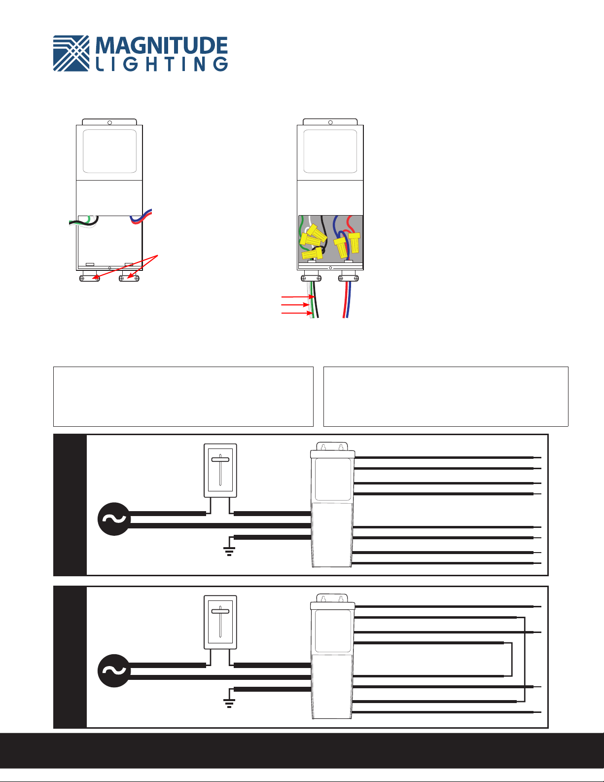
Wiring Diagram
2With power turned off, route the
input wires through a strain relief
and connect one wire to black
and one wire to white. for all wire
connections use only UL listed
wire nuts and connectors of
suitable size and type. Connect
the ground wire to the transformer
green wire.
34
Strain Reliefs
OutputInput
Output Connections
Bring the wires of the light xture through
the other clamp connector and connect
them to the driver wires - positive to the
(+ ) wire and negative to ( - ) wire. See
diagrams below for wire color specics.
Measuring the output voltage without a
load will result readings greater than the
nominal voltage.
The transformer case MUST be
grounded in accordance with the N.E.C
Black
White
Green
Red Wire
Red Wire
Yellow Wire
OUTPUT
24VAC / 26VAC Boost
Yellow Wire
Purple Wire
Purple Wire
Blue Wire
Blue Wire
INPUT
120V AC 60Hz
Dimmer
(Optional)
Green Wire
Ground
Red Wire
Red Wire
Yellow Wire
Input Wire (Black)
Input Wire (White)
OUTPUT
12VAC / 13VAC Boost
INPUT
120V AC 60Hz
Dimmer
(Optional)
Green Wire
Ground
Input Wire (Black)
Input Wire (White)
Yellow Wire
Purple Wire
Purple Wire
Blue Wire
Blue Wire
12V24V
Dimming
Dimmable with any standard MLV / Incandescent TRIAC (Leading edge)
dimmer switch. Dimmer switch is to be installed on the input (120VAC side) of
the driver. For smooth dimming, 8W minimum load is required. Please visit our
website for a full dimmer compatibility list www.magnitudeinc.com
Boost-Tap
The Orange Boost-Tap wire is an optional 10% voltage boost, which can
compensate for voltage drop between the driver and the xture. If the
xture is receiving 10.5V (21.5V for 24V xtures) or less we recommend
substituting the black wire for the orange boost-tap wire.


