Magnum 232751 Instruction Manual

Graco Inc. P.O. Box 1441 Minneapolis, MN 55440-1441
Copyright 2002, Graco Inc. is registered to I.S. EN ISO 9001
3Z9478A
Operation/ /
XR9 Airless Sprayer
YS:!
zt[BcBu
Models/ / :
232751, 232752, 232753 - Series A/B! /Bc
Maximum Working Pressure/ /B B L: 207 bar, 21 MPa (3000 PSI)
Includes/ /B:
• 1.44 lpm (0.38 gpm) cart-mount sprayer/2/55!mqn!)1/49!hqn*! /
SPVVBBJRPUZBKB B B
• SG3E/A gun/TH4F0B! !.! 041:1:8/uiUgQcB BOB QUR[R[Y
• 0.635 cm (1/4 in) x 15.2 m (50 ft) hose/1/746!dn!)205!jo*!y!26/3!n!)61!gu*! /
RPXUWBBJSQVB KBBSWPTBBJWRB KB
ti2017a

Table of Contents/ /
23Z9478A
Table of Contents/ /
Table of Contents/ /B PBPBPBPBPBPBPBPBPBPBPBPBPBPBPBPBPBPBPBPBPBPBPBPBPBPBPBPBP T
Warning . . . . . . . . . . . . . . . . . . . . . . . . . . . . . . . . . . . . . . . . . . . . . . . . . . . . . . . . . . . . . . . . . . . . .3
! /!/!/!/!/!/!/!/!/!/!/!/!/!/!/!/!/!/!/!/!/!/!/!/!/!/!/!/!/!/!/!/!/!/!/!/!/!/!/!/ 4
B PBPBPBPBPBPBPBPBPBPBPBPBPBPBPBPBPBPBPBPBPBPBPBPBPBPBPBPBPBPBPBPBPBPBPBPBPBPBPBP V
Pressure Relief/ /BB BPBPBPBPBPBPBPBPBPBPBPBPBPBPBPBPBPBPBPBPBP [
Grounding and Electrical Requirements/ /B B B BPBPBPBPBPB SR
Component Identification/ /BB PBPBPBPBPBPBPBPBPBPBPBPBPBPBPBPBPBPBPB ST
Setup/ /B PBPBPBPBPBPBPBPBPBPBPBPBPBPBPBPBPBPBPBPBPBPBPBPBPBPBPBPBPBPBPB SV
Priming/ /BBPBPBPBPBPBPBPBPBPBPBPBPBPBPBPBPBPBPBPBPBPBPBPBPBPBPBPBPBPB SW
Spraying Techniques/ /BB PBPBPBPBPBPBPBPBPBPBPBPBPBPBPBPBPBPBPBPB SY
Cleanup/ /B PBPBPBPBPBPBPBPBPBPBPBPBPBPBPBPBPBPBPBPBPBPBPBPBPBPBPBPBPBPBPBPB TR
Troubleshooting . . . . . . . . . . . . . . . . . . . . . . . . . . . . . . . . . . . . . . . . . . . . . . . . . . . . . . . . . . . . . .34
! /!/!/!/!/!/!/!/!/!/!/!/!/!/!/!/!/!/!/!/!/!/!/!/!/!/!/!/!/!/!/!/!/!/!/!/!/! 49
BB BPBPBPBPBPBPBPBPBPBPBPBPBPBPBPBPBPBPBPBPBPBPBPBPBPBPBPBPBPBPBPBPBPBPBPBPB VT
Maintenance/ /B PBPBPBPBPBPBPBPBPBPBPBPBPBPBPBPBPBPBPBPBPBPBPBPBPBPBPBPB VX
Technical Data/ /BB BPBPBPBPBPBPBPBPBPBPBPBPBPBPBPBPBPBPBPBPBPBPBPB WU
Graco Standard Warranty/Hs dp! /iB BB BPBPBPBPBPBPBPBPB WX

Warning
3Z9478A 3
WARNING
Fire, Explosion and Electrocution
Hazard
Improper grounding, poor air ventilation, open
flames, or sparks can cause a hazardous condi-
tion and result in fire, explosion, or electric shock.
To help prevent these hazards:
•Sprayer should be grounded through an elec-
trical outlet as follows:
- Only use grounded electrical outlets.
- Only use 3-wire extension cords.
- Grounded prongs must be intact on sprayer
and extension cords.
•Keep electrical connections and inside of
shroud dry.
•Avoid contact with power lines.
•Use outdoors or in well-ventilated area.
•Sprayer should be at least 6m (20 ft) from gun
when spraying or flushing.
•If there is any static sparking while using
equipment, stop spraying immediately.
Identify and correct the problem.
•Avoid all ignition sources such as pilot lights,
cigarettes and plastic drop cloths (static arc
hazard).
•Do not plug in or unplug power cords or turn
lights on or off in spray area.
•Only use Graco airless paint hoses.
•
.!
.!
.!
•
•
•
•!
731!
•
•
!
•
•!Hs dp! !

43Z9478A
NB B B B
BNB BNB B B B
BNB NB B B B B
B P
B B \
•B B B B B
B P
OB B B B P
OBU B B B P
OB B B B B B
B B P
•B B B B B B
B P
•B B P
•B B B B B
P
•B B B B
BXBJTRB KB B B
P
•B B B B B B
BB B B B B
B B P
•NB NB B J B B KB
B B B B B B B
P
•B B B B B
BNB B B B P
•iB B B B
PB

3Z9478A 5
WARNING
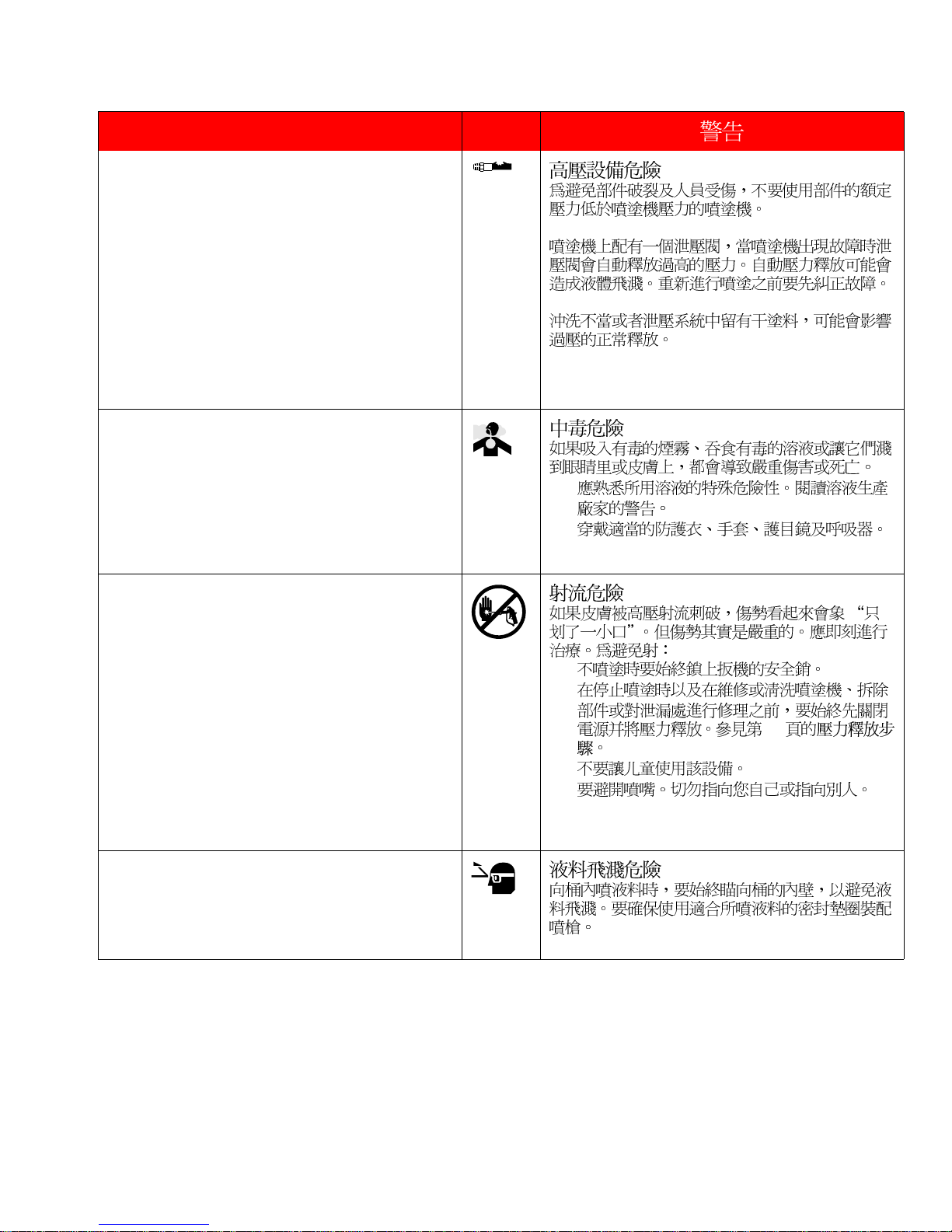
Pressurized Equipment Hazard
To avoid component rupture and injury, do not
operate sprayer with components rated less than
pressure of sprayer.
Sprayer is equipped with a pressure drain that
automatically relieves overpressure in the event of
a fault condition. This automatic pressure relief
may cause splashing fluid. Correct fault before
you resume spraying.
Inadequate flushing and/or dried paint in drain
system may prevent proper overpressure relief.
Toxic Fluid Hazard
Hazardous fluids or toxic fumes can cause serious
injury or death if splashed in eyes or on skin, swal-
lowed, or inhaled.
•Know specific hazards of fluid being used.
Read fluid manufacturer’s warnings.
•Wear appropriate protective clothing, gloves,
eyewear, and respirator.
•
•
Fluid Injection Hazard
If high-pressure fluid pierces skin, the injury might
look like “just a cut”but it is a serious wound. Get
immediate medical attention. To help prevent
injection:
•Always engage trigger safety when not spray-
ing.
•Always shut off power and relieve pressure
when you stop spraying, before you service or
clean sprayer, remove parts or repair leaks.
See Pressure Relief Procedure, page 9.
•Do not allow children to use this equipment.
•Keep clear of tip. Never point at yourself or
anyone else.
•
•
!:!
•
•.
Fluid Splashback Hazard
To avoid splashing fluid when spraying into pail,
always aim at inside wall of pail. Make sure gun is
assembled with correct gasket for fluid being
sprayed.

63Z9478A
B B
B B B B NB
B B B B B B
B B P
BBBB BBB
B B B B B PB
B B B B B B
PB B B B B B B
P
B B B B B B
B B B B B B
B P
B B B
BBBBBBB
B B B B B B
B B P
•B B B B
B B P
•BNB BNB B B
B P
BBB
B B B B B B
B B B B B B
PB B B B B B
PB B B \
•B B B B B
BPB
•B B B B
B B B B B
B B B B B B
BPB[ BB
B P
•B B B B P
•B B B B B
B B P
B B
B B B B B B B
B B B PB B
B B B B B
B P

3Z9478A 7
WARNING
Recoil Hazard
Due to the high pressure fluid emitted, a strong
recoil action may occur when you trigger the
gun. If you are unprepared, your hand could be
forced back toward your body or you could lose
your balance and fall, resulting in serious injury.
Equipment Misuse Hazard
Equipment misuse can cause equipment to rup-
ture, malfunction, or start unexpectedly and
cause serious injury.
•Read all manuals, tags, and labels before
operating equipment.
•Only use equipment for its intended pur-
pose.
•Do not alter or modify equipment.
•Do not exceed maximum working pressure
of lowest rated system component.
•Do not modify extension tube or roller frame
or use parts not designed for this equipment
•Do not use 1,1,1-trichloroethane, methylene
chloride, other halogenated hydrocarbon
solvents or fluids containing such solvents in
this or any other pressurized aluminum
equipment. Such use could result in a chem-
ical reaction, with the possibility of explosion.
•
•
•
•
!
•
•
2-2-2.
Startup Hazard After Thermal
Overload
Motor has thermal overload switch to shut itself
down if overheated. To reduce risk of injury from
motor restarting unexpectedly when it cools,
always turn power switch OFF if motor shuts
down.

83Z9478A
B
B B B B B B B
B B B B PB B B
B B B B B B
B B B B B P
B B
B B B B B
B B B B B B B
B P
•B B B B NB B
B B P
•B B B P
•B B B P
•B B B B B B B
B B B B B
P
•B B B B B B
B B B B
B P
•B B B B B B
BSPSPSO NB BNB B
B B B B B
B B B B PB
B B B B B
B B B B B P
B B B B
B B B B B B B
BBB PB B
B B B B B
B B B B B B
B B P

Pressure Relief/ /B
3Z9478A 9
Pressure Relief/ /B
WARNING/ /
Page/ !/5.
1. Turn OFF power switch.
B P
2. Place prime tube in waste pail.
B B B B P
3. Turn Prime/Spray valve to PRIME.
0QSJNF
Q B B tkog B P
4. Turn pressure control knob left (minimum pressure).
B B J B K B P
5. Trigger gun into bucket to relieve pressure in hose.
B B B B B B P
ti2018a
ti2034a
ti2019a
ti2020a
ti2033a

Grounding and Electrical Requirements/ /B B B
10 3Z9478A
Grounding and Electrical Requirements/ /B B B
A. This sprayer requires 220-240 VAC, 50/60 Hz 10A circuit with
a grounding receptacle. Never use an outlet that is not
grounded.
!331.351!W-!61071!I{!
21B!
B B B B TTROTVRBxceNB
WRQXR j BSRcB BPB B B
B B P
B. Do not use sprayer if electrical cord has damaged ground
prong.
B B B B B B B
B P
ti10-a
t10-*b

Grounding and Electrical Requirements/ /B B B
3Z9478A 11
C. Do not use an extension cord with damaged ground plug.
Recommended extension cords:
•15 m (49.2 ft) 1.0 mm2
•30 m (88.4 ft) 1.5 mm2
•50 m (164.0 ft) 2.5 mm2
•26!n!)5:/3! *!2/1!nn
3
•41!n!)99/5! *!2/6!nn
3
•61!n!)275/1! *!3/6!nn
3
B B B B B B P
B B \
•SWBBJV[PTBKBSPRB
T
•URBBJZZPVBKBSPWB
T
•WRBBJSXVPRBKBTPWB
T
Smaller gauge or longer extension cords may reduce sprayer performance.
B B B B B B B B B B P

Component Identification/ /B
12 3Z9478A
Component Identification/ /B
B
J
W
A
X
H
L
G
KF
ED
C
P
M
U
T
V
S
R
Q
ti2023a

Component Identification/ /B
3Z9478A 13
Component/ /
AElectric motor (inside enclosure)/ /B J K
BPower switch/ /B
CPressure control knob/ /B
DPump fluid outlet fitting/ /B B B
EInstaClean™fluid filter/ Jotu Dmf o™!/ke BBB
FPower-Piston™pump (behind Easy Access door)/Qpxfs.Qjtupo™!/
O BBJ B B B K
GSuction tube/ /B
HPrime tube (with diffuser)/ /B J B K
JPrime/Spray valve control/ 0 0 /Q Q B B
KFluid inlet connection and inlet valve/ /B B B B B
LInlet screen/ /B
MPaint hose/ /B
PSG3E/A airless spray gun/TH4F0B! /uiUgQcB B B
QTip guard/ /B
RReversible spray tip/ /B B
STrigger safety lever/ /B B
TGun fluid inlet fitting/ /B B B
USmooth Glide™swivel/Tnppui!Hmjef™!/uBi B B
VGun fluid filter (in handle)/ ) */B B J B K
WHose/cord wrap bracket/ 0/Q B B
XPail hanger/ /B
YPower Flush attachment (included)/ /B B J K

Setup/ /
14 3Z9478A
Setup/ /
1. Turn OFF power switch.
B P
2. Connect one end of grounded fluid hose to SG3E/A spray
gun. Use a wrench to tighten.
!TH4F0B!
BB BBBuiUgQcB B
B B NB B B P
3. Connect other end of hose to sprayer fluid outlet fitting. Use
wrench to tighten.
Connect other end of hose to sprayer fluid outlet fitting. Use
wrench to tighten.
BBBBBBBBNB
B B P
4. Turn pressure control knob left (minimum pressure).
B B J B K B P
ti2018a
ti2024a
ti2025a
ti2020a

Priming/ /
3Z9478A 15
For flushing storage fluid and loading pump and hose with paint.
B B B B B B B \
Priming/ /
Before priming sprayer, follow Pail Flushing procedure, Steps 1-6, page 24.
!24!!2.7!
B B B B B J24 BSOXB K B P
1. Turn OFF power switch.
B P
2. Submerge suction tube in paint.
B B B P
3. Turn Prime/Spray valve to PRIME.
0QSJNF
Q B B tkog B P
4. Point gun into waste pail.
B B B B P
ti2018a
ti2026a
ti2019a
ti2027a

Priming/ /
16 3Z9478A
5. Turn ON power switch. Align arrow on sprayer and bucket
symbol on pressure control knob.
BPB B B B B B
B B B P
WARNING/ /
Page/ !/5.
6. When paint, without bubbles, starts to come out of prime tube,
trigger gun and turn Prime/Spray valve to SPRAY. When paint
comes out of gun, release trigger.
0TQSBZ
B B B B B B B
B B B Q B B
u tc{ B B NB B B B B
P
The motor stopping indicates the pump and hose are primed with paint.
B B B B B B B P
7. Transfer prime tube to paint pail.
B B B P
ti2028a
ti2029a
ti2030a

Spraying Techniques/ /B
3Z9478A 17
Pressure Adjustment/ /B
Spraying Techniques/ /B
WARNING/ /
Page/ !/3, 5.
Motor runs only when gun is triggered. Sprayer is designed to stop pumping when gun trigger is released.
B B B B PB B B B B B B B
B P
.Align arrow on sprayer with spray symbol on pressure control
knob.
B B B B B B
B P
.Turning knob right (clockwise) increases pressure at gun.
B B J B KB B
B P
ti2031a
ti2032a

Spraying Techniques/ /B
18 3Z9478A
Getting Started with Basic Techniques/
/
B B B
.Turning knob left (counterclockwise) decreases pressure at
gun.
B BJBBKB B
B P
.Hold gun 30 cm (12 in.) from surface and aim straight at sur-
face. Tilting gun to direct spray angle causes an uneven finish.
!41!dn!)23! *
URJSTB KB B B B B
BPB B B B B
B B B B P
.Flex wrist to keep gun pointed straight. Fanning gun to direct
spray angle causes uneven finish.
B B B B B B
PB BBBB
B B B B B P
ti2020a
ti2035a
ti2036a

Spraying Techniques/ /B
3Z9478A 19
Triggering Gun/ /B B
Aiming Gun/ /B
.Pull trigger after starting stroke, release trigger before end of
stroke. Gun must be moving when trigger is pulled and
released.
B B B B NB B
B B B PB B B B
B B B B B P
.Aim tip of gun at edge of previous stroke to overlap each
stroke by half.
B B B B B B
B B B B B B P
ti2037a
ti2038a

Cleanup/ /
20 3Z9478A
Power Flush - Quick Cleaning/ !.! /
B B-B B
For flushing water-based fluids only.
B B
Cleanup/ /
1. Turn Prime/Spray valve to PRIME.
0QSJNF
Q B B tkog B P
2. Separate prime tube from suction tube.
B B B B P
3. Unscrew inlet screen from suction tube.
B B B B B P
4. Place prime tube in waste pail.
B B B B P
ti2019a
ti2039a
ti2040a
ti2034a
This manual suits for next models
2
Table of contents
Other Magnum Paint Sprayer manuals

Magnum
Magnum XR9 Instruction Manual

Magnum
Magnum 232735 Use and care manual

Magnum
Magnum 261805 User manual

Magnum
Magnum TexFinish 246185 Operating instructions

Magnum
Magnum 262800 Instruction Manual

Magnum
Magnum 257060 Instruction Manual

Magnum
Magnum X5 Operating instructions

Magnum
Magnum 261800 Use and care manual

Magnum
Magnum Magnum XR Series Operating instructions

Magnum
Magnum pro Finex H5 HV3900VEUG Instruction Manual