Magnum MIG 220 Alu synergy User manual

INVERTER OPERATING MANUAL
SEMI-AUTOMATIC WELDING
Model:
MIG 220 Alu / Cu synergy
The drawings of the device in the manual may differ in colors from the original.
Original instruction.
With
ATTENTION: Please use the welding machine after reading the operating manual very carefully.
1. To ensure safe operation, select qualified personnel responsible for the
installation, maintenance, periodic inspection, and repair of this equipment.
2. In order to ensure safety, before working with the device, carefully and fully
understand the following operating instructions.
3. After reading the following instruction manual, place it in a place accessible to
other users of the device.
1

2

Table of Contents
1.
2.
3.
4.
5.
6.
INTENDED USE .............................................. ..................... 4
CONTENTS OF THE SET ................................................ ....................................... 4
TECHNICAL DATA................................................ .............................................. 5
RULES FOR SAFE USE ............................................... ............... 6
EXPLANATION OF SYMBOLS ................................................ ........................................ 9
CONSTRUCTION AND CONTROL PANEL .............................................. .......................... 10
6.1 Device menu. .................................................. .............................................. 11
6.2 Synergic programs - MIG SYN ............................................ .............................. 12
6.3 MIG-MAG manual settings ............................................. ............................. 16
6.4 Wire burnout and Spool Gun. .................................................. ............................... 16
6.5 MMA settings. .................................................. .............................................. 17
6.6 TIG Lift settings .............................................. ................................................. 18
7. USE ............................................... .................................................. .19
7.1 Connecting to the network .............................................. ............................................... 19
7.2 Installation of welding cables - MIG / MAG. ............................................. 19
7.3 Loading the Electrode Wire .............................................. ............................20
7.4 Connecting the shielding gas. .................................................. ........................... 21
7.5 Welding with the MIG / MAG method ............................................ .................................... 21
7.6 Practical recommendations for MIG / MAG welding. ...................................... 22
7.7 MMA welding .............................................. ......................................... 23
7.8 TIG LIFT welding ............................................. ...................................... 23
8.
9.
10.
11.
12.
CLEANING AND MAINTENANCE ............................................... ............................ 24
INTERFERENCE WELDING MACHINE ................................................ ..................... 25
STORAGE AND TRANSPORT ............................................... .................. 26
UTILIZATION................................................. .................................................. 26
GUARANTEE. .................................................. .............................................. 26
13. DECLARATION OF CONFORMITY .............................................. ....................................... 27
3

1. INTENDED USE
Device MIG_220_Alu _ / _ Cu_synergy MAGNUM brand is a professional,
synergistic semi-automatic welding machine, designed for manual, electric welding
of low-carbon steel, low-alloy steel (MAG), alloy steel (MIG) and aluminum and its
alloys.
The device can also be Brazed, MMA and TIG Lift welding. It is intended for all
types of welding work, in locksmith workshops, repair and industrial
workshops, factories, etc.
Thanks to the use of synergic settings and a clear LCD screen, the device is
extremely easy to use and can be used by welders with even minimal
experience.
The power source was built on transistors IGBT ensuring minimum electromagnetic
interference, enabling increased efficiency and reliability of the power source, lower energy
consumption, and instant adjustment of the current to changes in parameters during welding.
The manufacturer is not liable for damages resulting from use
contrary to the intended use.
2. KIT CONTENTS
The following items should be included in the kit:
Welding device
MIG / MAG work cable
MMA work cable
Cable with ground clamp
x 1 pcs
x 1 pcs
x 1 pcs
x 1 pcs
Attention!
For the safety of children, do not leave freely accessible parts of the
packaging (plastic bags, cartons, polystyrene, etc.).
Danger of suffocation!
4

3. TECHNICAL DATA
MODEL
Power
Power consumption max.
Required protection.
Welding current MIG / MAG
Welding current TIG Lift
Welding current MMA
Idle voltage The weight
of the wire spool
Wire diameter
Welding "without gas"
Efficiency
Housing protection class
Net weight
MIG 220 Alu / Cu synergy
AC 230 [V], 50 [Hz]
6.4 [kVA]
20 [A]
40 ÷ 200 [A]
10 ÷ 200 [A]
10 ÷ 170 [A]
60 [V]
max. 5 [kg]
0.6 / 0.8 / 0.9 / 1.0 / 1.2 [mm]
Yes
60 [%]
IP21S
10.4 [kg]
5

4. RULES OF SAFE USE
Read all and all safety regulations
instructions.Failure to follow the health and safety regulations and
instructions may result in electric shock, fire and / or serious injury.
Save all safety regulations and instructions for future reference.
Keep children away from the working area of the device. People
with a pacemaker should consult their physician before using the
device. Service and repair of the device
may be carried out by qualified personnel in compliance with the work safety
conditions applicable to electrical devices.
Modifications on their own may change the functional characteristics of the
device or deteriorate welding parameters. Any modifications to the device, on
their own, not only void the warranty, but may also deteriorate the safety
conditions of use and expose the user to the risk of electric shock. Improper
working conditions and improper operation may damage the device and void
the warranty.
OHS MANUAL
in electric welding
3.1. General thoughts.
a) You should start work well-rested, sober, wearing work clothes made of flame-
retardant fabric or leather, cover your hair with a beret or cap, wear shoes with
flame-retardant trousers, welding gloves and personal protection - leather apron,
welding mask , protective glasses, individual respiratory protection equipment.
b) Work related to the installation, disassembly, repair and inspection of electric welding
devices should be performed by employees with appropriate qualifications.
c) The connection of several welding energy sources should not result in exceeding, in the no-
load condition, the permissible voltage between the output circuits of the connected energy
sources.
d) The welding current circuit should not be earthed, except when the items
being welded are connected to earth.
e) Welding cables connecting the workpiece with the energy source should be
connected directly to the workpiece or tooling, as close to the welding site as
possible.
3.2. Basic activities before starting work.
The welder should:
a) read the executive documentation and the scope of welding works,
b) plan the sequence of performing individual welds,
c) prepare an appropriate binder,
6

d) prepare adequate face and eye protection,
e) check the condition of the connections of the welding installation and the working handle,
f) check that the welding process does not pose a threat to the environment (arc radiation,
possibility of ignition of easily ignitable elements),
g) check if there is no ignition on the other side when welding on the wall,
3.3. Activities during welding.
a) Secure the workplace, unless there are fixed, movable anti-
glare and anti-spatter screens.
b) For welding electric wires and a work handle, use only those in good technical
condition (undamaged insulation).
c) Only use the correct thickness of electrodes and wires for welding.
d) Fasten and set up the welded object reliably and solidly and so that it will not be
damaged.
e) Position the workpieces to be welded in such a way as to prevent their shifting or
tipping over. Use needle hammers and protective glasses when deflecting slag.
f) When welding inside boilers, tanks or in confined spaces, regardless of the
ventilation used, use respiratory protection.
g) When working inside tanks, boilers and other metal rooms, use 24V
electric lighting.
h) Make sure that the welded element does not cause a risk of falling or moving away dangerous for the
welder.
i) When welding on scaffoldings, check the condition of their efficiency.
j) Protect respiratory system, eyes, face and hands against burns and exposure to light
use of appropriate personal protection.
k) Turn on the individual air extraction, if one is installed, so that the gaseous fumes are removed
from the station.
l) Use only correct, undamaged, and oil-free tools and aids
workshop.
3.4. Prohibited activities.
A welder is prohibited from:
a) Gripping hot metal that is ready for welding or after welding.
b) Repair damaged electric cables (electrical system) yourself.
c) During breaks in work, keep the electrode holder under the armpit.
d) Moving the welding mask too far away from the face, putting it down before the arc goes out,
and igniting the arc without face protection.
e) Welding without proper grounding of the workpiece.
f) Use a makeshift combination of welding equipment.
g) Cause the floor at the workplace to be wet, slippery, uneven,
contaminated with rubbish, obstructed.
3.5. Basic post-work activities.
The welder should:
a) Disconnect the welding machine from voltage.
b) Check that no fire has occurred during welding at or next to the stand.
c) Tidy up the workplace, remove the electrode tips and welding slag.
7

d) Organize the welding equipment.
3.6. Final remarks.
a) When welding works inside tanks, boilers or other closed rooms (up to 15
m3), the welder should be insured by another person outside.
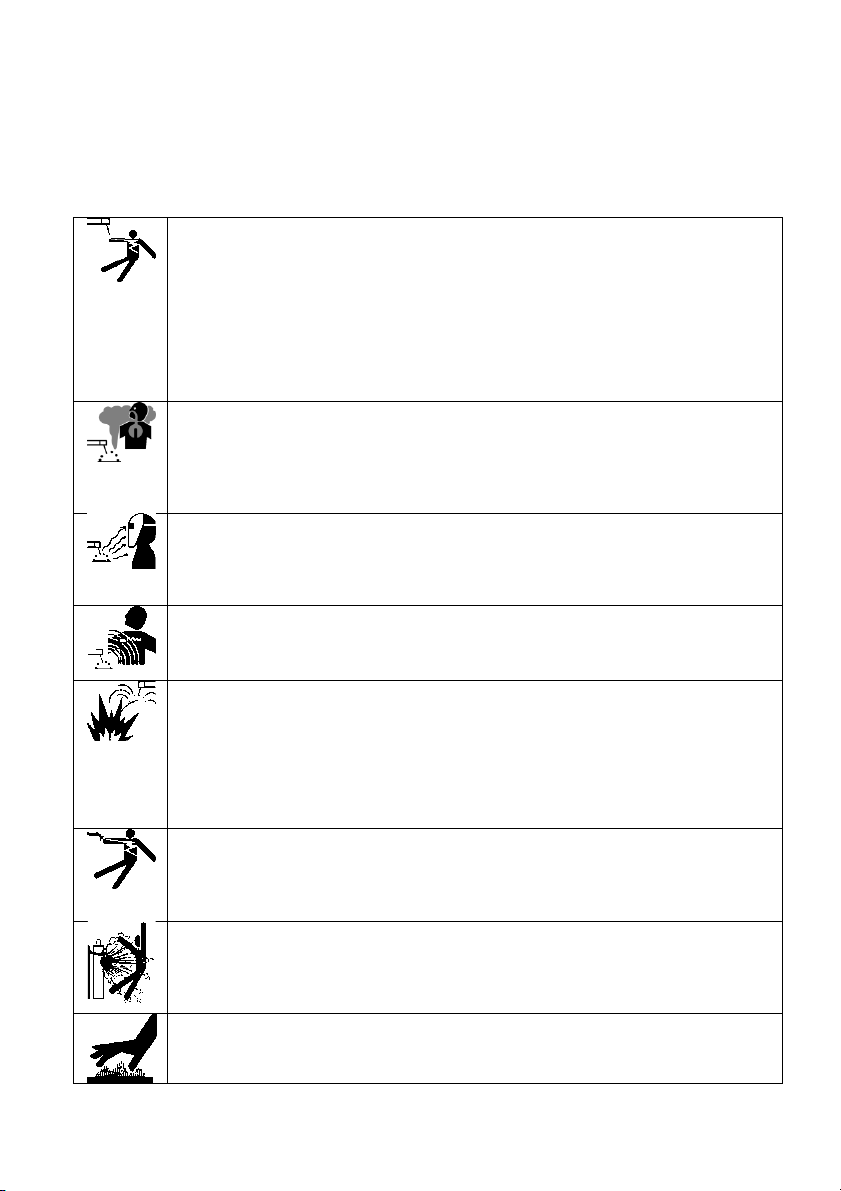
ELECTRIC SHOCK CAN KILL: Welding equipment produces high voltage. Do not touch the
welding gun or connected welding material when the device is plugged in. All components
forming the welding current circuit can cause electric shock, therefore it should be avoided to
touch them with bare hands or through damp or damaged protective clothing. Do not work on
wet surfaces or use damaged welding cables.
ATTENTION: Removal of external covers while the device is connected to the mains, as well
as operation of the device with removed covers is prohibited!
Welding cables, ground cable, earthing clamp and welding equipment should be kept in a good
technical condition ensuring safe operation.
FUMES AND GASES CAN BE DANGEROUS: The welding process produces harmful fumes and
gases that are hazardous to health. The workplace should be adequately ventilated and
equipped with a ventilation exhaust. Do not weld in closed rooms. Avoid inhaling vapors and
gases. The surfaces of the components to be welded should be free from chemical
contamination, such as degreasing substances (solvents), which decompose during welding,
producing toxic gases.
ARC RAYS CAN BURN: It is forbidden to look directly at the welding arc with unobstructed eyes.
Always use a mask or helmets with an appropriate filter. Protect the bystanders with the use of
non-flammable, radiation-absorbing screens. Protect the exposed parts of the body with suitable
protective clothing made of non-flammable material.
ELECTROMAGNETIC FIELD CAN BE DANGEROUS: The electric current flowing through the
welding cables creates an electromagnetic field around it. Electromagnetic fields can interfere
with pacemakers. Welding cables should be placed parallel, as close to each other as possible.
SPARKS CAN CAUSE A FIRE: Welding sparks can cause fire, explosion and burns to bare skin.
Wear welding gloves and protective clothing when welding. Remove or secure any flammable
materials and substances from the workplace. Do not weld closed containers or tanks containing
flammable liquids. Such containers or tanks should be rinsed before welding in order to remove
flammable liquids. Do not weld in the vicinity of flammable gases, vapors or liquids. Fire-fighting
equipment (fire blankets and powder or snow extinguishers) should be located near the
workplace in a visible and easily accessible place.
ELECTRICAL POWER: Disconnect the mains power before starting any work or repairs on the
device. Check welding cables regularly. If any damage to the wire or insulation is noticed, they
should be replaced immediately. Welding cables must not be crushed, touch sharp edges or hot
objects.
CYLINDER MAY EXPLODE: Use only approved cylinders and a properly functioning regulator. The
cylinder should be transported and stand in an upright position. Protect the cylinders against the action
of hot sources of heat, overturning and mechanical damage. Keep all components of the gas installation
in good condition: cylinder, hose, couplings, reducer.
WELDED MATERIALS CAN BURN: Never touch welded parts with unsecured body parts. Welding
gloves and tongs should always be used when touching and moving the workpiece.
8

5. EXPLANATION OF SYMBOLS
To reduce the possibility of injury, the user must read the entire
manual first.
A general warning sign draws the attention of each user to general
dangers. It is used in conjunction with other cautionary notes or
symbols that, if ignored, could result in personal injury or equipment
damage.
The product complies with the requirements of European Union directives.
With
For the disposal of electrical and electronic devices, see the DISPOSAL section in
this manual.
Use a welding shield or helmet.
Use welding gloves.
Wear protective welding shoes.
Use a welding cloth.
Secure the cylinder against falling over.
Electric shock hazard.
9

6. CONSTRUCTION AND CONTROL PANEL
1. Control panel.
2. Euro-socket for connecting the MIG-MAG work cable.
3. "PLUS" current output socket.
4. Cable with a plug to select the polarity - for MIG-MAG welding, it must be plugged into one of the sockets, according
to the selected polarity.
5. Spool Gun control socket.
6. "MINUS" current output sockets.
CAUTION:
The main power switch and a protective gas connection are located on the back of the device.
10

7. Knob for adjusting the wire feed speed for the MIG-MAG method. Adjustment
of the welding current value for the MMA and TIG Lift methods.
8. Welding voltage value control knob for the MIG-MAG method. For MMA method
- adjustment of the Arc force function.
9. Inductance adjustment knob for the MIG-MAG method.
10. Knob and button in one. It is used to select the welding method and other available parameters.
6.1 Device menu.
The knob-button 10 is used to enter the MENU of the device, confirm selections and exit
the MENU.
To enter the MENU, press the knob 10. The welding method selection screen will then be displayed.
11

Turn the knob 10 to select the desired welding method. Confirm the selection by
pressing the knob 10.
Looking from the left, you can choose from:
MIG SYN - MIG-MAG welding with the use of synergic programs.
MIG MAN - MIG-MAG welding with manual settings.
MMA - MMA welding.
TIG - welding with the TIG Lift
method. HELP - empty tab.
After selecting the welding method, the device displays a picture with a hint of a typical connection
of welding cables, e.g. for the MIG-MAG method:
To go further, press the MENU knob (10) again.
6.2 Synergic programs - MIG SYN.
After selecting a tab MIG SYN and going further behind the screen with a hint to attach the handles, the weld
material selection screen will appear:
By turning the MENU knob (10), select the required method and confirm by pressing the knob.
FE: ordinary steel.
SS: stainless and acid-resistant steel.
Al / Mg5, Al / Si: aluminum and its alloys.
FCAW-S: cored wires.
CuSi, CuAl: braze welding.
12

Another pressing of the MENU knob (10), depending on the previously selected welding method, is either a
screen with the shielding gas selection (program FE) or the wire diameter selection screen.
The next screen is a choice of 2T or 4T.
Pressing the MENU knob (10) again will bring you to the next screen - selection of the thickness of
the welded material.
Turning the MENU knob (10) set the thickness of the welded element.
Pressing the knob again confirms the set thickness and goes to the next screen - the screen
summarizing the previous selections.
13

Information about the selected welding method.
Detailed Summary Field:
WELDWAY: welding method.
MODE: 2T or 4T.
GAS: CO2 or MIX. The device does not
display the word Argon. In any case, it
replaces them with the word MIX.
MATERIAL: type of material to be welded.
DIAMETER: selected wire diameter.
THICKNESS: set thickness of
the welded material.
Numerical and graphic information
about the set welding wire feed speed.
In the case of welding with the use of
synergic programs, depending on the
previously set parameters, the device
14

will set the optimal wire feed speed.
The device allows you to correct this speed and change it in full range, even if it is set
incorrectly. The correct numerical value for the wire feed speed is displayed in white.
The graphic slider will also be in the white area. When the wire feed speed is set outside
the optimal range, the numerical value turns red and the graphic slider turns
it will be on the red field.
Correction of the welding voltage is the same
as above. A full range of adjustments are
available. Numerical value
displayed in white and the slider in the white field
are optimal values.
A slider in the red field and a digital
value in red indicate settings outside
the optimal range.
The lower right corner is a numerical and
graphical representation of the set
inductance value. As with the wire feed
speed and voltage settings, the correct
value is white and an incorrect value is red.
Summary of synergic programs:
Program Shielding gas Wire diameter Material thickness range
MIX (Ar + CO2)
CO2 or MIX (Ar + CO2)
0.6 mm
0.8 mm
1.0 mm
0.7 ÷ 3.4 mm
0.8 ÷ 4.8 mm
1.0 ÷ 6.4 mm
FE (plain steel)
SS (stainless and
acid-resistant steel) 100% Argon or
Ar + 2% CO2
0.8 mm
1.0 mm
0.9 ÷ 4.8 mm
1.0 ÷ 6.4 mm
AlMg5, AlSi5 (alloys
aluminum) 100% Argon
MIX *
100% Argon
1.0 mm
1.2 mm
0.9 ÷ 4.8 mm
1.2 ÷ 6.4 mm
FCAW-S (wires
spinal)
0.8 mm
1.0 mm
0.8 mm
1.0 mm
0.8 ÷ 4.8 mm
1.0 ÷ 6.4 mm
0.8 ÷ 4.8 mm
1.0 ÷ 6.4 mm
CuSi, CuAl
(braze welding)
MIX * - in the case of self-shielding cored wires, there is no need to use shielding gas. In the case of
non-self-shielding cored wires, the appropriate shielding gas specified by the manufacturer should
be used.
15

6.3 Manual MIG-MAG settings
When selecting the MIG-MAG method with manual settings (MIG MAN) the device does not impose or
enforce any settings (except for selecting 2T or 4T).
The user can set the wire feed speed, voltage and inductance in the full and any
range.
6.4 Wire burnout and Spool Gun.
There is a knob inside the feeder
chamber Burn back and a switch
Spool Gun / Wire feeder.
Knob Burn back is used to adjust the
burnback height of the wire after
welding is finished. With this
knob, you can adjust the
distance from the contact tip to
the welding wire.
The Spool Gun switch is used to enable
this function. When the switch is in the
Spool Gun position - the machine's
wire feeder does not work.
16

The Spool gun holder is an optional welding holder (sold separately), characterized by a
considerable length - usually 5 to 10 meters - and a wire spool feeder with a diameter of 100
mm, mounted on the handle.
To weld with such a holder:
- connect the ground cable to the material to be welded,
- coil or remove the welding wire from the device feeder chamber,
- set the switch on the device to the Spool Gun position,
- connect the control plug and the current plug of the Spool Gun to the corresponding sockets on the front panel of the
device.
Due to the fact that there are many types and varieties of SPOOL GUN handles on the market, which may
differ in parameters, it is necessary to check and possibly synchronize with the device before connecting it.
Such synchronization can only be performed by an authorized service of the manufacturer / importer of the device.
6.5 MMA settings.
To weld with the MMA method, select this welding method in the MENU.
Then, after going through the screen that prompts you to connect the welding cables, select the type of
electrodes used.
Designation 60XX denotes rutile electrodes (e.g. E 6012, E 6013), and 70XX stands for basic electrodes
(eg E 7018).
The next screen is to select the diameter of the electrode used:
17

Although the device offers a choice of only the most commonly used electrode diameters (from 2.5 mm to 4.0
mm), later you can use smaller diameters (e.g. 1.6 mm, 2.0 mm), because the device does not limit
the welding current adjustment range.
After selecting the electrode diameter, the thickness of the welded material should be set:
When all the above parameters have been set, the device "shakes" into the specified value and
characteristics of the welding current. Everything will be summarized on the final screen:
The knob on the left side can - if necessary - set the welding current, and the knob on the right side
set the Arc Force value.
Despite the synergy used in the MMA method and adjusting the parameters based on
previous selections, the device in no way limits the full range of adjustments that can be
made at any time during welding work.
6.6 TIG Lift settings
To weld with the TIG Lift method, select this welding method in the
MENU. Then the device will suggest how to connect the welding cables.
On the next screen, select the diameter of the tungsten electrode to be used. You can choose a diameter of 1.6 or
2.4 mm. Of course, other electrode diameters can be used, because despite the selections made, the device does
not limit the range of welding current regulation.
18

7. USE
7.1 Connecting to the network
Before attaching this mains equipment must be checked for size
voltage, number of phases and frequency.
The parameters of the supply voltage are given in the technical data section of this manual and on
the rating plate of the device.
Check the connections of the equipment grounding conductors to the mains.
Make sure that the mains power supply can cover the input power demand of this
device under normal operating conditions.
The fuse size and power cord parameters are given in the technical data of this
manual.
The supply network should be characterized by a stable voltage. The cross-section of the
power cables should not be less than 2.5 mm.
Connect devices without power plugs according to the instructions below.
Connection and replacement of the power cord and plug should be performed by
a qualified electrician.
The yellow-green wire is the ground and should always be connected to the socket marked
with the grounding symbol, regardless of whether we are dealing with a 230 [V] or 400 [V]
power supply.
Earth electrode symbol (PE).
7.2 Installation of welding cables - MIG / MAG.
ATTENTION! Pull the plug out of the socket before carrying out
any work on the device.
1. Make sure the device is not connected to the mains.
2. Check that the ground cable is terminated with a clamp or screw clamp.
3. Connect the mass cable plug to the output socket on the front panel with appropriate
polarity, press and turn. A too loose connection of the plug causes premature burnout
of the plug and the socket. Mass cable in the MIG-MAG method
19

we usually connect to the "-" socket, in the case of using the self-shielding wire to the
"+" socket (contrary to the hint displayed on the screen of the device).
The second, empty output socket is plugged into the plug hanging on the built-in cable. This
is necessary to close the welding current circuit. Without a plug plugged into one of the
output sockets (plus or minus), the device will not weld!
4. Before installing the welding cable, make sure that there is an appropriate armor leading to
the appropriate diameter and grade of the electrode wire. To make things easier,
manufacturers of guiding armor mark them with appropriate colors. For wire diameter
0.6 ÷ 0.8 mm, it is blue, for a wire with a diameter of 1.0 ÷ 1.2 mm, it is red, and
for an electrode wire with a diameter of 1.6 mm, it is yellow. We use Teflon armor
for welding alloy steels and aluminum. Metal spiral armor is used for welding low
carbon steel, low alloy steel, copper, bronze etc. Remember to equip the welding
torch with a contact tip appropriate to the type and diameter of the electrode
wire.
5. Plug of the welding cable "Euro-plug" insert into the socket (euro socket) on the front
panel of the welding machine, then tighten the nut by hand until it stops.
7.3 Loading the Electrode Wire.
1. Make sure that the rollers installed in the drive unit correspond to the type and
diameter of the introduced wire. If the roll groove differs from the diameter of
the electrode wire, adjust the groove by turning it over or replacing the roll. For
steel wires, use rolls with V-grooves, and for aluminum wires with U-grooves.
2. Put the spool with the wire electrode on the spool mounting mechanism, making sure that the
wire unwinding direction is consistent with the direction the wire enters the drive unit. The
special construction of the spool body allows the use of wires on standard spools with an internal
diameter of 53 mm, as well as small spools with an internal diameter of 17
mm.
3. Lock the spool against falling by tightening the nut on the spool body.
4. The end of the wire wound on the spool, straighten or cut off the bent section, then file it
down so that it is not sharp.
5. To enable the introduction of the wire into the feeder, release the pressure of the feed rolls.
6. Insert the end of the wire into the guide at the rear of the feeder and guide it
over the drive rolls and insert it into the socket leading to the welding holder.
20
This manual suits for next models
1
Table of contents
Other Magnum Welding System manuals

Magnum
Magnum MIG 208 Alu Synergy User manual

Magnum
Magnum MIG 208 Alu Synergy User manual

Magnum
Magnum CARIMIG 202LCD User manual

Magnum
Magnum MIG 160 Mini User manual

Magnum
Magnum MIG 208 ALU SYNERGIC User manual

Magnum
Magnum MIG200L PRO DUAL PULSE User manual

Magnum
Magnum 100SG SPOOL GUN User manual

Magnum
Magnum WAVE 200KD User manual

Magnum
Magnum MIG 190 II DIGITAL User manual