Magnum MIG 208 Alu Synergy User manual

INVERTER OPERATING MANUAL
SEMI-AUTOMATIC WELDING
Model:
MIG 208 Alu Synergy
The drawings of the device in the manual may differ in colors from the original.
Translation of the original instructions.
with
ATTENTION: Please use the welding machine after reading the manual very carefully.
1. To ensure safe operation, select qualified personnel responsible for the
installation, maintenance, periodic inspection, and repair of this equipment.
2. In order to ensure safety, before working with the device, carefully and fully
understand the following operating instructions.
3. After reading the following instruction manual, place it in a place accessible to
other users of the device.
1

2

Table of Contents
1.
2.
3.
4.
5.
INTENDED USE ............................................. 4
TECHNICAL DATA................................................ .......................... 5
RULES FOR SAFE USE ......................................... 5
EXPLANATION OF SYMBOLS ................................................ .................... 9
CONSTRUCTION AND CONTROL PANEL .............................................. ...... 10
5.1 Synergic programs and settings. .................................................. ....12
5.2 Advanced settings ............................................... ................... 14
6. CONTENTS OF THE SET .............................................. ................... 15
7. USE ............................................... ............................... 15
7.1 Connecting to the network .............................................. ............................. 15
7.2 Assembling the welding cables - MIG / MAG ................................. 16
7.3 Loading the Electrode Wire .............................................. ............. 16
7.4 Connecting the shielding gas. .................................................. ..........17
7.5 Selection of welding parameters for MIG / MAG .......................................... . 17
7.6 Practical recommendations for MIG / MAG welding. .........................18
8.
9.
10.
11.
12.
13.
CLEANING AND MAINTENANCE ............................................... ...... twenty
INTERFERENCE IN THE WELDING MACHINE (DEVICE ERROR CODES) 21
STORAGE AND TRANSPORT ............................................. 22
DISPOSAL ................................................. .............................. 22
DECLARATION OF CONFORMITY ................................................ ......... 23
WARRANTY. .................................................. ...........................23
3

1. INTENDED USE
MIG 208 Alu Synergy by MAGNUM is a technologically advanced welding device
for MIG-MAG, MMA, TIG LIFT, FCAW and Brazing methods. Designed for manual,
electric welding of low-carbon and low-alloy steels, low and high-alloy steels,
aluminum and its alloys, copper and its alloys, braze welding, etc.
MIG 208 Alu Synergia is intended for all kinds of welding works in locksmith
workshops, repair shops, automotive industry, factories, etc. The device is
dedicated to professionals who require meeting the highest standards for
welding equipment.
The power source was built on transistors IGBT ensuring minimum electromagnetic
interference, low power losses in basic systems, enabling increased efficiency and
reliability of the power source. Very high efficiency, which translates directly into
lower energy consumption, and high switching frequency ensure instant
adjustment of the current to changes in parameters during welding.
The MIG 208 Alu Synergia device has, among other advantages, a synergistic program for
welding aluminum alloys, unique in this class of devices.
The design and software allow for the highest quality welds when welding all
weldable materials, made of carbon steel, stainless steel, copper and
aluminum alloys.
The manufacturer is not liable for damages resulting from use
contrary to the intended use.
4

2. TECHNICAL DATA
MODEL MIG 208 Alu Synergy
Power
Protection required. Welding
current MIG / MAG
Welding voltage MIG / MAG
AC 230 [V], 50/60 [Hz]
20 [A]
20 ÷ 180 [A]
15 ÷ 23 [V]
78 [V]
0.6 / 0.8 / 0.9 / 1.0 / 1.2 [mm]
40%
IP21S
16 [kg]
Idle voltage
Wire diameter *
(* see program table)
Efficiency
Housing protection class
Weight
Dtechnical information is subject to change without notice.
3. RULES FOR SAFE USE
Read all and all safety regulations
instructions.Failure to follow the health and safety regulations and instructions may
result in electric shock, fire and / or serious injury.
Save all safety regulations and instructions for future reference.
Keep children away from the working area of the device. People
with a pacemaker should consult their physician before using the
device. Service and repair of the device
may be carried out by qualified personnel in compliance with the work safety
conditions applicable to electrical devices.
Modifications on their own may change the functional features of the device or
deteriorate welding parameters. Any modifications to the device, on their own,
not only void the warranty, but may also deteriorate the safety conditions of
use and expose the user to the risk of electric shock. Improper working
conditions and improper operation may damage the device and void the
warranty.
5

OHS MANUAL
in electric welding
3.1. General thoughts.
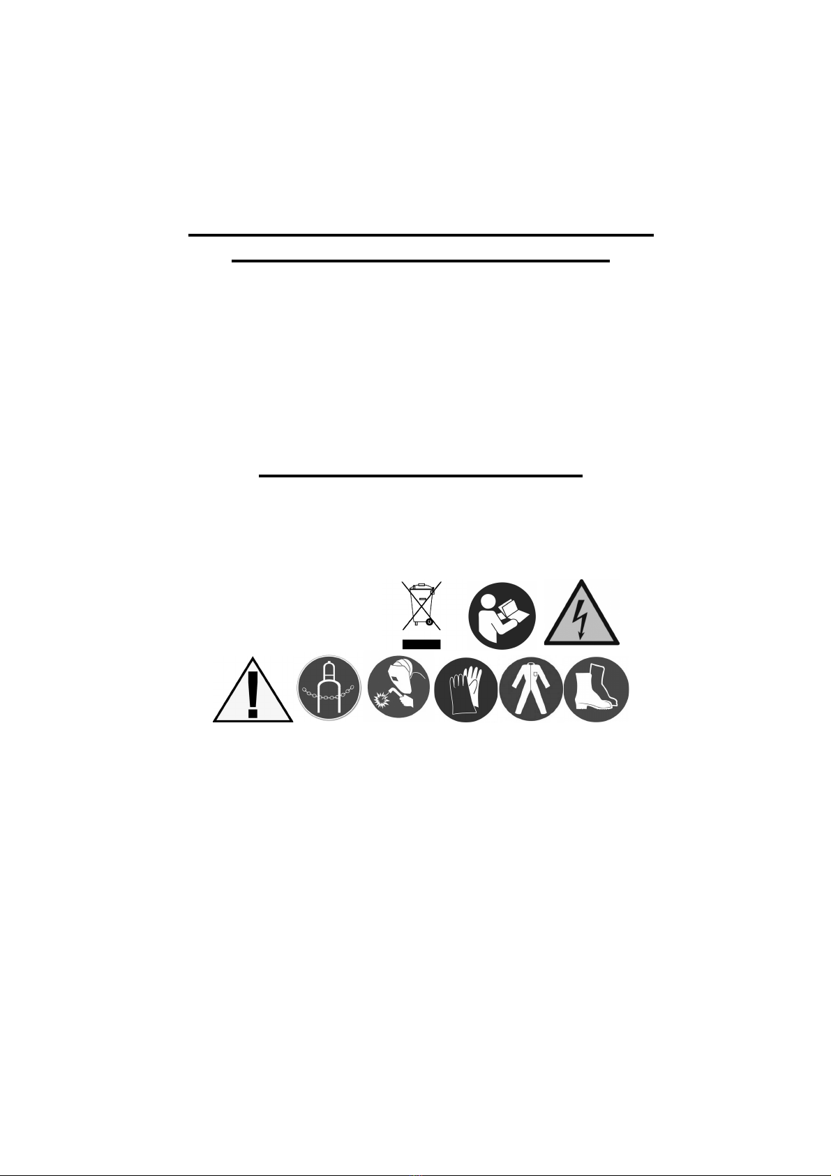
a) You should commence work rested, sober, wearing work clothes made of
flame-retardant fabric or leather, cover your hair with a beret or a cap, wear
shoes with flame-retardant trousers, welding gloves and personal protection, a
leather apron, welding mask, protective glasses, individual respiratory protection
equipment.
b) Work related to the installation, disassembly, repair and inspection of electric welding
devices should be performed by employees with appropriate qualifications.
c) The connection of several welding energy sources should not result in exceeding, in the no-
load condition, the permissible voltage between the output circuits of the connected energy
sources.
d) The welding current circuit should not be earthed, except when the items to
be welded are connected to earth.
e) Welding cables connecting the workpiece with the energy source should be
connected directly to the workpiece or tooling, as close to the welding site as
possible.
3.2. Basic activities before starting work.
The welder should:
a) read the executive documentation and the scope of welding works,
b) plan the sequence of performing individual welds,
c) prepare an appropriate binder,
d) prepare adequate face and eye protection,
e) check the condition of the connections of the welding installation and the working handle,
f) check that the welding process does not pose a threat to the environment (arc radiation,
possibility of ignition of easily ignitable elements),
g) check if there is no ignition on the other side when welding on the wall,
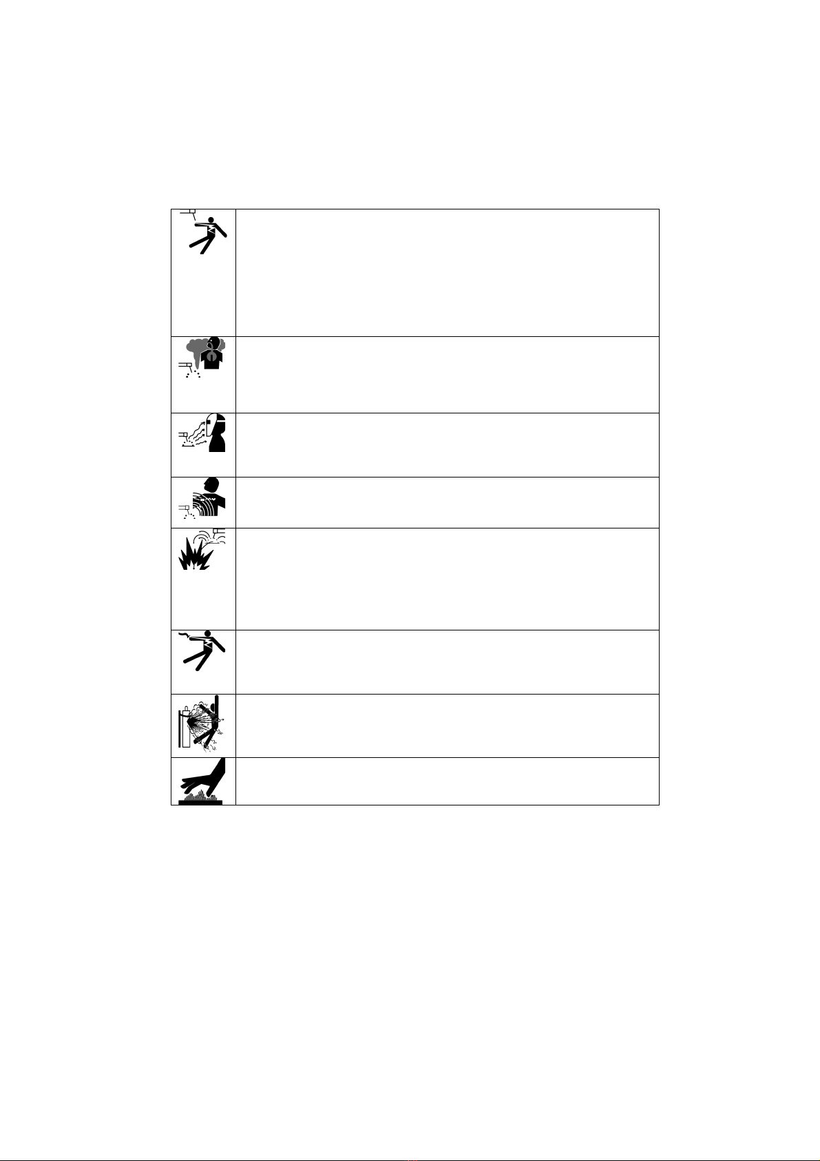
3.3. Activities during welding.
a) Secure the workplace, unless there are fixed, movable anti-
glare and anti-spatter screens.
b) For welding electric wires and a work handle, use only those in good technical
condition (undamaged insulation).
c) Only use the correct thickness of electrodes and wires for welding.
d) Fasten and set up the welded object reliably and solidly and so that it will not be
damaged.
e) Position the workpieces to be welded in such a way as to prevent their shifting or
tipping over. Use needle hammers and protective glasses when deflecting slag.
f) When welding inside boilers, tanks or in confined spaces, regardless of the
ventilation used, use respiratory protection.
g) When working inside tanks, boilers and other metal rooms, use 24V
electric lighting.
h) Make sure that the welded element does not cause a risk of falling or moving away dangerous for the
welder.
6

and)
j)
use of appropriate personal protection.
k) Turn on the individual air extraction, if one is installed, so that the gaseous fumes are removed
from the station.
l) Use only correct, undamaged and free of oil tools and aids
workshop.
3.4. Prohibited activities.
A welder is prohibited from:
a) Gripping hot metal that is ready for welding or after welding.
b) Repair damaged electric cables (electrical system) yourself.
c) During breaks in work, keep the electrode holder under the armpit.
d) Moving the welding mask too far away from the face, putting it down before the arc goes out,
and igniting the arc without face protection.
e) Welding without proper grounding of the workpiece.
f) Use a makeshift combination of welding equipment.
g) Cause the floor at the workplace to be wet, slippery, uneven,
contaminated with rubbish, obstructed.
3.5. Basic post-work activities.
The welder should:
a) Disconnect the welding machine from voltage.
b) Check that no fire has occurred during welding at or next to the stand.
c) Tidy up the workplace, remove the electrode tips and welding slag.
d) Organize the welding equipment.
3.6. Final remarks.
a) When welding works inside tanks, boilers or other closed rooms (up to 15
m3), the welder should be insured by another person outside.
When welding on scaffolding, check the condition of their efficiency.
Protect respiratory system, eyes, face and hands from burns and exposure to light
7

ELECTRIC SHOCK CAN KILL: Welding equipment produces high voltage. Do not touch the
welding gun or connected welding material when the device is plugged in. All components
forming the welding current circuit can cause electric shock, therefore it should be avoided to
touch them with bare hands or through damp or damaged protective clothing. Do not work on
wet surfaces or use damaged welding cables.
ATTENTION: Removal of external covers while the device is connected to the mains, as well
as operation of the device with removed covers is prohibited!
Welding cables, ground cable, earthing clamp and welding equipment should be kept in a good
technical condition ensuring safe operation.
FUMES AND GASES CAN BE DANGEROUS: The welding process produces harmful fumes and
gases that are hazardous to health. The workplace should be adequately ventilated and
equipped with a ventilation exhaust. Do not weld in closed rooms. Avoid inhaling vapors and
gases. The surfaces of the components to be welded should be free from chemical
contamination, such as degreasing substances (solvents), which decompose during welding,
producing toxic gases.
ARC RAYS CAN BURN: It is forbidden to look directly at the welding arc with unobstructed eyes.
Always use a mask or helmets with an appropriate filter. Protect the bystanders with the use of
non-flammable, radiation-absorbing screens. Protect the exposed parts of the body with suitable
protective clothing made of non-flammable material.
ELECTROMAGNETIC FIELD CAN BE DANGEROUS: The electric current flowing through the
welding cables creates an electromagnetic field around it. Electromagnetic fields can interfere
with pacemakers. Welding cables should be placed parallel, as close to each other as possible.
SPARKS CAN CAUSE A FIRE: Welding sparks can cause fire, explosion and burns to bare skin.
Wear welding gloves and protective clothing when welding. Remove or secure any flammable
materials and substances from the workplace. Do not weld closed containers or tanks containing
flammable liquids. Such containers or tanks should be rinsed before welding in order to remove
flammable liquids. Do not weld in the vicinity of flammable gases, vapors or liquids. Fire-fighting
equipment (fire blankets and powder or snow extinguishers) should be located near the
workplace in a visible and easily accessible place.
ELECTRICAL POWER: Disconnect the mains power before starting any work or repairs on the
device. Check welding cables regularly. If any damage to the wire or insulation is noticed, they
should be replaced immediately. Welding cables must not be crushed, touch sharp edges or hot
objects.
CYLINDER MAY EXPLODE: Use only approved cylinders and a properly functioning regulator.
The cylinder should be transported and stand upright. Protect the cylinders against the action of
hot sources of heat, overturning and mechanical damage. Keep all components of the gas
installation in good condition: cylinder, hose, couplings, reducer.
WELDED MATERIALS CAN BURN: Never touch welded parts with unsecured body parts. Welding
gloves and tongs should always be used when touching and moving the workpiece.
8

4. EXPLANATION OF THE SYMBOLS
To reduce the possibility of injury, the user must read the entire
manual first.
A general warning sign draws the attention of each user to general
dangers. It is used in conjunction with other cautionary notes or
symbols that, if ignored, could result in personal injury or equipment
damage.
with The product complies with the requirements of European Union directives.
Disposal of electrical and electronic devices - see section DISPOSAL in
this manual.
Use a welding shield or helmet.
Use welding gloves.
Wear protective welding shoes.
Use a welding cloth.
Secure the cylinder against falling over.
Electric shock hazard.
9

5. CONSTRUCTION AND CONTROL PANEL
Method 3 sec.
smyignm
blinkan-tig-mma -
1
mm
AND +
MIG 208 Alu
Synergy
-
V+
Choice
Material-about-gas
point-2t / 4t
3 sec.
2 -
3
4 +
5
1. Control panel.
2. Current output socket "minus".
3. Euro socket.
4. Current output "plus" socket.
5. Cable for polarity reversal.
NOTE: WHEN MIG-MAG WELDING THE CABLE MUST BE INSERTED IN ONE OF THE
OUTPUT OUTLETS.
6. Near the polarity reversal cable - SPOOLGUN gun control socket.
The main switch and the protective gas connection are located on the rear of the device.
1. Display.
2. Knob / multifunction button.
3. Knob / multifunction button.
2
3
1
10

Pressing the knob for 2 seconds or longer and releasing it causes
entering the menu where you can choose the welding method.
The selection is made by turning the knob in any direction.
The selected symbol will then flash. Confirm your selection
by briefly pressing the knob.
SON - MIG-MAG welding with synergic
settings.
MAN - MIG-MAG welding with manual
settings (traditional).
MMA welding
Welding with the TIG LIFT method.
When selecting the MMA or TIG LIFT method, only the welding current value remains
to be set by turning the upper knob.
If the MIG-MAG method with manual settings is selected, the upper knob is adjusted
wire feed speed, the value of the welding
voltage with the lower knob. The set value will
be shown on the display.
The value of the welding current will be shown only
during welding.
Being in manual mode MAN you can also choose
spot welding and the behavior of the control
button, i.e. 2t or 4t.
To select one of the
above, press
not shorter than 2 seconds the lower knob until the following symbols
appear. The spot welding symbol will flash.
By turning the lower knob
this function is turned on / off and the welding
time at point is set.
Adjustment range: OFF, 0.1 ÷ 5.0 [s].
At the moment of selecting spot welding and setting the
welding time at the point, it is not possible to select 4t.
11

If spot welding is set to off, press the lower
knob briefly.
The symbol will flash together with the selected 2t or 4t
option.
The selection is made by turning the lower knob.
Confirmation takes place by another short press of the
lower knob.
If the welder is on 4t, the display during operation
shows the symbol in both manual mode
and synergistic.
If 2t is on, the display does not show
the above symbol.
5.1 Synergic programs and settings.
After confirming the choice of synergic mode, the display shows the current program and other parameters:
- type of material selected,
- wire diameter,
- shielding gas,
- ATC (if material thickness ≤1.5 mm)
- material thickness,
- wire feed speed,
- graphical indicator of the shape of the weld and material thickness,
- welding voltage and current (during welding),
- on 4t.
To enter the menu that allows you to select the type of material, wire diameter and shielding gas, press the lower
knob for at least 2 seconds until the following symbols appear. One of the symbols in the group
materials will flash. By turning the lower knob in
any direction, select the symbol of the required
material (it should flash). Confirm the selection by
briefly pressing the lower knob. Only the symbol of
the selected material will be displayed (the others
will disappear), and one of the available wire
diameters (in the diameter group) will start
flashing. Similarly as before, by turning the lower
knob in any direction, set the required wire
diameter.
Confirm the diameter and move to the
group of shielding gases by briefly pressing
the lower knob.
Then select the required shielding gas with the lower knob by turning it in any direction. A short
press of the lower knob confirms the selection and exits the menu.
After leaving the synergic mode menu, the welder should be adjusted depending on the thickness of the
welded element - it is used by the upper knob.
12

When this knob is turned to the right or left, the display will change the numerical value of the wire feed
speed, the material thickness in millimeters, and the graphic thickening or thinning of the material:
Depending on the material thickness selected, the ATC symbol will also appear.
ATC is an advanced thermal control function that is active when welding thin materials up to
1.5mm thick.
The ATC function stabilizes the electric arc and reduces the peak value of the welding current, reducing the
amount of heat transferred to the material. As a result, it significantly facilitates the welding of thin elements
and results in less deformation of the material, less overheating and a narrow heat-affected zone.
In turn, the lower knob is used to adjust the shape of the weld (arc length) in the range -9 ÷ 9.
The graphic symbol of the weld shape will change on the display:
Convex shape means low heat load with poor fusion into the material. Intermediate shape
is the recommended setting, with moderate penetration into the material.
The concave shape means a high thermal load with high fusion into the material.
LIST OF SYNERGY PROGRAMS
Material Wire diameter [mm] Shielding gas
Fe - normal steels 0.6 / 0.8 / 1.0 WHAT2 / Ar + CO2
Ss - stainless and acid-resistant steels 0.8 / 1.0 Ar + O2 / Ar + CO2 (1-2%)
Al - aluminum and aluminum alloys
CuSi, CuAl - braze welding
Flux - welding with cored wires
0.8 / 1.0
0.8 / 1.0
0.8 / 0.9 / 1.2
Ar
Ar
Ar *
Ar * - use the gas recommended by the wire manufacturer.
In the case of self-shielding wire, the use of shielding gas is not required.
13

5.2 Advanced Settings.
The MIG 208 Alu Synergia device has the ability to adjust additional, advanced parameters for the
MIG-MAG method, both in synergic and manual mode.
Wire starting speed (approaching). Regulation in the range of 30 ÷ 100 [%] of the feeder's
rotational speed.
Inductance regulation. Adjustment in the range of 0 ÷ 5.
Higher inductance (soft arc) results in a wider weld pool and less spatter.
Conversely, the lower inductance produces a stable, focused arc.
Burn back height after welding. Adjustment in the
range of 0 ÷ 200 [ms].
Gas flow time after completion of welding.
Adjustment in the range of 0 ÷ 5 [s].
To enter the menu that allows you to adjust the above parameters,
press and hold both adjustment knobs simultaneously for at least 2
seconds.
Adjustment is done by turning the lower knob.
Moving to the next parameter, confirming and exiting the
menu by briefly pressing the lower knob.
14

6. KIT CONTENTS
The following items should be included in the kit:
Welding device
MIG / MAG work cable
MMA work cable
Cable with ground clamp
Feed roller kit.
x 1 pcs
x 1 pcs
x 1 pcs
x 1 pcs
Attention!
For the safety of children, do not leave freely accessible parts of the
packaging (plastic bags, cartons, polystyrene, etc.).
Danger of suffocation!
7. USE
7.1 Connecting to the network
Before attaching this mains equipment must be checked for size
voltage, number of phases and frequency.
The parameters of the supply voltage are given in the technical data section of this manual and on
the rating plate of the device.
Check the connections of the equipment grounding conductors to the mains.
Make sure that the mains power supply can cover the input power demand of this
device under normal operating conditions.
The fuse size and power cord parameters are given in the technical data of this
manual.
The supply network should be characterized by a stable voltage. The cross-section of the
power cables should not be less than 2.5 mm.
Connect devices without power plugs according to the following tips.
Connection and replacement of the power cord and plug should be performed by
a qualified electrician.
The yellow-green wire is the ground and should always be connected to the socket marked
with the grounding symbol, regardless of whether we are dealing with a 230 [V] or 400 [V]
power supply.
Earth symbol.
15

7.2 Installation of welding cables - MIG / MAG.
ATTENTION! Pull the plug out of the socket before carrying out
any work on the device.
1. Make sure the device is not connected to the mains.
2. Check that the ground cable is terminated with a clamp or screw clamp.
3. Connect the mass cable plug to the output socket on the front panel with appropriate
polarity, press and turn. A too loose connection of the plug causes premature burnout
of the plug and the socket. The mass cable in the MIG-MAG method is usually
connected to the "-" socket, in the case of using a self-shielding wire to the "+" socket.
The second, empty output socket is plugged into the plug hanging on the built-in cable. This
is necessary to close the welding current circuit. Without a plug plugged into one of the
output sockets (plus or minus), the device will not weld!
4. Before installing the welding cable, make sure that there is an appropriate armor
leading to the appropriate diameter and grade of the electrode wire. For ease of use,
manufacturers of guiding armor mark them with appropriate colors. For wire diameter
0.6 ÷ 0.8 mm, it is blue, for a wire with a diameter of 1.0 ÷ 1.2 mm, it is red, and
for an electrode wire with a diameter of 1.6 mm, it is yellow. We use Teflon armor
for welding alloy steels and aluminum. Metal spiral armor is used for welding low
carbon steel, low alloy steel, copper, bronze etc. Remember to equip the welding
torch with a contact tip appropriate to the type and diameter of the electrode
wire.
5. Plug of the welding cable "euro-plug" insert into the socket (euro socket) on the front
panel of the welding machine, then tighten the nut by hand until it stops.
7.3 Loading the Electrode Wire.
1. Make sure that the rollers installed in the drive unit correspond to the type and
diameter of the introduced wire. If the roll groove differs from the diameter of
the electrode wire, adjust the groove by turning it over or replacing the roll. For
steel wires, use rolls with V-grooves, and for aluminum wires with U-grooves.
2. Put the spool with the wire electrode on the spool mounting mechanism, making sure that the
wire unwinding direction is consistent with the direction the wire enters the drive unit.
3. Lock the spool against falling by tightening the nut on the spool body.
4. The end of the wire wound on the spool, straighten or cut off the bent section, then file it
down so that it is not sharp.
5. To enable the introduction of the wire into the feeder, release the pressure of the feed rolls.
6. Insert the end of the wire into the guide at the rear of the feeder and guide it
over the drive rolls and insert it into the socket leading to the welding holder.
16

7. Press the wire into the grooves of the drive rolls by tightening the
clamp.
8. Remove the gas nozzle and unscrew the contact tip.
9. Turn on the device.
10. Unfold the handle so that it is in a straight line, then press
the button on the handle until the wire appears in the
outlet (approx. 20 mm), release the button.
11. Screw on the contact tip, install the gas nozzle.
12. Adjust the pressure force of the feed roller by turning
the pressure knob. Contact pressure too low, cause
drive roller will slip. Too high pressure force increases the feeding resistance
and deforms the wire, which may result in cutting it.
7.4 Connecting the shielding gas.
1. The cylinder with the appropriate shielding gas should be placed on the shelf of the semi-
automatic machine (if any) or against a wall and secure it against tipping over by securing it to the
bracket with a chain.
2. Remove the cap protecting it and unscrew the cylinder valve for a moment to
remove any contamination.
3. Install the regulator so that the gauges are in a vertical position.
4. Connect the semi-automatic machine with the cylinder (outlet from the reducer with the welding machine's stub)
with a suitable hose. The protective gas connection is located on the back of the device.
5. Unscrew the reducer valve only before welding. After welding is finished, the cylinder
valve should be closed.
6. Avoid welding in an open space or in a draft - a blast of air can
disrupt the shielding gas stream and strip the liquid metal of its protection.
7.5 Selection of welding parameters for MIG / MAG
The basic parameters of the MIG / MAG welding process are: welding
current and electrode wire feed speed. Increasing the welding current causes an
increase in penetration (penetration depth) and elongation of the arc. Increasing
the wire feed speed causes the handle to be pushed upward from the workpieces.
This is because the welding current is too low. When the wire feed speed is too slow
or the welding current is too high, large droplets form at the end of the wire
electrode. Too large spattering indicates that the welding current is too low or the
electrode wire feed speed is too high. When welding in wall and ceiling positions,
the welding current can be reduced, while making filler welds, in order to obtain a
smooth face, the welding current can be increased.
17

7.6 Practical recommendations for MIG / MAG welding.
Butt welds in the flat position should be performed using the "push"
technique for thin elements and the "pull" technique for thicker elements. Butt
welds in the vertical position for thin elements should be made from top to
bottom. Fillet welds in the side position should be made using the "push"
technique, but taking into account the additional inclination of the welding
torch in the plane perpendicular to the direction of welding. When filling wide
grooves in a flat or vertical position, make transverse swinging movements
with the end of the handle. During welding, the welding torch should be at the
right angle to the welded elements - too large an angle of inclination may
cause air to be sucked into the molten metal pool (the angle of the torch
deflection from the vertical should be ≤ 10 °).
Welding with a short arc (at the same current density) increases the penetration depth - the
weld is narrower and the material spatter becomes smaller. Welding speed is a result
parameter for a given current and arc voltage and maintaining the correct shape of the weld
bead and when the welding speed is to be changed even slightly, the current or arc voltage
should be changed accordingly. The increase in welding speed causes the weld to be narrower
and the fusion depth decreases, and with further growth, the face undercut appears. The
highest welding speeds without undercutting can be achieved by increasing the free electrode
outlet and tilting the workpiece from top to bottom or tilting the torch in the direction of
welding. Low welding speeds increase the fusion depth, the width of the face and the height
of the riser.
Excessive elongation or shortening of the arc
can cause unstable arc glow and poor weld
quality.
L1, L2 - arc length
The direction of welding also has a significant
impact on the penetration depth - the welding
torch guidance.
H1, H2 - penetration depth
Due to the type of shielding gas used and electrical parameters
of the welding process (voltage and current), there are three ways to change the state
of metal in the welding arc:
18

THICK-DROP - used in the MIG / MAG method at low
current densities and a long arc
- not recommended in forced positions
SPRAY - used in the MAG method with gas
mixtures
- not recommended in forced positions
SHORT-CIRCUIT - used in the MAG method with a short arc
- recommended for welding elements of
small thickness and in forced positions
The protective gas determines the efficiency of the welding area shield, but also the method of
metal transfer in the arc, the welding speed and the shape of the weld. The inert gases argon and
helium, while perfectly protecting the liquid weld metal from the atmosphere, are not suitable for all
MIG-MAG welding applications. By mixing helium or argon in appropriate proportions with
chemically active gases, a change in the nature of metal transfer in the arc is achieved, the stability
of the arc increases and the possibility of influencing the metallurgical processes in the weld pool
appears. At the same time, it is possible to significantly reduce or completely
elimination of spatter.
Protective gas Chemical action Welded metals
Ar inert Essentially all metals except carbon steels
Al, Cu, Cu alloys, Mg alloys, high linear energy of welding is
ensured
He inert
Al, Cu, Cu and Mg alloys, high linear energies of welding
ensured, low thermal conductivity of gas
Ar + 20-80% He inert
Copper welding with high linear energy of the arc, better arc glow
than in the 100% N shield2
Mainly recommended for welding corrosion-resistant and
alloy steels
Ar + 25-20% N2reducing
Ar + 1-2% O2weakly oxidizing
Ar + 3-5% O2oxidizing Recommended for welding carbon and low-alloy steels
WHAT2oxidizing Recommended only for welding low carbon steels
Recommended only for welding carbon and low-
alloy steels
Ar + 20-50% CO2oxidizing
Recommended only for welding carbon and low-
alloy steels
Ar + 10% CO2+5% O2oxidizing
Recommended only for welding low carbon and low
alloy steels
WHAT2+20% O2oxidizing
19

90% He + 7.5% Ar +
2.5% CO2
e + 35% Ar + 5%
WHAT2
weakly oxidizing Corrosion-resistant steels, short-arc welding
60% of H. High toughness low alloy steels, short arc
welding
oxidizing
8. CLEANING AND MAINTENANCE
The protection class of this device is IP21S, so do not use the device in the rain or
expose it to moisture.
CAUTION:
Device based on electronic components. Grinding and cutting
metals near the welding machine can contaminate the inside of the
device with filings, thus damaging it.
The above-mentioned damage is not subject to warranty repair!
If you need to work in such an environment, clean the device by
blowing the inside of the welder with compressed air.
In order to extend the service life and reliable operation of the device, several rules must be followed:
1. The device should be placed in a well-ventilated room with free air circulation.
2. Do not place the device on wet ground.
3. Use wire of the diameter and weight of the spool in accordance with the table.
4. Place the shielding gas cylinder on the shelf at the back of the semi-automatic machine and
secure it against the possibility of tipping over with a chain.
5. Check the technical condition of the device and welding cables.
6. Remove any flammable materials from the welding area.
7. Use appropriate protective clothing for welding: gloves, apron, work shoes, mask
or visor.
When planning the maintenance of the device, the intensity and conditions of use should be taken into
account. Correct use of the device and regular maintenance will help to avoid unnecessary disturbances
and breaks in work.
Every day:
ABOUTClean the mass handle and gas nozzle from spatter, lubricate with anti-
spatter agents.
ABOUTCheck that the cables are securely connected.
ABOUTCheck the condition of the wires. Replace damaged cables.
ABOUTMake sure that there is free air flow around the device.
ABOUTReplace or repair damaged or worn parts.
twenty
Other manuals for MIG 208 Alu Synergy
1
Table of contents
Other Magnum Welding System manuals

Magnum
Magnum 100SG SPOOL GUN User manual

Magnum
Magnum MIG 190 II DIGITAL User manual

Magnum
Magnum MIG200L PRO DUAL PULSE User manual

Magnum
Magnum MIG 208 Alu Synergy User manual

Magnum
Magnum WAVE 200KD User manual

Magnum
Magnum CARIMIG 202LCD User manual

Magnum
Magnum MIG 208 ALU SYNERGIC User manual

Magnum
Magnum MIG 160 Mini User manual

Magnum
Magnum MIG 220 Alu synergy User manual