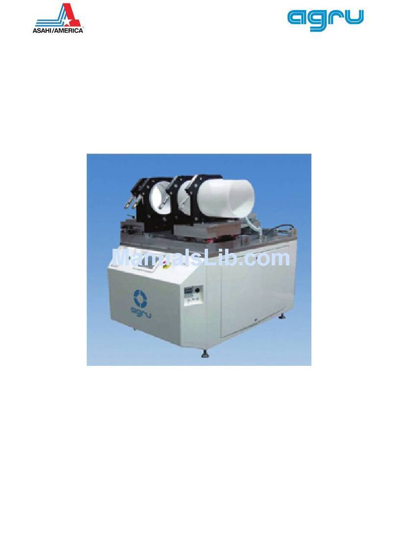
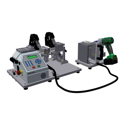
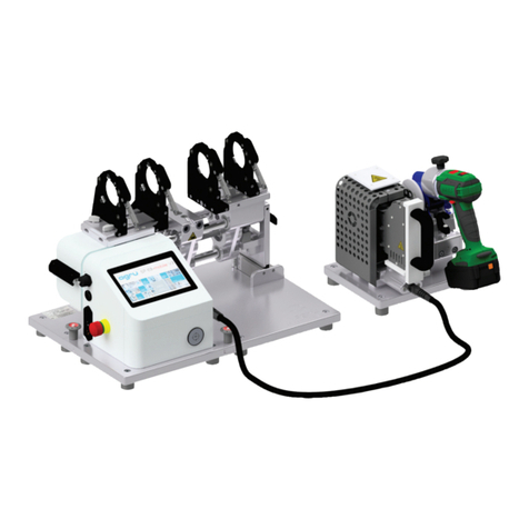
AGRU EF 110-B User manual

User’s Manual
Mobile Welding System for Inside Beadless Welding
EF 110-B
Version October 2015
P.O. Box 1108 • 655 Andover St.,Lawrence, MA 01843 • Tel: (800) 343-3618, (781) 321-5409

Version October 2015 EN 3
agru EF 110-B User’s Manual
Contents
1 Introduction ...........................................................................................................5
2 Safety Messages ...................................................................................................5
2.1 Reading the User's Manual ...................................................................................5
2.2 Explaining Icons ....................................................................................................5
2.3 Safety Messages and Information on Remaining Risk .........................................6
2.4 User/Operator Obligations ....................................................................................7
2.5 Worksite Description .............................................................................................7
2.6 Warranty ................................................................................................................7
2.7 Transport and Storage ..........................................................................................8
2.8 Identifying the Machine .........................................................................................9
3 Product Description and Principles of Operation ..................................................9
3.1 Intended Use .........................................................................................................9
3.2 Machine Description ..............................................................................................9
3.2.1 Component Overview ............................................................................................9
3.2.2 Control Panel ......................................................................................................10
3.2.3 Ports and Switches .............................................................................................10
3.2.4 Specifications ......................................................................................................11
3.3 Welding Process Overview .................................................................................11
4 Operation ............................................................................................................12
4.1 Check-out, Turning on, Selecting the Display Language ....................................12
4.2 Entering Traceability Data for the Joint ...............................................................14
4.3 Entering or Changing the Job Number and Joint Number ..................................14
4.4 Configuring the Welding System .........................................................................15
4.5 Entering Welding Parameters Manually ..............................................................16
4.5.1 Manually Entering Welding Voltage and Time .....................................................16
4.5.2 Entering the String of Numbers ...........................................................................17
4.6 Performing the Welding Process .........................................................................17
4.6.1 Facing the Component Ends before Welding......................................................17
4.6.1 Connecting the Electrofusion Fitting ...................................................................18
4.6.2 Reading the Fitting Code with a Scanning Pen or Handheld Scanner ................18
4.6.4 Direct Welding with the AutoWeld Feature ..........................................................19
4.6.5 Inserting the Components and the Balloon at the Start of the Welding Process 19
4.6.6 Welding Process .................................................................................................20
4.6.7 End of Welding ....................................................................................................20
4.6.8 Cooling Time .......................................................................................................20
4.7 Aborted Welding Process ....................................................................................21
4.8 Using ViewWeld to View Welding Reports and Print Tags ..................................22
5 Downloading the Reports ....................................................................................23
5.1 Selecting the File Format ....................................................................................23
5.2 Downloading All Reports .....................................................................................23
5.3 Downloading by Commission Number, Date or Report Range ...........................23
5.4 Understanding the Report Download Process ....................................................23
5.5 Deleting Data from Memory ................................................................................24
5.6 Keeping Data in Memory .....................................................................................24
6 System Data ........................................................................................................24
6.1 Displaying Characteristics of the Welding Unit ....................................................24
6.2 Measuring Resistance .........................................................................................24
6.3 Overheating Switch .............................................................................................24
6.4 Indication of Power Supply Failure at the Last Welding ......................................25
7 Service and Repair ..............................................................................................25
8 Service and Repair Contact ................................................................................25
8.1 Manufacturer Warranty ........................................................................................25
8.2 Technical Documentation ....................................................................................25
8.3 Risk Assessment .................................................................................................25
8.4 Included in Standard Delivery .............................................................................26
Declaration of Conformity ................................................................................................27

Version October 2015
4EN agru EF 110-B User’s Manual
Caution
The machine has to be operated exclusively with
a power supply line equipped with a protective
grounding conductor, as a power supply without
this safety element may cause severe machine
damage. If the machine is operated through a
power supply without a grounding conductor,
this will void any and all warranty under which
the product may be.

Version October 2015 EN 5
agru EF 110-B User’s Manual
1 Introduction
Dear Customer:
Thank you very much for purchasing our product. We are confident that
it will meet your expectations.
The development, manufacture, and check of the mobile, i. e., overhead-
welding-enabled, electrofusion welding system for inside beadless plastic
pipe jointing has been guided by our concern to offer a unit character-
ized by superior operation safety and user-friendliness. The unit was
manufactured and checked according to the most recent standards as
they are applied, and bearing ergonomic aspects in mind.
To ensure maximum operation safety, please conform to the appropriate
messages in this booklet and the regulations for the prevention of acci-
dents. Carefully read the User’s Manual to avoid damage to the machine
or hardware in its environment as well as injury.
This manual is applicable to the following system:
agru EF 110–B
Thank you.
2 Safety Messages
This User’s Manual contains important instructions for operating the
mobile plastic welding system for inside beadless welding agru EF 110–B
safely. Every person who operates the system will have to conform to
the instructions of this manual.
The machine has been developed and checked with respect to welding
AGRU pipes and fittings. For welding other makes, no experiential data
are available and/or no liability or warranty can be assumed for the fit-
ness and the reliable operation of the machine.
2.1 Reading the User's Manual
The User’s Manual is presented according to sections which explain the
different functions of the product.
All rights, in particular the right to copy or reproduce (in print or electronic
form) and distribute as well as to translate, are reserved and subject to
prior written consent.
2.2 Explaining Icons
The following expressions and icons are used in this User’s Manual to
refer to safety-related issues:
Caution
This icon indicates that non-compliance may result in a haz-
ardous situation that possibly causes bodily injury or material
damage.
Important
This icon indicates important messages related to the correct
use of the machine. Non-compliance may cause problems of
operation and damage to the machine.
Info
This icon indicates tips and useful information for using the
machine more efficiently and more economically.

Version October 2015
6EN agru EF 110-B User’s Manual
2.3 Safety Messages and Information on Remaining Risk
Protect the power supply cord from cutting edges. Have an authorized
service shop replace damaged cables or lines immediately.
The machine has to be operated with a 230 V, 50/60 Hz power supply with
safety fuse or breaker of 16 A maximum. If power is connected through
a power line manifold, the power supply has to feature an earth-leakage
circuit breaker.
Use only extension cables with the following conductor sections:
– max. length of cable 25 m (80 ft) min. section 2.5 mm²
– max. length of cable 50 m (160 ft) min. section 4.0 mm²
Caution
Parts Under Power
After opening the machine or removing the cover, parts of it
are accessible that may be under power. The machine may be
opened exclusively by an authorized service shop.
Caution
Facing Tool
Never switch the facing tool on when it is not in its regular
working position. When working with the facing tool, do not
wear any jewellery and put on a hair snood or net as needed.
Removing the shavings from the work area while the facing
tool is running, is prohibited. Make sure nobody is present in
the danger zone.
Caution
Electrofusion Fitting
A welding process must never be repeated with the same fit-
ting, since this may cause parts under power to be accessible
to the touch.
Caution
Checking the Product for Damage
Before every use of the product, check safety features and
possibly existing parts with minor damage for proper function.
Make sure that the push-on connection terminals work properly,
that contact is fully established, and that the contact surfaces
are clean. All parts have to be installed correctly and properly
conform to all conditions in order for the product to function as
intended. Damaged safety features or functional parts should be
properly repaired or replaced by an approved service shop.
Caution
Acceptable Work Conditions
The work zone has to be clean and has to have proper lighting.
It is dangerous to operate in a humid environment or close to
flammable liquids.
The electrofusion fitting manufacturer’s installation instructions
and all applicable rules and regulations have to be respected in
all cases. Acceptable work conditions have to be ensured (e.g.,
sufficient distance between the machine and other functional
areas of the workshop).
Overhead work is prohibited, unless:-
• the machine is safely and securely fastened and positioned;
•access to a large area around the worksite is controlled/limited
•(risk of falling objects); see also Sect. 2.5;
• a hardhat and safety goggles are worn (risk of falling objects and
•small blades of shaving during component facing)
Important
Power Supply Only through Line with Protective Grounding
Conductor
The system has to be operated exclusively with a power supply
line equipped with a protective grounding conductor, as a power

Version October 2015 EN 7
agru EF 110-B User’s Manual
supply without this safety element may cause severe damage.
If the system is operated through a power supply without
a grounding conductor, this will void any and all warranty
under which the product may be.
Important
Competent Use of the System
Use the appropriate connection terminal that is compatible with
the electrofusion fitting type used. Be sure the contact is firmly
established and do not use connection terminals or terminal
adapters that are burnt or not designed for the intended use.
Do not carry the product by its cables and do not pull the power
cord to unplug the unit from the socket. Protect the cables
against heat, oil, and cutting edges.
Important
No Foreign Bodies in Work Area
The system must never be used if there are foreign bodies or
objects that might interfere with the process in the work area; in
particular, it must not be started if anything could compromise
or damage the welding cable.
Info
User’s Manual
The User’s Manual has to be available at any time on the site
where the machine is used. If the User’s Manual should come
to be incomplete or illegible replace it without delay. Feel free
to contact us for assistance.
2.4 User/Operator Obligations
• The system may be operated exclusively by persons who are fa-
miliar with the applicable rules, the guidelines for the prevention of
accidents, and the User’s Manual.
• The system may be operated only when observed. Only persons who
were properly trained by agru or another, authorized organization
and whose training was acknowledged by an appropriate certificate
are allowed to operate and observe the system. Other persons must
neither operate nor observe it.
•The operating/owning organization engages to check at reasonable
intervals if the system is operated by the users with the intended
use and under proper guidelines of safe work.
• The user has to make sure that only one person is present in the
zone where the system is operating.
• The system must be in proper state of repair when it is put into
service. Prior to starting the system, the user is required to verify
that the system is safe and in proper state of repair.
2.5 Worksite Description
• The conditions have to fully ensure that the system cannot slide.
In case of overhead welding operations, the mechanical structure
has to be securely fastened at the components to be jointed with
the supplied belts.
• Worksite access limitations have to be provided. Appropriate equip-
ment to achieve this can be requested from a service point or the
selling entity.
2.6 Warranty
Warranty claims may be raised only if the conditions for warranty given
in the General Terms and Conditions of Sale and Shipment obtain.One
precondition is that proper maintenance according to the required sched-
ule (see Sect. 7) is ensured.

Version October 2015
8EN agru EF 110-B User’s Manual
Info
The term of warranty under which the welding machine is
shipped is 12 months:-
— from the date of purchase, if the machine is bought as a new
— machine;
— from the date of first use, if it is used independently of
— purchase (e.g. when lent) or not bought as a new machine.
2.7 Transport and Storage
During transport, the machine must be at all times in the transport box
it is shipped in.
Important
During transport, the movable parts have to be secured with the
transport lock at all times (see guidelines and figures below).
The transport box should also be used to store the machine. The machine
has to be stored in a dry location, be clean or has to be cleaned, and be
locked against unwanted operation.
Important
When the printer is moved or shipped, the roll of labels in the
printer has to be removed.
Inside view of the case for the
reducer inserts
!!
Remove battery from power tool during transport
!!
!!
Remove label roll during transport
!!
Fitting Clamps
Mechanical Structure
Battery for Facing Tool
Power Facing Tool
Charger for Facing Tool Battery
Star Knobs Serving as Transport Lock
Case for Reducer Inserts
Box for Welding Cable, Air
Hoses for Cooler and
Balloon, Accessories, etc.
Balloon Tray
Label Tag Printer
Control Unit
User's Manual
Second Battery for Facing Tool

Wulstlos-Elektroschweißsystem
Typ agru EF 110-B
Geräte-Nr. 11015801
Netz 230V 50Hz 2000VA 80% ED
Gewicht 21kg Baujahr: 2015
Lizenzhersteller
HÜRNER Schweißtechnik GmbH
Nieder-Ohmener Str. 26
D - 32325 Mücke
Typ agru EF 110-B
Exklusives Produkt der Fa.
agru Kunststofftechnik GmbH
Ing.-Pesendorfer-Str. 31
A - 4540 Bad Hall
Tel. +43 7258 7900
Fax +43 7258 3863
Version October 2015 EN 9
agru EF 110-B User’s Manual
2.8 Identifying the Machine
Each machine is identified by a name plate. It shows the machine model
(“Typ”), its year of manufacture (“Baujahr”), the serial number (“Geräte-
Nr.”), the rated power (“Netz”), and the manufacturer (“Lizenzherstel-
ler”).
3 Product Description and Principles of Operation
3.1 Intended Use
The mobile welding system for inside beadless welding agru EF 110–B
is intended exclusively for joining plastic pipes and fittings according to
the electrofusion process, i. e. electrical-thermoplastic jointing with a
heater coil fitting (also called an electrofusion fitting). See Sect. 3.3 for
an overview of the welding process enabled by this system.
Only the welding parameters encoded in the fitting-specific bar code
can be used for a welding operation. When jointing with agru’s specialty
fittings for inside beadless welding, RFID transponder cards are used
instead of the bar code as the means of data input. If welding parameters
are entered manually, conform to the fitting manufacturer’s instructions.
Any modification of the control software or the welding parameters it
contains is strictly prohibited.
It is also part of the intended use to conform to the instructions provided
in the User’s Manual.
Important
The manufacturer can in no circumstances be held liable for
damage or consequential damage that occurs as a result of the
non-compliance with the procedures described in the User’s
Manual, the failure to use relevant welding parameters, or the
non-intended use. Any such deviation will void any and all war-
ranties under which the product may be.
3.2 Machine Description
3.2.1 Component Overview
Facing Tool
Control Unit
Fitting Clamp/Facing Tool
Carriage
Pipe/Component Clamps
Fitting Clamps ø 20 - 63 mm

Version October 2015
10 EN agru EF 110-B User’s Manual
3.2.2 Control Panel
3.2.3 Ports and Switches
The machine can be used as an in-shop or worksite system and with
anodized aluminum components, it is also suited for clean room applica-
tions. The machine enables users to enter the data that are relevant for
the welding process and for the traceability of the welded joint. From the
entered welding parameters, it calculates the applicable welding time
and controls the welding process automatically.
All welding and traceability data are entered with the keypad on the
front panel or read from a code card using RFID radio identification.
Alphanumeric Keypad
MENU and Cursor Keys
Buzzer
Welding Cable Connector
START/SET and STOP/
RESET Keys
Display Screen
Tilting Handle
Balloon Support
On/Off Switch
Balloon Connector
USB Interface Port
Cooling Air Connector
Compressed Air Supply
Connector
Air Pressure Regulator
Air Pressure Gauge
RFID Transponder
Reader
Power Supply Connector for
Label Tag Printer (covered by
dust cap)
Power Socket 230 V AC

Version October 2015 EN 11
agru EF 110-B User’s Manual
The welding process in monitored in its entirety and saved to a welding
report. All welding reports can then be downloaded to a USB stick as
an abstract or extended report in the PDF format or in the DataWork
database management format.
Using the menus, the machine can be customized to the application at
hand (see Sect. 4.3, Configuring the Machine).
3.2.4 Specifications
agru EF 110-B
Power Supply Characteristics
Voltage
Frequency
Rated Power
Input Current
Max. Output Current
Output Voltag
230 V AC
50 / 60 Hz
2000 VA, 80% duty cy.
approx. 10 A
approx. 40 A
8 V - 48 V
Welding Operation Specs
Ambient Temperature (operation)
Ambient Temperature (storage)
Operating Range
Ingress Protection
Welding Report Memory Capacity
USB Communication Interface
– 10°C to + 45°C (+ 14°F to 113°F)
– 25°C to + 65°C (– 13°F to 149°F)
max. component size 110 mm
IP 54
10,000 reports
USB v 2.0 (480 mbit/s)
Dimensions and Weight
Dimensions (W x D x H)
Mechanical Structure
Control Unit
Transport Box
Weight
Mechanical Structure
Control Unit
Facing Tool
Transport Box with All Elements
Empty Transport Box
675 x 200 x 190 mm
420 x 320 x 240 mm
800 x 600 x 608 mm
approx. 6 kg
approx. 15 kg
approx. 4 kg
approx. 83 kg
approx. 42 kg
3.3 Welding Process Overview
The welding system allows welding electrofusion fittings that feature a
bar code. Every e-fitting is provided with a tag with one or two bar codes
on it. The structure of this code is internationally standardized. The first
code, encoding the data on proper welding, complies with ISO 13950,
the second code, if present, encoding the component traceability data,
complies with ISO 12176. The welding parameters can also be entered
manually.
When using an inside balloon in the pipe, beadless welding is possible.
To automate a beadless welding process, a special code with 34 digits,
which builds on the abovementioned 24-digit code^s, has to be read from
a RFID transponder card or entered manually. The parameters related
to balloon pressure can also be entered manually.
The welding system is microprocessor-controlled and:-
• controls and monitors the welding process in a fully automated way,
when the welder starts it after component preparation,
• determines welding duration depending on ambient temperature,
• shows all information on the display in plain text.
The welding process is performed as follows:
• All welding parameters and traceability data for the components
are read from a RFID transponder card or a bar code or entered

Version October 2015
12 EN agru EF 110-B User’s Manual
manually on the front panel keypad (as and when requested on the
screen by the system).
• The reducer inserts are set into the clamps of the mechanical struc-
ture of the system.
• The facing tool is set onto its carriage, and the component ends
are faced.
• The outcome of facing is checked and, if o.k., the facing tool is
replaced with the fitting clamp and the electrofusion fitting, set into
it.
• The contact terminals of the welding cable are connected to the con-
nectors of the the electrofusion fitting; push-on adapters appropriate
for the fitting are added to the terminals previously if needed.
• Using the spacer bar for reference, first one component is inserted
into the fitting, then the spacer bar, removed and the second com-
ponent is inserted into the fitting.
•If a beadless joint is desired, the inside balloon is positioned before
the second component is inserted into the fitting; when inserting
the balloon, it has to be clean.
• When the correct position of the balloon is confirmed on the screen,
the system fills it with compressed air, asks on the screen if all
preparatory steps are done, and, when the answer is affirmative,
performs the welding operation automatically through to the cooling
stage.
• Only at the end of the cooling stage, the connection between the
welding system and the electrofusion fitting may be disconected.
If this happens earlier, the welded joint is deemed incorrect and of
poor quality. If the operation was a beadless welding, the system
keeps the balloon inflated to the end of the cooling stage, and the
user will have to release the air before the next jointing job.
4 Operation
Before putting the machine into operation, review the transport locks and
safety auxiliaries as well as the way the machine is set into its transport
box. Whenever the machine is moved or shipped, it has to be set into
this box and secured for transport (see Sect. 2.7 for reference).
Important
When the printer is moved or shipped, the roll of labels in the
printer has to be removed
Info
When installing the reducer inserts, place the narrower inserts
into the inner clamps, the broader inserts, into the outer clamps.
The insertion and the removal of the inserts is performed with-
out any tools. The reducers are secured to the clamps by the
force of the magnets only.
4.1 Check-out, Turning on, Selecting the Display Language
Place the machine, in particular the mechanical structure with the pipe
clamps, on a level surface and ensure it cannot slide. Sufficient distance
has to be kept to other areas, especially to those in which flammable
materials are used. When starting the machine up, remove all transport
locks (see Sect. 2.7) if they are locked, before applying power to the
system. Furthermore, if the label tag printer ist planned to be used later
on, connect it to the machine and insert the roll of labels before the first
welding operation.
Depending on the piece that is going to be welded, the outer clamps
may have to be repositioned or removed. To do so, loosen the locking
thumb screws and either remove the clamp or re-adjust it and secure it
by tightening the locking screws again.

Version October 2015 EN 13
agru EF 110-B User’s Manual
If the diameter of the pieces to be welded is smaller than the clamp, insert
the reducer inserts. This can be done without using any tools since the
inserts are fastened in the clamps by magnetic attraction.
Important
Pipe clamps and reducer inserts have to be clean or must be
cleaned before welding starts. To insert or remove the inserts,
do not use heavy tools (hammer, wrench). They may damage
the inserts and the magnets.
Important
If power supply to the welding system is by a generator, read
carefully and respect the manual that comes with the generator.
Furthermore bear the following in mind:
The required nominal generator capacity as determined by the
power supply requirement of the largest electrofusion fitting
to be welded depends on the power supply specifications, the
environment conditions, and the generator type itself including
its control/regulation characteristics.
Nominal output power of a generator 1-phase, 220 - 240 V, 50/60 H z :
d 20 ...... d 110 3.2 kW
Start the generator first, then connect the welding unit. The idle
voltage should be set to approx. 240 volts. When turning the
generator off, disconnect the welding unit first.
The working output power of the generator decreases by about
10% per 1,000 m of altitude. During the welding process no
other device connected to the same generator should be oper-
ated.
Caution
Overhead work is prohibited, unless:-
• the machine is safely and securely fastened and positioned;
• access to a large area around the worksite is controlled/limited
•(risk of falling objects); see also Sect. 2.5;
• a hardhat and safety goggles are worn (risk of falling objects and
•small blades of shaving during component facing)
Important
Make sure all connectors are tight in their sockets and make
sure that the machine is operated only if the conditions for safe
and intended use are met (see also section 2). Safety on the
power supply side will be ensured by a 16 A slow blow fuse.
An earth-leakage/residual current breaker is required when the
system is used on construction sites.
Important
If the label tag printer is going to be used with the machine,
it, too, has to be fully connected and switched on before the
machine is turned on. Failure to do so may result in loss of data
and damage to the machine. First connect the power suppy from
the machine to the label tag printer, then switch the printer on,
and finally connect the USB data cable to the appropriate ports
of the machine and the printer, then only switch the welding
system on.
After preparing the machine for welding and connecting its power supply
cord to the mains supply, the machine is turned on using the On/Off switch.
The welcome screen reproduced in Display 1 appears on the screen.
The machine then takes the user to the welder code input screen if welder
code input is enabled in the configuration menu.
If the machine finds that something is wrong or that the last joint was not
properly welded (power supply failure, clock failure, etc.; see Sect. 4.7),
Display 1
********************
AGRU
AGRU EF 110-B
********************

Version October 2015
14 EN agru EF 110-B User’s Manual
Display 5
* Commission Number*
********************
************
an error message is displayed instead of the welder code input screen.
Then, the error has first to be cleared.
Read the welder identification code by holding a transponder card in front
of the RFID reader. Alternatively reading it from a bar code or typing it on
the front panel and saving it by pressing START/SET is also possible.
Info
All inputs for which a data card is available can be entered by
having the RFID reader read that card.
Info
The alphanumeric keypad is designed and works like the keypad
of a common mobile phone without touch screen display. All
characters found on a key can be “browsed” by pressing that
key repeatedly at short intervals. As soon as “browsing” gen-
erates the desired character on the screen, wait a little longer
until you press the next key to use the displayed character. The
first character always is the number on the respective key, then
the letters or marks in the order on the key, i. e., for instance,
with the key “2 | a | b | c” the 1st keypress brings up “2,” the 2nd
“a,” the 3rd “b,” and the 4th brings up “c.” By default, lower-case
letters appear on the screen. To enter upper-case letters, hold
down the × key while selecting the appropriate letter by one
or several keypresses.
4.2 Entering Traceability Data for the Joint
After the welder identification code was entered, the traceability data
for the joint have to be entered.All traceability data enabled in the con-
figuration menu at “Data Recording” (see Sect. 4.4) have to be entered
before the welding process. The welding unit prompts the user to enter
them either before or after entering the e-fitting bar code (see Display 3).
Depending on what data is entered, either its repeated input is manda-
tory (e. g., the welder ID code; see Sect. 4.1) or previously entered data
can be changed and confirmed or confirmed without changes (e. g. the
commission number; see Sect. 4.3).
Certain traceability data can also be accessed quickly, via a selection
screen, by pressing the Õ cursor key (see Display 4), either for viewing
or for entering or changing/confirming them (for the AutoWeld feature
mentioned along with them on this screen, see Sect. 4.6.4).
When the traceability data were entered, the machine displays the bar
code input screen again (see Display 3). In this display, the no-contact
message on the last line disappears when the contact from the welding
system to the electrofusion fitting has been established.
4.3 Entering or Changing the Job Number and Joint Number
Entering these two traceability data is explained as an illustration for all
these data, the input of which is performed in the same manner. Only
the weather conditions are selected in a list using the ×,Ø cursor keys,
and the selection is then confirmed by the START/SET key.
The commission number input screen is shown by the unit before welding
or accessed by the user in the quick access screen (Display 4). It can
be entered using the alphanumeric keypad (see last Info in Sect. 4.1) or
by reading it from a bar code using the scanning pen or scanner or from
an RFID card using the reader. The maximum length is 32 characters.
Confirm your input by pressing the START/SET key. The job number will
be saved to memory and will appear in the printed welding report.
Provided is was enabled in the configuration menu (see Sect. 4.4), a
commission number-related joint number is also recorded and saved to
Display 2
Enter Welder Code
********************
****************
Display 3
Enter Fitting Code
10.10.14 08:24:58
Supply 229V 50Hz
No Contact
***** Recording ****
AutoWeld
>Welder Code
Commission No.
Display 4

Version October 2015 EN 15
agru EF 110-B User’s Manual
the report. To say that the joint number is related to the job, or commis-
sion, number means that the system checks, when a commission number
was entered, whether it exists already in the internal memory. If so, it
takes the highest existing joint number for that commission, increments
it by 1, and applies this new joint number to the next welding operation
in that commission.
4.4 Configuring the Welding System
In Display 3, the welder has the possibility to:
• read the welding parameters from a bar code or a RFID card and
start a welding process (move on to Section 4.6);
• enter the welding parameters for the next welding manually and
start the welding process (move on to Section 4.5);
• change the sytems settings in the configuration menu (press the
MENU key).
Accessing the menu requires an access code (see Display 6). The menu
is structured according to three submenus, the third of which, “Sensor
Parameters,” does not contain any parameters important for welding, but
only for set-up and maintenance work. They are therefore protected by a
second access code that is disclosed only to authorized personnel. The
configuration menu has the items listed in the following table.
To toggle from « On » to « Off » or vice versa for an option, press the
Öcursor key, to open a submenu or go to an additional screen for an
option, which is indicated by the letter – M –, press the MENU key.
Designation Setting Description / Data to be entered
—— “Settings” submenu ————————
AutoWeld ON / OFF "on” means that for two subsequent welding with identical welding/
fitting parameters, the parameters of the preceding one are applied
automatically to the following one (see Sect. 4.6.4), “off,” that the
parameters have to be read or entered again for every new wleding
operation.
Check Code Expiry ON / OFF "on” means that the welder identification code has to be current and
not expired (default period of validity 2 years from code issuance),
or the welding operation cannot be started, “off,” that the validity of
the code is not checked at all.
Memory Control ON / OFF if ON: Machine stops when the memory is full;
if OFF: Machine overwrites the oldest report when the memory is
full.
Manual Input On / Off "on” means that the manual input of welding parameters or
computed parameters is possible, “off,” that the manual input is not
allowed.
Welder Code Options Menu In a sub-menu, it can be determined when the welder code, if it is
enabled at “Recording,” has to be entered: always, i. e. before evey
single welding operation, only before the first welding operation after
switching the unit on or only after the first welding operation of a
new day/date..
Language Menu In a sub-menu, the language in which display texts and reports are
edited can be selected.
Date/Time Menu In a sub-menu, date and time can be set.
Buzzer Volume Menu In a sub-menu, the volume of the audible signal that the machine
emits to validate the execution of a given step in the process can be
set.
Temperature Unit
(°C / °F)
Menu In a sub-menu, the temperature unit used for displaying and saving
welding data can be selected.
Unit of Pressure
(bar / psi)
Menu In a sub-menu, the unit of pressure used for displaying and saving
welding data can be selected.
Display 6
Enter Menu Code
******

Version October 2015
16 EN agru EF 110-B User’s Manual
Designation Setting Description / Data to be entered
Invetory Number Menu In a sub-menu, the number under which the unit is inventorized with
the operating company can be entered.
Number of Tags Menu In a sub-menu, the number of tags to be printed with respect to a
welded joint can be selected.
—— “Recording” submenu ————————
Welder Code ON / OFF “on” means that the welder identification code has to be entered as
set with “Welder Code Options,” “off,” that this is impossible.
Commission Number ON / OFF “on” means that the commission number (job number) will have to be
entered or confirmed before every new welding, “off” that the user is
not prompted to enter it.
Joint Number ON / OFF “on” means that the unit assigns an automatically incremented joint
number to every welding operation belonging to a commission
already known, and displays this number on the screen next to the
report number, “off” that no joint numbers will be assigned at all.
Additional Data ON / OFF “on” means that the additional data will have to be entered or
confirmed before every new welding, “off” that the user is not
prompted to enter them.
Fitting Code ON / OFF “on” means that the second, so-called traceability code of the
electrofusion fitting has to be entered before every welding, “off,”
that this is not possible.
Pipe Codes ON / OFF “on” means that the codes of both pipes/components (ISO-compliant
welding and treaceability codes) have to be entered before every
welding, “off,” that this is not possible.
Pipe Length ON / OFF “on” means that the length of both pipes/components has to be
entered before every welding, “off,” that this is not possible.
Weather Conditions ON / OFF “on” means that the weather has to be selected in a list before every
welding, “off,” that this is not possible.
Installing Company ON / OFF “on” means that the company that performs the installation work has
to be entered before every welding, “off,” that this is not possible.
Print Tags Menu means that by pressing the MENU key, the user can access a sub-
menu for starting to print (a) label(s) with reference to a given
welding operation, with the optional label tag printer.
4.5 Entering Welding Parameters Manually
To be able to enter the welding parameters manually, you have first to
connect the electrofusion fitting to the welding unit with the welding cable.
The manual input of the parameters can then be accessed by pressing
the Ø arrow key. The screen will show a menu as reproduced in Dis-
play 7, provided manual input is enabled in the configuration menu (see
Sect. 4.4). In other words, the manual parameter input replaces reading
the bar code of the fitting with a scanning pen or scanner or reading a
RFID transponder card (see Sect. 4.6).
Using the arrow keys × and Ø you can select “Enter Voltage/Time” or
“Enter Fitting Code” (i.e., the numbers that represents the code of the
fitting to be used). Confirm your selection by pressing the START/SET
key.
4.5.1 Manually Entering Welding Voltage and Time
If this option was chosen in the manual parameter input menu, a display
like the one to the right appears on the screen. Use the alphanumeric
keypad (see last Info in Sect. 4.1) to set the welding voltage (V) and the
welding time (T1), according to the fitting manufacturer’s instructions,
then press the START/SET key to confirm your input. The “Start ?” mes-
sage displayed after the confirmation by START/SET (see Display 10)
indicates that the unit is ready for welding.
Display 7
** MANUAL INPUT **
>Enter Voltage/Time
Enter Fitting Code
Display 8
V = 16V
Tc = 0000s
T1 = 0500s
P1 = 00.0bar

Version October 2015 EN 17
agru EF 110-B User’s Manual
If an inside beadless welding operation with balloon is at hand, manual
data input must also include the pressure inside the balloon (P1) and
the cooling time after the welding process (Tc). This cooling time has
to be observed. If it were cancelled or aborted, the welding system will
reference the joint as a faulty welding operation.
4.5.2 Entering the String of Numbers
If this option was chosen in the manual parameter input menu, the “Enter
Fitting Code” display shows. The 24 or 34 characters of the electrofu-
sion fitting code to be entered display as plus characters ( + ). Use the
alphanumeric keypad (see last Info in Sect. 4.1) to enter the code and
press START/SET to confirm your input and have it decoded. If the code
entered is not correct, a “Code Error” message appears; check the string
of numbers and correct as needed. If the code is correct, the decoded
data is displayed, and the “Start ?” message (see Display 10) indicates
that the unit is ready to start welding.
Inside beadless welding with inside balloon is possible only when a
34-character code is entered, since a 24-character code does not in-
clude any data on controlling balloon pressure and cooling time. If a
24-character code is entered, the system starts a welding process with
balloon control.
Important
Only when the manual welding parameter input includes either
a balloon pressure (P1) of more than 0 bar or a 34-character
fitting code, inside beadless welding with balloon control is
possible. If it does not, the balloon control subsystem is not
even started when the welding process begins.
Info
If a cooling time (Tc) is entered in the manual parameters, this
cooling time has to be waited before the cable between the
system and the electrofusion fitting is disconnected. If a cool-
ing time was entered and yet the cooling stage was cancelled,
the system will assess the joint as being faulty.
4.6 Performing the Welding Process
4.6.1 Facing the Component Ends before Welding
If the diameter of the components to be jointed is smaller than the maxi-
mum size of the clamps, install the appropriate reducers in the clamps.
This does not require any tools. Magnets hold the reducer inserts
in the clamps.
Unlock all three carriages (left-hand and right-hand clamp and
facing tool/fitting clamp carriage) at their respective star knobs.
Then slide the power facing tool as far as it will go onto the seat
on top of the carriage of the mechanical structure and lock it in
place by pushing the quick release lever down.
Insert the components to be jointed into the clamps, one of them
left, the other, right of the facing tool. Be sure that on both sides
they project enough over the clamps on the inside for the blade
of the facing tool to be able to cut a sufficient length of material
while facing. The spacer pins on both sides of the facing tool will
facilitate this process: when the component butts touch the the
facing tool, the spacer pins must not touch yet the inside surface
of the clamps.
Reposition the outer clamps on both sides as needed by loosening
then retightening the thumb screw at their far end.
Star knob locking the fitting
clamp/facing tool carriage
(identical knob on the other carriages)
Sliding the facing tool onto the seat on
top of its carriage; to lock, lower quick
release lever on the front of the seat

Version October 2015
18 EN agru EF 110-B User’s Manual
In the next step, one of the two carriages that support the clamps has to
be locked using the star knob, and the component in the other clamp has
to be pressed manually and consistently against the facing tool. Ideally,
therefore, a right-handed person will lock the left-hand carriage and press
the component on the right against the facing tool, while a left-handed
person will lock the right-hand carriage and press the component on the
left against the facing tool.
Using its star knob, lock the carriage that is appropriate for you, switch
the power facing tool on at its On/Off switch, and push the other carriage
towards the facing tool. This will also align the facing tool properly right
on the midline between the two components.
Important
Verify that the direction of rotation of the facing tool is o.k. If it
turns the wrong way, the direction of rotation can be reversed
using the switch on the power facer.
Go on facing until the spacer pins of the facing tool touch the inside
surface of the inner clamps on both carriages. Then switch the facing
tool off.
When you are done facing, check the outcome of the process and pro-
ceed to the next step only when the outcome is satisfactory. The facing
process may also be repeated, if needed, after repositioning the com-
ponents in the clamps.
4.6.1 Connecting the Electrofusion Fitting
Release the previously locked carriage by untightening the star knob.
Move both carriages apart from the facing tool and lift the quick release
lever to be able to slide the facing off its seat on the middle carriage of
the mechinal structure.
Performing the same steps in reverse order, place the fitting clamp the
matches the diameter of the components to be jointed onto the middle
carriage. Insert the fitting into the fitting clamp and close the clamp around
the fitting, making sure that the openings fall over the connectors of the
fitting for the terminals of the welding cable. Lock the fitting clamp by
tightening the thumb screw on its front.
Connect the connection terminals of the cable to the e-fitting and check
for proper contact. Use terminal adapters if needed. The contact sur-
faces of the cable connection terminals or adapters and the fitting have
to be clean. Dirty terminals may lead to improper welding and also to
overheated and fused connection terminals. Protect the cable connectors
against getting dirty at all times. Terminals and push-on adapters should
be considered consumables and, therefore, have to be checked before
every welding operation and replaced if damaged or dirty.
When the electofusion fitting is connected, the “No Contact” message
disappears and the number of the next welding report appears (see
Displays 3 and 9).
4.6.2 Reading the Fitting Code with a Scanning Pen or Handheld Scanner
Only the bar code on the tag sticking on the fitting to be welded may
be used. It is not acceptable to read the fitting code tag of a fitting of a
different kind if the intended one is damaged or unreadable. The same
holds by analogy for transponder cards encoding the welding param-
eters. An inside beadless welding requires a transponder card with
a special 34-digit code.
Read the fitting code either by holding a transponder card in front of
Display 9
Display 10
Start ?
Temp.: 20°C
HST 315mm 58s
SAT 40.00V 0.80ȍ
Enter Fitting Code
10.10.14 08:24:58
Supply 229V 50Hz
Rep. No: 0187/022

Version October 2015 EN 19
agru EF 110-B User’s Manual
the transponder reader in the side panel of the system or by moving the
scanning pen in one consistent, swift motion across the code tag or hold-
ing the scanner in front of the bar code at a distance of 5 to 10 cm (2 to
4 inches), where the red line indicates the reading area. Then push the
reading button. If the data are correctly read, the welding unit confirms
this by an audible signal and displays the decoded data on the screen
(see Display 10).
Info
The displayed values are the nominal welding parameters
contained in the fitting bar code or computed based on these
data. They are displayed before the actual resistance of the
electrofusion fitting is measured. This means that even when
the shown ohm value is o.k., a resistance error may still be
detected (see Sect. 6.2). Only when the welding process starts,
the display shows the actual, measured welding parameters.
The “Start ?” message means that the unit is ready to start the welding
process. Check the read data and if you see that they are erroneous,
delete them by pressing the STOP/RESET key. The read data are also de-
leted if the welding unit is disconnected from the electrofusion fitting.
4.6.4 Direct Welding with the AutoWeld Feature
If two welding operations with electrofusion fittings with the exact same
welding parameters succeed each other, it is not necessary to read a
fitting bar code or enter welding parameters manually. To start a weld-
ing operation that is fully identical to the preceding one, it is sufficient to
use the AutoWeld feature, provided it was enabled in the configuration
menu (see Sect. 4.4). It is accessible from thre quick selection screen
opened from the “Enter Fitting Code” screen with the Õ arrow key (see
Sect. 4.3). In this screen, the selection cursor can be moved using the
× and Ø cursor keys the selection is made with the START/SET key.
Important
It is under the user’s responsibility to rely on the AutoWeld
feature only when the preceding and the planned welding op-
eration and electrofusion fitting are really fully identical to each
other. An erroneous or negligent use of the feature will result
in a poor, unstable joint.
4.6.5 Inserting the Components and the Balloon at the Start of the Welding Process
Info
After the fitting bar code was read, the input of all traceability
data related to the components themselves that were enabled
in the configuration menu (see Sect. 4.3, 4.4), is requested by
the system.
After reading or entering the fitting code, the welding process can be
started using the START/SET key, when the “Start ?” message is dis-
played and there is no indication of a problem.
The START/SET must not be pressed before both components have
been inserted into the electrofusion fitting — and the balloon as well for
an operation that should be beadless. While the components and, if so,
the balloon are being inserted, the thumb screw at the front of the fitting
clamp must not be fully tightened yet.
With common electrofusion fittings that feature a midline abutment on the
inside, the two components can be inserted into the e-fitting right away.
With specialty e-fittings that allow inside beadless welding, the process
has to be performed as explained in the following three paragraphs.
First pull the spacer bar away from its parking position on the right-hand
side in the bottom of the fitting clamp and install it inside the fitting in
Locked fitting clamp (fitting not
shown) with spacer bar pulled out
from its parking position ...
... and spacer bar in its
working position

Version October 2015
20 EN agru EF 110-B User’s Manual
its working position. Then insert the component lying in the left-hand
clamp into the fitting as far as needed for its end to touch the spacer
bar, which may require repositioning the component in the clamp. When
the component touches the spacer bar, abutment of both components
on the midline of the fitting is guaranteed.
When the component lies inside the fitting, bring the spacer back to its
parking position and route the compressed air supply hose from the
system to the fitting through the component already lying in it. Connect
the fitting to the balloon and position the balloon in a central position in
the fitting. This is the case when the mark printed on the balloon is just
visible in front of the butt of the inserted component.
Then insert the component in the right-hand clamp over the balloon into
the e-fitting, which, again, may require repositioning it in the clamp.
When both components have been inserted into the fitting, first lock the
thumb screw of the fitting clamp, then lock both clamp carriages and the
fitting clamp carriage by tightening all three star knobs.
Pressing the START/SET key in a welding operation without inside bal-
loon will trigger a confirmation message “Pipe treated?,” which in turn
requires a confirmation with the START/SET key to start the welding
proper (see Display 11).
In a welding operation with inside balloon, the various steps of component
prepartion have to be confirmed individually. First clean the component
ends properly, face them, and do not touch them anymore with your bare
hands as far as possible. Finally insert the previously cleaned inside bal-
loon into the components to be jointed in such a position that is centered
on the midline inside the electrofusion fitting when the welding process
will start. Then the carriages have to be secured.
The welder will be prompted on the display screen for every one of these
component preparation steps and will have to confirm them by pressing
the START/SET key. When this is done, the welding process starts (see
Display 12) by the system creating the balloon inside pressure that was
previously entered or is contained in the code. Balloon pressure build-up
is also indicated on the screen for information.
4.6.6 Welding Process
The welding process is monitored for its entire duration applying the
welding parameters contained in the fitting code or entered manually. The
welding voltage, the resistance, and the welding current are displayed
in the lower line of the screen.
4.6.7 End of Welding
The welding process ends successfully if the actual welding time cor-
responds to the nominal welding time and the buzzer can be heard
twice.
The welding process has failed if a plain-text error is displayed on the
screen and the audible signal buzzes continuously. An error has to be
acknowledged by pressing the STOP/RESET key.
4.6.8 Cooling Time
The cooling time as given in the electrofusion fitting manufacturer’s
instructions has to be respected. If the bar code provided by the fitting
manufacturer contains cooling time data, it will be displayed at the end
of the welding process and will be counted down to zero. In principle,
the cooling time countdown can be canceled by the STOP/RESET key
Display 12
Act. Time: 56sec
Nom. Time: 90sec
Act. Pres.: 1.00bar
Cooling Time: 300sec
Display 11
Act. Time: 56sec
Nom. Time: 90sec
35.00V 1.57ȍ22.29A

Version October 2015 EN 21
agru EF 110-B User’s Manual
if it is clear by other means that the pipe-fitting joint which is still warm
is not subjected to an external force. This is not recommended, though,
because the system will assess as faulty a joint with canceled cooling.
While the joint might still be in order, its documentation will not.
Important
In a welding operation with inside balloon, the cooling time
must never be cancelled/aborted. The new joint cools down
with full pressure inside the balloon. If the pressure were
released too soon, an unwanted bead would form inside the
components. Therefore, the welder can switch the system back
to the enter-bar-code screen (Display 3) only when the cooling
time has been waited out. To switch back, press START/SET
or STOP/RESET-Taste (which exceptionally are equivalent in
this case). This signifies the proper conclusion of the welding
process, and, therefore, only now the screen asks whether the
pressure in the balloon should be released. Answer this ques-
tion by pressing START/SET.
4.7 Aborted Welding Process
All welding-relevant data are constantly monitored while the welding
process is running. If one or more of the parameters are out of tolerance
and the machine cannot adjust them, the welding process is aborted after
a given period of time.
The error that made the welding abort is displayed on the screen (see
Display 13).
Info
If one or more errors occurs rather frequently, contact customer
service. It may be possible to correct the error on site without
further trouble, or at least to identify its cause.
Type of Error Description
a. Data Input
Input Error Error while entering data with the alphanumeric and cursor keys.
Code Error Error while reading data from a bar code or an RFID card.
b. System and Conditions
System Error The welding system has to be disconnected immediately from both the
power supply and the electrofusion fitting. The auto-test has detected
an error in the system. The welder must no longer be operated and
has to be sent to an approved shop for check and repair.
Clock Error The internal clock of the machine is defective; re-set the clock in the
Configuration Menu.
Unit to Service The recommended next service date for the welder is overdue. The
service due message has to be acknowledged by pressing the START/
SET key. Send the welding system to the manufacturer or an
approved service point for service and check-up.
Power Supply Failure at Last
Welding
The last welding is incomplete. The welding unit was disconnected
from the power supply voltage while it was in progress. To go on using
the unit, this error has to be acknowledged by pressing the STOP/
RESET key.
Ambient Temperature high Outside temperature outside the range from – 10°C to + 45°C.
Ambient Temperature low Outside temperature outside the range from – 10°C to + 45°C.
Insufficient Voltage The input voltage to the control unit is < 185 V; the welding process, if
started, will likely be flawed and should not be started or repeated if
the error appears during welding..
Excessive Voltage The input voltage to the control unit is > 280 V; the welding process, if
started, will likely be flawed and should not be started or repeated if
the error appears during welding.
WELDING ABORTED
Error Build-up Pres.
229°C ACT. 1.5bar
Display 13
Table of contents
Other AGRU Welding System manuals
Popular Welding System manuals by other brands

iWeld
iWeld CUT 70 IGBT user manual

Soyer
Soyer BMS-9 ACCU operating instructions

Mac Afric
Mac Afric EWELDM253 Operation manual

Lincoln Electric
Lincoln Electric POWERTEC i380C ADVANCED Operator's manual

Lincoln Electric
Lincoln Electric AIR VANTAGE 500 CUMMINS IM826-A Operator's manual

Matco Tools
Matco Tools MPPC40DVI owner's manual

Thermal Arc
Thermal Arc 251 FABRICATOR Operator's manual

Lincoln Electric
Lincoln Electric X-TRACTOR 1G IM281-B Operator's manual

Miller
Miller MIG 210T owner's manual

Lincoln Electric
Lincoln Electric POWER WAVE IM713-B Operator's manual

Bavaria
Bavaria BEW 160 operating instructions

CIGWELD
CIGWELD Transmig 210se operating manual