Maico MVE 10-1 User manual

MVE 10-1
MVE 10-1
MVE 10-1
MVE10-1
Montageanleitung
Installation instructions
Notice de montage
Motorschutzschalter
Motor protection switch
Disjoncteur-protecteur moteur
Montageanleitung
Installation instructions
Notice de montage
Motorschutzschalter
Motor protection switch
Disjoncteur-protecteur moteur
MVE 10-1
www.maico-ventilatoren.com

Motorschutzschalter MVE 10-1
2
Motorschutzschalter MVE 10-1
1 Vorwort
Lesen Sie diese Anleitung vor der Montage
und ersten Benutzung bitte sorgfältig durch.
Lesen Sie auch die Montageanleitung des an-
zuschließenden Ventilators. Folgen Sie den An-
weisungen.
• Montage, Elektrischer Anschluss, Inbetriebnah-
me, Störungsbehebung, Wartung und Repara-
tur nur durch Elektrofachkräfte entsprechend
den elektrotechnischen Regeln zulässig → DIN
EN 50110-1, DIN EN 55011 (VDE 0875), DIN
EN 60204-1, DIN EN IEC 60947-4-1 VDE
0660-102:2020-05 Niederspannungsschaltgerä-
te.
•Voraussetzungen für Elektrofachkräfte:
Fachliche Ausbildung und Kenntnis der Fach-
normen, EU-Richtlinien und EU-Verordnungen.
• Beachten Sie die geltenden Unfallverhütungs-
vorschriften.
2 Übersicht
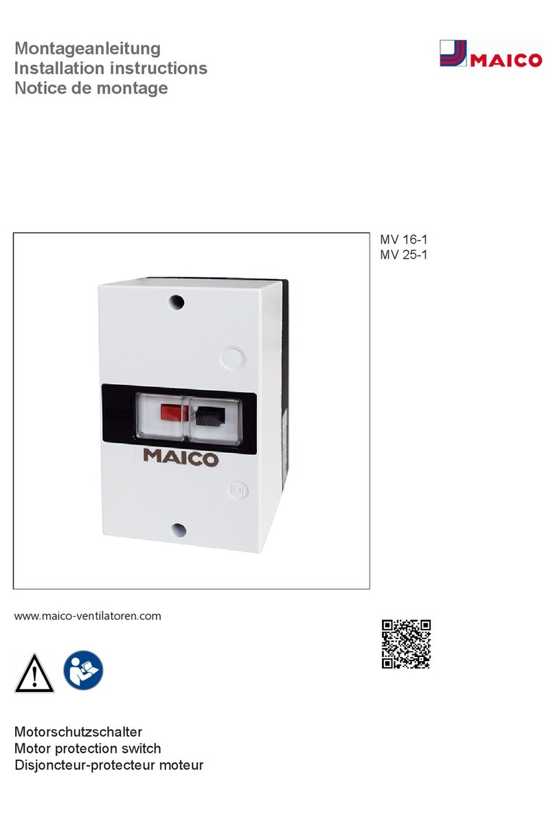
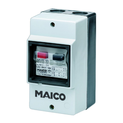
1 Gehäusedeckel mit Spritzwasserschutz
2 AUS-Taste (rot)
3 EIN-Taste (schwarz)
3 Lieferumfang
Motorschutzschalter, 2 Leitungstüllen und diese
Montageanleitung.
4 Bestimmungsgemäße Verwen-
dung
Motorschutzschalter zum Schutz von Einpha-
sen-Wechselstromventilatoren. Mit Haupt-
schütz und Steuersicherung. Für Ventilatoren mit
integriertem Thermoschalter und ausgeführten
Thermokontakten TB. Zur Aufputz-Wandmontage
in Innenbereichen.
Der Motorschutzschalter ist ausschließlich für
den häuslichen Gebrauch und ähnliche Zwecke
vorgesehen.
5 Funktion
Der Motorschutzschalter schützt den Ventilator-
motor vor Überspannung/Überhitzung. Wird die
zulässige Temperatur in der Motorwicklung (Steu-
erstromkreis Thermokontakte TB) überschritten,
fällt das Hauptschütz ab und trennt den Motor
vom Netz. Nach dem Abkühlen der Motorwick-
lung (je nach Ventilator bis zu 30 Minuten) verhin-
dert eine Wiedereinschaltsperre im Gerät das
selbsttätige Einschalten des Motors.
Zum Wiedereinschalten → Störungsbeseitigung
[}4].
6 Sicherheitshinweise
VORSICHT Verletzungsgefahr durch an-
laufenden Ventilator nach einem Netzausfall
oder bei Arbeiten im Gefahrenbereich des
Ventilators.
Der Motorschutzschalter reagiert auf Überhit-
zung, z. B. bei Überspannung. Bei Abkühlung
nach einem Netzausfall kann der Ventilatormotor
automatisch anlaufen. Nicht in den Bereich des
Ventilator-Flügelrades greifen und keine Ge-
genstände in den Bereich des Flügelrades
stecken.
Ventilator generell vom Netz trennen, wenn Sie
im Gefahrenbereich des Ventilators arbeiten (bei
Installations-, Reinigungs-, Wartungs- und Repa-
raturarbeiten).
GEFAHR Explosionsgefahr falls explosi-
onsfähige Gase/Stäube entzündet werden.
Gerät auf keinen Fall in explosionsfähiger Atmo-
sphäre einsetzen.

7 Technische Daten
3
GEFAHR Gefahr bei Nichtbeachtung der
geltenden Vorschriften für Elektroinstallatio-
nen.
Beachten Sie die Sicherheitsregeln der Elektro-
technik. Vor dem Abnehmen von Abdeckungen
und vor Elektroinstallationen alle Versorgungs-
stromkreise abschalten, Netzsicherung ausschal-
ten, die Spannungsfreiheit feststellen, gegen
Wiedereinschalten sichern und ein Warnschild
sichtbar anbringen.
Gerät nur an einer fest verlegten elektrischen In-
stallation anschließen. Leitungstyp und -quer-
schnitt gemäß gemäß DIN VDE 0298-4 auswäh-
len → Technische Daten.
Eine Vorrichtung zur Trennung vom Netz mit min-
destens 3mm Kontaktöffnung je Pol ist vorge-
schrieben. Anschluss gemäß Schaltbild vorneh-
men.
Gerät nur mit auf Typenschild angegebener
Spannung und Frequenz betreiben. PE-Leiter an-
schließen und Verbindung prüfen. betreiben.
Schutzleiterdurchgang am Gehäuse prüfen (VDE
0100-600, VDE 0105-100).
Gerät nur komplett montiert betreiben.
Veränderungen und Umbauten sind unzulässig
und entbinden den Hersteller von jeglicher Ge-
währleistung und Haftung.
Ein beschädigtes Gerät nicht in Betrieb nehmen
und bis zur Instandsetzung den Betrieb verhin-
dern.
Die auf dem Typenschild angegebene Schutzart
ist nur gewährleistet bei bestimmungsgemäßem
Einbau und bei ordnungsgemäßer Einführung der
Anschlussleitung in das Gehäuse.
VORSICHT Vorsicht beim Umgang mit
Verpackungsmaterialien.
Verpackungsmaterial außer Reichweite von Kin-
dern aufbewahren (Erstickungsgefahr bei Ver-
schlucken).
7 Technische Daten
Bemessungsspannung 230VAC
Netzfrequenz 50Hz / 60Hz
Maximalbelastung
(induktive Last)
0,4A
Maximalbelastung
(ohmsche Last)
10A
Max. Vorsicherung 25A(gL)
Max. Verlustleistung ca.6W
Funkentstörung (EN
55011)
VDE 0875, Störgrad N
Max. Leitungsquer-
schnitt
6mm²
Max. Leitungsquer-
schnitt TB/Hilfsschalter
2,5mm²
Schutzart IP55
Schutzklasse II
Einbauart Aufputz
Gewicht 0,6kg
Abmessungen (BxHxT) 80x135x96,5mm
Umgebungstemperatur -25…40°C
Für weitere technische Daten → Typenschild.
8 Montage, Elektrischer Anschluss
Montagehinweise
• Gerät nur auf trockenem, ebenen Untergrund
montieren. Gehäuse nicht verspannen. Einbau-
lage beliebig.
• Montageort außerhalb Verkehrsbereich wählen.
Gerät vor direkter Sonneneinstrahlung schüt-
zen. Auf ausreichende Wärmeabfuhr achten.
Montage
1. Beide Schrauben des Gehäusedeckels lösen,
Gehäusedeckel abnehmen.
2. Beide Haltewinkel abziehen und Schalterein-
satz aus dem Gehäuse nehmen.
3. Entsprechend der Anzahl der Leitungen an
den Sollbruchstellen Leitungsdurchbrüche im
Gehäuse ausbrechen und Leitungstüllen ein-
setzen. Tüllen so einsetzen, dass diese dicht
im Gehäuse anliegen und die Anschlussleitun-
gen dicht umschließen.
4. Gehäuseunterteil an der Wand befestigen.
Geeignetes Befestigungsmaterial ist bauseitig
bereitzustellen.
5. Anschlussleitungen durch die Tüllen in das
Gehäuse führen, Dichtigkeit prüfen.
6. Der Anschluss der Netzspannung muss oben,
der Anschluss des Motors muss unten erfol-
gen. Ein Vertauschen von Ein- und Ausgangs-
seite ist nicht zulässig.
7. Motorschutzschalter gemäß Schaltbild ver-
drahten.
Der Anschluss der Netzspannung muss
oben, der Anschluss des Motors muss unten
erfolgen. Ein Vertauschen von Ein- und Aus-
gangsseite ist nicht zulässig. Thermokontakt
nur an den mit TB bezeichneten Klemmen an-
schließen.

9 Inbetriebnahme
4
8. Schaltereinsatz in das Gehäuse einsetzen,
zum Befestigen beide Haltewinkel einsetzen
und ganz nach unten drücken.
9. Gehäusedeckel aufsetzen und mit beiden
Schrauben befestigen. Auf korrekten Einsatz
der umlaufenden Dichtung im Gehäuseoberteil
achten. ACHTUNG: Kurzschlussgefahr durch
Nässe bei undichtem Gehäuse.
10.Ventilator installieren.
9 Inbetriebnahme
1. Übereinstimmung mit den technischen Daten
kontrollieren → Typenschild.
2. Netzsicherung einschalten, Funktionstest
durchführen.
10 Störungsbeseitigung
Störungsbeseitigung nur durch Elektrofach-
kraft zulässig. Reparaturen nur im Hersteller-
werk zulässig.
Störung: Steuersicherung des Motorschutzschal-
ters hat ausgelöst. Der Ventilatormotor ist vom
Netz getrennt. Eine Wiedereinschaltsperre verhin-
dert das selbsttätige Einschalten des Motors.
Ursache: Überschreitung der zulässigen Tempe-
ratur in der Motorwicklung des Ventilators/ Über-
hitzung der Ventilator-Thermokontakte TB.
Je nach Ventilator bis zu 30 Minuten abwarten.
Die Störung beseitigen, falls die Störung weiterhin
besteht. Zum Wiedereinschalten zuerst die ro-
te Taste und dann die schwarze Taste drücken,
so dass die schwarze Taste einrastet.
Wird der Ventilator eingeschaltet bevor der
Motor abgekühlt ist, erfolgt innerhalb von 1
Minute eine erneute Auslösung.
11 Demontage, Umweltgerechte
Entsorgung
Altgeräte und Elektronikkomponenten dür-
fen nur durch Elektrofachkräfte demontiert
werden. Eine fachgerechte Entsorgung vermei-
det negative Auswirkungen auf Mensch und Um-
welt und ermöglicht eine Wiederverwendung
wertvoller Rohstoffe bei möglichst geringer Um-
weltbelastung.
Entsorgen Sie Elektronikkompo-
nenten nicht über den Hausmüll !
Führen Sie diese einer umweltge-
rechten Entsorgung und Verwertung
über die entsprechenden Annahme-
stellen zu (→ Abfall-Entsorgungsge-
setz).
1. Trennen Sie die Komponenten nach Material-
gruppen.
2. Entsorgen Sie Verpackungsmaterialen (Kar-
ton, Füllmaterialien, Kunststoffe) über entspre-
chende Recyclingsysteme oder Wertstoffhöfe.
3. Beachten Sie die jeweils landesspezifischen
und örtlichen Vorschriften.
Impressum
© Maico Elektroapparate-Fabrik GmbH. Deut-
sche Original-Betriebsanleitung. Druckfehler, Irr-
tümer und technische Änderungen vorbehalten.

MVE 10-1 motor protection switch
5
MVE 10-1 motor protection
switch
1 Preface
Please read these instructions carefully be-
fore installation and using for the first time.
Also read the installation instructions of the
fan to be connected. Follow the instructions.
• Installation, electrical connection, commission-
ing, fault rectification, maintenance and repair
may only be undertaken by qualified electri-
cians in accordance with the applicable elec-
trical engineering regulations → DIN EN
50110-1, DIN EN 55011 (VDE 0875), DIN EN
60204-1, DIN EN IEC 60947-4-1 VDE
0660-102:2020-05 Low voltage switching
devices.
•Requirements for qualified electricians: Spe-
cialist training and knowledge of technical
standards, EU Directives and EU Ordinances.
• Pay attention to the valid accident prevention
regulations.
2 Overview
1 Housing cover with splash water protec-
tion
2 OFF button (red)
3 ON button (black)
3 Scope of delivery
Motor protection switch, 2 cable grommets and
these installation instructions.
4 Intended use
Motor protection switch for protecting the
single-phase AC fans. With main contactor and
control fuse. For fans with integrated thermal
switch and fitted TB thermal contacts. For indoor,
surface-mounted wall installation.
The motor protection switch is only intended for
domestic use and similar purposes.
5 Function
The motor protection switch protects the fan mo-
tor against over-voltage/overheating. If the permit-
ted temperature in the motor winding (control cir-
cuit – TB thermal contact) is exceeded, the main
contactor drops out and disconnects the motor
from the mains. After the motor winding has
cooled down, which can take up to 30 minutes
depending on the fan, a restart interlock in the
unit prevents the automatic switch-on of the mo-
tor.
To switch back on → Fault rectification [}7].
6 Safety instructions
CAUTION Risk of injury due to fan start-
ing up after a power failure or when working
in the fan’s danger zone.
The motor protection switch reacts to overheat-
ing, e.g., in the event of over-voltage. If cooled
after a power failure, the fan motor can start up
automatically. Do not reach into the area
around the fan impeller and do not stick in
objects near the impeller.
Generally disconnect the fan from the power sup-
ply when working in the fan’s danger zone (dur-
ing installation, cleaning, maintenance and repair
work).
DANGER Risk of explosion if explosive
gases/dusts are ignited.
Never use unit in an explosive atmosphere.

7 Technical data
6
DANGER Danger if the relevant regula-
tions for electrical installations are not ob-
served.
Observe the safety rules of electrical engineering.
Before taking off covers and before installing the
electrics, shut down all supply circuits, switch off
mains fuse, check that no voltage is present, se-
cure against being accidentally switched back on
and position a visible warning sign.
Only connect the unit to a permanent electrical
installation. Select cable type and cross-section
in accordance with DIN VDE 0298-4 → Technical
data.
A mains isolation device with contact openings of
at least 3 mm at each pole is mandatory. Make
connections according to wiring diagram.
The unit may only be operated using the voltage
and frequency shown on the rating plate. Con-
nect PE conductor and check the connection.
Check protective-conductor opening on housing
(VDE 0100-600, VDE 0105-100).
Only operate the unit when it is completely in-
stalled.
Modifications and alterations are not permitted
and release the manufacturer from any guaran-
tee obligations and liability.
Do not put a damaged unit into operation and do
not allow it to be operated until repaired.
The degree of protection stated on the rating
plate is only guaranteed if installation is under-
taken correctly and if the connection cable is cor-
rectly guided into the housing.
CAUTION Exercise caution when hand-
ling packaging materials.
Store packaging material out of the reach of chil-
dren (risk of suffocation due to swallowing).
7 Technical data
Rated voltage 230VAC
Power frequency 50 Hz/60 Hz
Maximum loading
(inductive load)
0.4 A
Maximum loading
(ohm resistive load)
10 A
Max. backup fuse 25A(gL)
Max. power loss approx. 6W
Radio interference sup-
pression (EN 55011)
VDE 0875, interference
level N
Max. cable cross-sec-
tion
6 mm²
Max. cable cross-sec-
tion for TB/auxiliary
switch
2.5 mm²
Degree of protection IP55
Protection class II
Type of installation Surface-mounted
Weight 0.6 kg
Dimensions (WxHxD) 80x135x96.5mm
Ambient temperature -25…40°C
For more technical data → rating plate.
8 Installation, electrical connec-
tion
Installation instructions
• Only install unit on a dry, flat surface. Do not
distort housing. Any installation position can be
selected.
• Select installation location outside of traffic
area. Protect unit from direct sunlight. Ensure
sufficient heat dissipation.
Installation
1. Loosen both of the housing cover screws and
remove the housing cover.
2. Pull off both retaining brackets and remove the
switch insert from the housing.
3. Break out cable lead-throughs at the knockout
points in the housing, according to the number
of cables, and insert cable grommets. Insert
the grommets so that they fit tightly against the
housing and around connection cable cables.
4. Mount the lower part of the housing on the
wall. Suitable mounting material is to be
provided by the customer.
5. Guide the connection cables into the housing
through the grommets, check for leak tight-
ness.
6. The connection of the mains voltage must be
at the top, the connection of the motor must be
at the bottom. Swapping the input and output
sides is not permitted.
7. Wire motor protection switch in accordance
with wiring diagram.
The connection of the mains voltage must
be at the top, the connection of the motor
must be at the bottom. Swapping the input
and output sides is not permitted. Only con-
nect thermal contact to terminals marked with
TB.

9 Commissioning
7
8. Insert the switch insert into the housing, insert
both retaining brackets to secure and press all
the way down.
9. Fit housing cover and secure it with both
screws. Make sure the wrap-around seal is
correctly located in the upper part of the hous-
ing. NOTICE: Danger of short-circuits, caused
by moisture, if the housing is not fully sealed.
10.Install the fan.
9 Commissioning
1. Check that the technical data has been ad-
hered to → Rating plate.
2. Switch the mains fuse on, perform a function
test.
10 Fault rectification
Fault rectification may only be undertaken
by a qualified electrician. Repairs may only be
carried out at the manufacturer’s factory.
Fault: Control fuse of the motor protection switch
has triggered. The fan motor is separated from
the mains. A restart interlock prevents the motor
from switching back on automatically.
Cause: Exceeding the temperature permitted in
the fan’s motor winding/overheating of the TB fan
thermal contacts.
Depending on the fan, wait up to 30 minutes.
Rectify the fault if the fault persists. In order to
restart, first press the red button and then the
black button, so that the black button locks into
place.
If the fan is switched back on before the
motor has cooled down, it is retriggered
within 1 minute.
11 Disassembly, environmentally-
sound disposal
Old devices and electronic components may
only be dismantled by qualified electricians.
Proper disposal avoids detrimental impact on
people and the environment and allows valuable
raw materials to be reused with the least amount
of environmental impact.
Do not dispose of electronic com-
ponents in household waste! Dis-
pose of them in an environmentally
friendly manner and recycle them at
the appropriate collection points (→
Waste Management Act).
1. Separate the components according to mater-
ial groups.
2. Dispose of packaging materials (cardboard,
filling materials, plastics) via appropriate re-
cycling systems or recycling centres.
3. Observe the respective country-specific and
local regulations.
Company information
© Maico Elektroapparate-Fabrik GmbH. Trans-
lation of the original German operating instruc-
tions. Misprints, errors and technical changes are
reserved.

Disjoncteur-protecteur moteur MVE10-1
8
Disjoncteur-protecteur moteur
MVE10-1
1 Avant-propos
Veuillez lire attentivement cette notice
avant le montage et la première utilisation. Li-
sez également la notice de montage du venti-
lateur à raccorder. Suivez les instructions.
• Montage, branchement électrique, mise en ser-
vice, élimination des dysfonctionnements, en-
tretien et réparation réservés exclusivement
aux électriciens qualifiés conformément aux
règles électrotechniques → DIN EN 50110-1,
DIN EN 55011 (VDE 0875), DIN EN 60204-1,
DIN EN IEC 60947-4-1 VDE 0660-102:2020-05
dispositifs de commutation basse tension.
•Conditions préalables pour électriciens qua-
lifiés: formation professionnelle et connais-
sance des normes techniques, des directives et
ordonnances de l'UE.
• Respectez les consignes de prévention d'acci-
dents en vigueur.
2 Vue d'ensemble
1 Couvercle de boîtier protégé contre les
projections d'eau
2 Touche ARRÊT (rouge)
3 Touche MARCHE (noire)
3 Volume de fourniture
Disjoncteur-protecteur moteur, 2 manchons de
câble et cette notice de montage.
4 Utilisation conforme
Disjoncteur-protecteur moteur pour la protec-
tion des ventilateurs à courant alternatif mono-
phasé. Avec contacteur général et fusible de
commande. Pour ventilateurs avec interrupteur
thermique intégré et thermocontacts accessibles
de l'extérieur TB. Pour montage mural apparent à
l’intérieur.
Le disjoncteur-protecteur moteur est exclusive-
ment réservé à l'usage domestique et similaires.
5 Fonction
Le disjoncteur-protecteur moteur protège le mo-
teur du ventilateur de la surtension/ surchauffe.
Si la température admissible est dépassée dans
la bobine de moteur (circuit de courant de com-
mande, thermocontacts TB), le contacteur géné-
ral retombe et coupe le moteur du secteur. Après
le refroidissement de la bobine de moteur (jus-
qu'à 30 minutes en fonction du ventilateur), le
verrouillage au réenclenchement de l'appareil
empêche le redémarrage automatique du moteur.
Pour la remise en service → Élimination des dys-
fonctionnements [}10].
6 Consignes de sécurité
PRUDENCE Risque de blessure dû à la
mise en marche des ventilateurs après une
panne de courant ou en cas de travaux dans
le périmètre dangereux du ventilateur.
Le disjoncteur-protecteur moteur réagit à la sur-
chauffe, par ex. en cas de surtension. En cas de
refroidissement après une panne de courant, le
moteur du ventilateur peut redémarrer automati-
quement. Ne pas approcher les mains de l'hé-
lice du ventilateur ni introduire d'objets dans
cette zone.
Couper, en règle générale, le ventilateur du sec-
teur si vous travaillez dans le périmètre dange-
reux du ventilateur (lors des travaux d'installation,
de nettoyage, d'entretien et de réparation).
DANGER Risque d'explosion si des gaz/
poussières explosifs s'enflamment.
Ne jamais utiliser l'appareil dans une atmosphère
explosive.

7 Caractéristiques techniques
9
DANGER Danger en cas de non-respect
des consignes en vigueur relatives aux instal-
lations électriques.
Respectez les règles de sécurité de la technique
électrique. Avant de retirer les caches de protec-
tion et d'effectuer des installations électriques,
couper tous les circuits d'alimentation électrique,
désactiver le fusible secteur, contrôler l'absence
de tension, sécuriser contre toute remise en ser-
vice intempestive et apposer un panneau d'aver-
tissement de manière bien visible.
Raccorder l'appareil uniquement à une installa-
tion électrique permanente. Le type et la section
de la conduite doivent être choisis conformément
à la norme DIN VDE 0298-4 → Caractéristiques
techniques.
Prévoir un dispositif de coupure du secteur avec
une ouverture de contact d'au moins 3mm par
pôle. Effectuer le branchement conformément au
schéma de branchement.
Utiliser exclusivement l'appareil à la tension et à
la fréquence indiquées sur la plaque signalétique.
Raccorder le conducteur PE et contrôler la
connexion. Vérifier le passage de la terre sur le
boîtier (VDE 0100-600, VDE 0105-100).
N'utiliser l'appareil qu'après son montage com-
plet.
Les modifications et transformations sont rigou-
reusement interdites et dégagent le fabricant de
toute responsabilité et garantie.
Ne pas mettre en marche un appareil endomma-
gé et en empêcher l'utilisation jusqu'à réparation
complète.
Le type de protection indiqué sur la plaque signa-
létique est uniquement garanti sous réserve d'un
montage conforme aux prescriptions et de l'inser-
tion correcte du câble de raccordement dans le
boîtier.
PRUDENCE Manipuler les matériaux
d'emballage avec prudence.
Conserver le matériel d'emballage hors de portée
des enfants (risque d'étouffement en cas d'inges-
tion).
7 Caractéristiques techniques
Tension de service 230V CA
Fréquence du secteur 50 Hz/ 60 Hz
Charge maximale
(charge inductive)
0,4 A
Charge maximale
(charge ohmique)
10 A
Préfusible max. 25A(gL)
Puissance dissipée
max.
env.6W
Antiparasitage (EN
55011)
VDE 0875, degré de
parasitage N
Section de câble max. 6mm²
Section de câble max.
TB/ interrupteur auxi-
liaire
2,5mm²
Type de protection IP55
Classe de protection II
Type de montage montage apparent
Poids 0,6kg
Dimensions (lxhxp) 80x135x96,5mm
Température ambiante -25…40°C
Pour des caractéristiques techniques supplémen-
taires → Plaque signalétique.
8 Montage, branchement élec-
trique
Consignes de montage
• Monter l'appareil exclusivement sur un support
sec et plan. Ne pas soumettre le boîtier à trac-
tion. Position de montage au choix.
• Sélectionner le lieu d'installation à l'extérieur du
trafic. Protéger l'appareil de l'exposition directe
aux rayons du soleil. Veillez à respecter une
évacuation suffisante de la chaleur.
Montage
1. Desserrer les deux vis du couvercle de boîtier
et déposer le couvercle de boîtier.
2. Retirer les deux équerres de fixation et sortir
l'insert d'interrupteur du boîtier.
3. Selon le nombre de conduites, détacher les
passages conduites au niveau des points des-
tinés à la rupture du boîtier et fixer les man-
chons de câble. Fixer les manchons de sorte
qu'ils soient bien appliqués sur le boîtier et en-
serrent fermement les câbles de raccorde-
ment.
4. Fixer la partie inférieure du boîtier au mur. Le
matériel de fixation adéquat est à fournir par le
client.
5. Amener les câbles de raccordement dans le
boîtier via les manchons, vérifier l'étanchéité.
6. Le raccordement de la tension secteur doit
être effectué au-dessus, celui du moteur en
dessous. Une permutation des côtés d'entrée
et de sortie n'est pas autorisée.

9 Mise en service
10
7. Câbler le disjoncteur-protecteur moteur
conformément au schéma de branchement.
Le raccordement de la tension secteur doit
être effectué au-dessus, celui du moteur en
dessous. Une permutation des côtés d'entrée
et de sortie n'est pas autorisée. Ne raccorder le
thermocontact que sur les bornes portant la
désignation TB.
8. Introduire l'insert d'interrupteur dans le boîtier.
Utiliser les s deux équerres de fixation pour
fixer et enfoncer vers le bas.
9. Poser le couvercle du boîtier et le fixer à l'aide
des deux vis. Veiller au positionnement correct
du joint d'étanchéité sur tout le pourtour de la
partie supérieure du boîtier. ATTENTION:
risque de court-circuit provoqué par l'humidité
si le boîtier n'est pas étanche.
10.Installer le ventilateur.
9 Mise en service
1. Contrôler la concordance avec les caractéris-
tiques techniques → Plaque signalétique.
2. Activer le fusible secteur, effectuer un test de
fonctionnement.
10 Élimination des dysfonctionne-
ments
Élimination des dysfonctionnements exclu-
sivement réservée à des électriciens qualifiés.
Réparations exclusivement réservées à l'usine
du constructeur.
Dysfonctionnement: le fusible de commande
du disjoncteur-protecteur moteur a déclenché. Le
moteur de ventilateur est coupé du secteur. Un
verrouillage au réenclenchement empêche le re-
démarrage automatique du moteur.
Cause: dépassement de la température admis-
sible dans la bobine de moteur du ventilateur/
surchauffe des thermocontacts du ventilateur TB.
Selon le ventilateur, attendre jusqu'à 30 minutes.
Éliminer le dysfonctionnement s'il persiste. Pour
la remise en service, appuyer en premier lieu
sur la touche rouge, puis sur la touche noire
de manière à ce que la touche noire s'enclenche.
Si le ventilateur est allumé avant le refroi-
dissement du moteur, le ventilateur se dé-
clenche à nouveau après 1 minute.
11 Démontage, élimination dans
le respect de l'environnement
Les appareils usagés et composants élec-
triques ne doivent être démontés que par des
électriciens qualifiés. Une élimination dans les
règles de l'art évite les effets négatifs sur l'homme
et l'environnement et permet un recyclage de ma-
tières premières précieuses, tout en minimisant
l'impact sur l'environnement.
Ne pas éliminer les composants
électriques avec les ordures ména-
gères! Apportez-les aux points de
collecte pouvant assurer une élimina-
tion et un recyclage respectueux de
l'environnement (→ législation
concernant la gestion des déchets).
1. Triez les composants selon les groupes de
matériaux.

Mentions légales
11
2. Éliminez les matériaux d'emballage (carton,
matériaux de remplissage, plastiques) via des
systèmes de recyclage et des déchetteries
adaptés.
3. Respectez les prescriptions nationales et lo-
cales.
Mentions légales
© Maico Elektroapparate-Fabrik GmbH. Tra-
duction du mode d'emploi original allemand. Sous
réserve de fautes d'impression, d'erreurs et de
modifications techniques.

Maico Elektroapparate-Fabrik GmbH
Steinbeisstr. 20
78056 Villingen-Schwenningen
Deutschland
Service +4977206940
0185.1270.0001_RLF.9_05.23_DSW
Table of contents
Languages:
Other Maico Switch manuals