Maico XS 1 Quick reference guide

Funkschalter XS 1
XS 1 Radio switch
Commutateur radio XS 1
Montage- & Bedienungsanleitung
Assembly & Operating Instructions
Instructions de montage &
Mode d´emploi
Funkschalter XS 1
Der Funkschalter XS 1 ermöglicht eine draht-
lose Fernbedienung von XE 1-Funkempfängern.
Der XS 1 ist als 1-Kanal-Funkschalter ausgelegt.
Mit dem eingesetzten Schaltereinsatz [4] lassen
sich die Ventilatoren ein- und ausschalten.
MAICO haftet nicht für Schäden, die durch
bestimmungswidrigen Gebrauch verursacht
werden.
Sicherheitshinweise
•Montage, Elektrischer Anschluss und Re-
paraturen dürfen nur von Elektro-
fachkräften vorgenommen werden.
•Bei der Elektroinstallation und Montage sind
die einschlägigen Vorschriften, besonders DIN
VDE 0100 mit den entsprechenden Teilen zu
beachten.
•Batterien gehören nicht in Kinderhände. Sofort
einen Arzt aufsuchen, wenn Knopfzellen ver-
schluckt werden.
•Verbrauchte Batterien bei einer Sammelstelle
abgeben, nicht über den Hausmüll entsorgen.
•Die Bauart des Funkschalters entspricht den
sicherheitstechnischen Anforderungen des
VDE im Rahmen des Gerätesicherheits-
gesetzes sowie den einschlägigen Bestim-
mungen der EG-Richtlinien.
•Diese Anleitung nach der Montage dem Kun-
den aushändigen!
Änderungen vorbehalten
Subject to change
Sous réserve de modification 0700
Hinweise zum Funkbetrieb
•Der Betrieb des Funkschalters XS 1 ist in allen
EU-Staaten zulässig.
•Das Zusammenschalten dieser Funkanlage
mit anderen Kommunikationsnetzen ist nur im
Rahmen von nationalen Gesetzen zulässig.
•Diese Funkanlage darf nicht zur Kommunika-
tion über Grundstückgrenzen hinweg genutzt
werden.
•Bei Betrieb innerhalb Deutschlands sind die
Hinweise aus der Allgemeinzuteilung im Amts-
blatt „Vfg 73/200“ zu beachten.
Übersicht
1 Aufputzgehäuse
2 Sender
2.1 Batteriefach,2 Batte-
rien (CR 2032, 3V)
2.2 DIP-Schalter
2.3 Antenne
3 Schutzblende
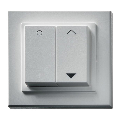
4 Schaltereinsatz
4.1 Taste EIN, oben
4.2 Taste AUS, unten

Funkübertragung
Die Funkübertragung erfolgt auf einem nicht
exklusiven Übertragungsweg. Störungen kön-
nen deshalb nicht ausgeschlossen werden.
Nicht geeignet ist die Funkübertragung zum
Schalten von Sicherheitsanwendung, z. B.
für Not-Aus- oder Notrufeinrichtungen.
Die Sendereichweite des Funkschalters beträgt
max. 100 m im Freifeld. Sie ist jedoch abhängig
von den baulichen Gegebenheiten des Objek-
tes und fällt in der Regel geringer aus:
Trockenes Material Durchdringung
Holz, Gips, Gipskartonplatten ca. 90%
Backsteine, Press-Spanplatten ca. 70%
Armierter Beton ca. 30%
Metall, Metallgitter, Alu-Kaschierung ca. 10%
Montage
Der Funkschalter wird im Aufputzgehäuse [1]
oder in eine bauseitig bereitzustellende Unter-
putzdose eingebaut.
1. Aufputzgehäuse [1] mit geignetem Befes-
tigungmaterial an der Wand befestigen. Ggf.
im Gehäuse gewünschte Solldurchbrüche
durchbohren. Alternativ kann das Gehäuse
mit dem beigefügten Klebeeinsatz an einer
Scheibe befestigt werden.
2. Sender [2] im Aufputz- bzw. Unterputz-
gehäuse mit 2 Schrauben befestigen. Unbe-
dingt auf die Kennzeichnung „TOP“ achten,
diese muss oben stehen.
3. Antenne [2.3] im Aufputzgehäuse [1] ober-
halb der Stege verlegen. Unterputz: Um max.
Sendeleistung beim Einbau in UP-Dose zu
erhalten, die Antenne wenn möglich vom
Sender entfernt, frei gestreckt und mit Ab-
stand zu großflächigen Metallteilen (Tür-
rahmen etc.) verlegen. Auf keinen Fall die
Antenne knicken, abisolieren, kürzen
oder verlängern.
4. Am DIP-Schalter [2.2] den Schalter 1 „Batt.“
auf ON stellen.
5. DIP-Schalter-Positionen prüfen. Einstellung
für alle 4 DIP-Schalter = rechts.
6. Schaltereinsatz [4] in Schutzblende [3] ein-
legen und gesamte Einheit vorsichtig auf
Sender [2] aufstecken, bis die Federn ein-
rasten. Darauf achten, dass die 10-polige
Steckerleiste und die beiden Federn nicht
beschädigt werden.
Funkempfänger einlernen
Hierfür muss der Funkempfänger installiert
und der Ventilator angeschlossen sein,
siehe auch Funkempfänger-Anleitung.
Der Funkempfänger wird auf den Sendekanal
(Sendefrequenz) des Funksenders abgestimmt,
in dem er ein Funktelegramm des Senders ein-
lernt.
Einem Sendekanal lassen sich unbegrenzt viele
Funkempfänger zuordnen, die Zuordnung er-
folgt im jeweiligen Empfänger.
Zum Einlernen den Höchstabstand zwischen
Sender und Empfänger von max. 5 m sowie den
Mindestabstand von 1 m beachten.
Ggf. mit der ausgebauten Sender/Schalterein-
satz-Einheit direkt an den Empfänger gehen. Die
Komponenten nach dem Einlernen wieder mon-
tieren.
1. Funkempfänger in den Lernmodus schalten.
Dazu am Empfänger die Taste ON/OFF ca.
5 Sek. drücken, bis die rote LED „Prog.“
blinkt und der bereits eingeschaltete Ventila-
tor ausschaltet.
2. Kanal innerhalb von ca. 1 Minute einlernen.
Am Funksender XS 1 mit Taste [4.1] ein
Funktelegramm auslösen.
3. Am Funkempfänger leuchtet die rote LED
„Prog.“ ständig, das Funktelegramm ist
empfangen. Eine schnell blinkende LED zeigt
einen Löschvorgang an => Einlernvorgang
wiederholen.
4. Am Funkempfänger zweimal die Taste ON/
OFF drücken.
5. Funktion mit Taste [4.1] und Taste [4.2]
prüfen. Fertig !
Wird ein bereits eingelernter Sendekanal noch-
mals eingelernt, wird diese Kanalzuordnung im
Emfänger gelöscht. Die rote LED „Prog.“ blinkt
schnell. Kanalzuordnungen müssen einzeln ge-
löscht werden.

Bedienung
Bei Tastendruck der Taste [4.1] des Schalterein-
satzes wird ein Funktelegramm gesendet.
•Ventilator einschalten: Taste [4.1] drücken
•Ventilator ausschalten: Taste [4.2] drücken
Werden mehrere Tasten gleichzeitig gedrückt,
wird kein Funktelegramm gesendet.
Störungen/Beseitigung
Ventilator lässt sich mit dem Funkschalter
nicht mehr einschalten.
Batterien im Sender [2] prüfen und ggf. austau-
schen.
Batteriewechsel
Achtung: Der Funkschalter XS 1 ist mit zwei
Lithium-Knopfzellen (CR 2032) ausgestattet.
Batterien stets zusammen austauschen – alte und
neue Batterien nie gleichzeitig verwenden.
1. Schaltereinsatz [4] und Schutzblende [3]
vorsichtig vom Sender [2] abziehen.
2. DIP-Schalter 1 auf Position OFF stellen.
3. Altbatterien im Batteriefach [2.1] entfernen
und umweltfreundlich entsorgen.
4. Neue Batterien einsetzen, siehe Abb. auf
Sender [2]. Dabei auf korrekte Polarität
achten. Es dürfen nur Batterien identi-
schen Typs eingesetzt werden.
5. Batteriefach verschließen, DIP-Schalter 1 auf
Position ON stellen, Schaltereinsatz [4] und
Schutzblende [3] anbringen.
Technische Daten
Spannungsversorgung 6 V=
– Batterien (Lithium-Knopfzellen) 2x CR 2032
– Batterielebensdauer ca. 3 Jahre
Sendefrequenz 433,42 MHz, ASK
Sendereichweite ca. 100 m (Freifeld)
Temperaturbereich 0 °C ... 55 °C
Rel. Luftfeuchtigkeit max. 80%
XS 1 Radio switch
The XS 1 Radio switch enables a wireless
remote control of XE 1 radio receivers.
The XS 1 is designed as a 1-channel radio
switch. Fans can be switched on and off with the
switch insert [4].
MAICO accepts no liability for damages caused
by non-authorised use.
Safety instructions
•Assembly, electrical connection work and
repairs should only be carried out by
qualified electricians.
•During electrical installation and assembly,
ensure compliance with the corresponding
directives, in particular the pertinent sections
of DIN VDE 0100.
•Batteries should be kept out of the reach of
children. Seek medical advice immediately if
a button cell battery is swallowed.
•Dispose of spent batteries correctly, they do
not belong in general domestic refuse.
•The radio receiver is designed in accordance
with VDE safety requirements in the framework
of the equipment safety laws as well as the
pertinent regulations laid down in the EU
Guidelines.
•Please give these instructions to the customer
after completing installation.

Instructions in respect of radio operation
•The XS 1 radio switch may be used in all
European Union countries.
•The combination of this radio equipment with
other communication networks is only
permitted within the framework as laid down
by national statutes.
•This radio equipment may not be used for
communication that goes beyond property
boundaries.
•When used within Germany, you must take
note of and abide by the instructions given in
the relevant section of the Official Journal „Vfg
73/200“.
Overview
1 Surface-mounted housing 3 Protective cover
2 Transmitter 4 Switch insert
2.1 Battery compartment, 4.1 Switch ON, up
2 batteries (CR 2032, 3V) 4.2 Switch OFF, down
2.2 DIP switch
2.3 Antenna
Radio transmission
Radio transmission is carried out over a non-
exclusive transmission path. The possibility of
interference cannot be ruled out.
Radio transmission is not suitable for the
switching of safety equipment, such as
emergency cut-out switches or emergency
alarm call equipment.
In a clear area, the transmission range of the
radio switch is a maximum of 100 metres. This
is however, dependant on the construction
environment of the object in question and as a
rule, is less than this:
Dry material Penetration
Wood, plaster, plasterboard approx. 90%
Bricks, chipboard approx. 70%
Reinforced concrete approx. 30%
Metal, metal grille,
aluminium lamination approx. 10%
Installation
The radio switch is installed in a surface-mounted
housing [1] or in a recessed-mounted box, to be
supplied by the customer.
1. Secure the surface-mounted housing [1] to
the wall with appropriate material. If required,
holes can be drilled in the housing or
alternatively, it can be fixed to a plate with the
adhesive provided.
2. Fix the transmitter [2] into a surface- or re-
cessed-mounted housing with 2 screws. Make
sure the side marked „TOP“ is uppermost.
3. Insert the antenna [2.3] into the surface-
mounted housing above the plate. Concealed
mounting: In order to achieve maximum
reception performance, install the antenna if
possible remote from the receiver, fully
extended and away from any large metal
surfaces, such as door frames, etc. Under
no circumstances should the antenna be
bent, uninsulated, shortened or leng-
thened.
4. Move switch 1 „Batt“ on the DIP switch [2.2]
to ON.
5. Check the DIP switch positions. All 4 DIP
switches should be set to the right.
6. Position the switch insert [4] into the protective
cover [3] and plug the whole unit carefully
onto the receiver [2], until the springs click
into place. Make sure that the 10 pin plug
socket and the two springs are not damaged.
Setting up the radio receiver
The radio receiver must be installed and the
fan must be connected. Please refer also to
the radio receiver instructions.
The radio receiver is tuned to the transmission
channel (transmission frequency) of the trans-
mitter by „learning“ a radio telegram from the
transmitter.
An unlimited number of radio receivers can be
assigned to one transmission channel. The
assignment is made in each corresponding
receiver.

Please take the maximum distance of 5 metres
and the minimum distance of 1 metre between
the transmitter and receiver into account when
setting up.
If necessary, use the dismantled receiver/switch
insert unit directly with the receiver. When set up
is complete, reassemble the unit again.
1. Switch the receiver to set-up mode by
pressing the ON/OFF switch for approx. 5
seconds until the red „Prog“ LED flashes
and the fan that is already switched on,
switches off.
2. Set up the channel within approx. 1 minute.
Trigger a radio telegram at the XS 1 transmitter
by pressing the key [4.1].
3. If the red LED „Prog.“ is permanently lit, the
radio telegram has been received. If the LED
flashes quickly, this indicates that a delete
procedure is in progress and you should
repeat the set-up procedure.
4. Press the ON/OFF button at the receiver
twice.
5. Check for correct functioning with buttons
[4.1] and [4.2]. You’re done!
If a transmission channel that has already been
set up is set up again, this channel assignment
is deleted in the receiver. The red LED „Prog.“
flashes quickly. Channel assignments have to
be deleted individually.
Operation
A radio telegram is sent when [4.1] is pressed
•Switch fan on: Press [4.1]
•Switch fan off: Press [4.2]
No radio telegram is sent if several keys are
pressed at once.
Problems/Solutions
The fan cannot be switched on any more
with the radio switch.
Check the batteries in the transmitter [2] and
change them if necessary.
Changing the batteries
Please note: The XS 1 radio switch requires two
lithium button cell CR2032 batteries. Always
change both batteries together. Never use old
and new batteries at the same time.
1. Carefully remove the switch insert [4] and the
protective cover [3] from the transmitter [2].
2. Switch DIP switch 1 to the OFF position.
3. Remove the old batteries from the battery
compartment [2.1] and dispose of them in
an environmentally-aware way.
4. Insert the new batteries by reference to the
diagram on the transmitter [2]. Ensure that
the batteries are entered in the right
position. You should only use batteries
of the same type.
5. Close the battery compartment; bring DIP
switch to the ON position; reassemble the
switch insert [4] and the protective cover [3].
Technical Data
Power supply 6 V=
– Batteries (Lithium button cells) 2x CR 2032
– Battery working life approx. 3 years
Transmission frequency 433.42 MHz,
ASK
Transmission range approx. 100 m
(clear area)
Temperature range 0 °C ... 55 °C
Relative humidity max. 80%

Commutateur radio XS 1
Le commutateur radio XS 1 permet de com-
mander des récepteurs radio sans fil et à distance.
Le XS 1 est conçu en tant que commutateur ra-
dio à 1 canal. L’insert de commutation intrégré [4]
permet de mettre les ventilateurs en et hors service.
MAICO décline toute responsabilité pour des
dommages qui résultent d’une utilisation non
conforme.
Consignes de sécurité
•Le montage, le branchement électrique et
tous travaux de réparation doivent
uniquement être effectués par des
électriciens qualifiés.
•Lors de l’installation électrique et du montage,
il faut respecter les règles de l’art, notamment
la norme DIN VDE 0100 avec ses parties
correspondantes.
•Tenez les piles à l’écart des enfants. Consulter
immédiatement un médecin si une pile plate
a été avalée.
•Rapporter les piles usées à un point de
collecte, ne pas les éliminer avec les ordures
ménagères.
•Le type de construction de ce commutateur
radio répond aux normes du VDE en matière
de sécurité technique dans le cadre de la loi
sur la sécurité des appareils ainsi que des
dispositions notoires des directives CE.
•Cette notice doit être remise au client après le
montage.
Remarques relatives au
fonctionnement radio
•L’utilisation du commutateur radio XS 1 est
autorisée dans tous les pays de l’UE.
•Le couplage de cette installation radio avec
d’autres réseaux de communication doit
impérativement respecter le cadre des lois
nationales en vigueur.
•Cette installation radio ne doit pas être utilisée
au-delà des bornes d’une propriété foncière.
•Lorsque vous utilisez cet appareil en Alle-
magne, vous devez respecter les consignes
de l’attribution générale parues dans le journal
officiel „Vfg 73/2000)
Vue d’ensemble
Transmission radio
La transmission radio s’effectue sur une voie de
transmission non exclusive. Par conséquent,
on ne peut exclure des dysfonctionnements.
La transmission radio ne convient pas pour
la commande d’applications de sécurité,
par ex. pour les dispositifs d’arrêt d’urgence
ou d’appel au secours.
La portée de la commande radio est de 100 m
max. en champ libre (sans obstacle). Elle est
néanmoins dépendante de la situation
architecturale de l’objet et est en règle générale
inférieure.
Matériaux secs Pénétration
Bois, plâtre, placoplâtre env. 90%
Briques, panneaux agglomérés env. 70%
Béton armé env. 30%
Métal, grille métallisée, placage alu env. 10 %
Montage
Le commutateur radio est monté dans un boîtier
apparent [1] ou dans un boîtier encastré à
fournir sur site.
1. Fixer le boîtier apparent [1] au mur avec un
matériel de fixation approprié. Le cas échéant,
percer les passages contraints souhaités.
Le boîtier peut être fixé alternativement contre
une vitre avec l’insert pour le collage fourni.
2. Fixer l’émetteur [2] à l’aide de deux vis dans
le boîtier apparent ou encastré. Il faut
impérativement respecter le marquage „TOP“
qui doit se trouver en haut.
1 Boîtier pour installation
apparente
2 Emetteur
2.1 Compartiment à piles
2 piles (CR 2032, 3 V)
2.2 Commutateur DIP
2.3 Antenne
3 Cache de protection
4 Insert de
commutation
4.1 Touche MARCHE,
en haut
4.2 Touche ARRET,
en bas

3. Mettre l’antenne [2.3] en place au-dessus
des barrettes dans le boîtier apparent [1].
Boîtier encastré : Afin d’obtenir la capacité
d’émission maximale lors d’un montage
encastré, l’antenne sera à placer éloignée
autant que possible du récepteur, sans
obstacle et avec une distance par rapport à
des surfaces métallisées importantes
(huisserie de porte etc.). En aucun cas il ne
faut plier l’antenne, ni la dénuder, rac-
courcir ou rallonger.
4. Régler l’interrupteur 1 „Batt.“ au commutateur
DIP [2.2] sur ON.
5. Vérifier les positions du commutateur DIP.
Réglage pour tous les 4 commutateurs
DIP = à droite.
6. Insérer l’insert de commutation [4] dans le
cache de protection [3] et placer toute l’unité
avec précaution sur l’émetteur [2] jusqu’à ce
que les ressorts s’enclenchent. Il faut veiller
à ne pas endommager la barrette de bornes
à 10 broches ou les deux ressorts.
„Apprentissage“ de l’émetteur radio
Pour ce faire, l’émetteur radio doit être
installé et le ventilateur raccordé,
voir également la notice d’utilisation du
récepteur radio.
Le récepteur radio est adapté au canal d’émission
(fréquence d’émission) de l’émetteur radio en lui
„apprenant“ un radiotélégramme de l’émetteur.
Un nombre quelconque de récepteurs radio
peut être attribué à un canal d’émission; cette
attribution s’effectue dans le récepteur concerné.
Lors de cet apprentissage il faut respecter la
distance maximale entre émetteur et récepteur
de 5 m max. ainsi que la distance minimale de
1 m.
Le cas échéant, il faut s’approcher directement
du récepteur avec l’émetteur/unité commutateur
démonté. Après l’apprentissage il faut remonter
les composants.
1. Mettre le récepteur radio en mode appren-
tissage. Pour ce faire, appuyer pendant 5 sec.
env. sur la touche ON/OFF du récepteur
jusqu’à ce que le voyant DEL „Prog.“ clignote
et que le ventilateur déjà en service s’arrête.
2. Apprendre le canal lors d’une durée d’env.
1 minute.
Déclencher un radiotélégramme avec la
touche [4.1] de l’émetteur radio XS 1.
3. Le voyant DEL rouge „Prog.“ du récepteur
radio est allumé en permanence, le radio-
télégramme est reçu. Un voyant DEL à
clignotement rapide indique une procédure
d’effacement => il faut répéter la procédure
d’apprentissage.
4. Appuyer deux fois sur la touche ON/OFF du
récepteur radio.
5. Vérifier le bon fonctionnement à l’aide des
touches [4.1] et [4.2]. C’est terminé !
Au cas ou un canal d’émission déjà appris est
appris de nouveau, cette attribution de canal est
effacée dans le récepteur. Le voyant DEL rouge
„Prog.“ clignote rapidement. Il faut effacer les
attributions de canal une par une.
Commande
L’appui sur la touche [4.1] de l’insert de com-
mutation déclenche l’envoi d’un radiotélé-
gramme.
•Mettre le ventilateur en marche: Appuyer sur
la touche [4.1]
•Arrêter le ventilateur: Appuyer sur la touche [4.2]
Au cas où plusieurs touches sont actionnées en
même temps, aucun radiotélégramme n’est
envoyé.
Pannes/Remèdes
Il est impossible de mettre le ventilateur en
marche à l’aide du commutateur radio.
Vérifier les piles dans l’émetteur [2] et les
remplacer, le cas échéant.

Changement de piles
Attention: Le commutateur radio XS 1 est équipé
de deux piles plates à lithium (CR 2032). Il faut
toujours remplacer les deux piles simultanément
– ne jamais utiliser des piles neuves et des piles
usagées en même temps.
1. Enlever l’insert de commutation [4] et le
cache de protection [3] de l’émetteur [2] en
tirant doucement.
2. Mettre le commutateur DIP 1 sur la position
OFF.
3. Enlever les piles usagées du compartiment
à piles [2.1] et les éliminer dans le respect
de l’environnement.
4. Mettre des piles neuves en place, cf. fig. sur
l’émetteur [2]. Veillez alors à respecter
les polarités. Il faut impérativement
utiliser des piles du même type.
5. Fermer le compartiment à piles, mettre le
commutateur DIP sur la position ON, remettre
l’insert du commutateur [4] et le cache de
protection [3] en place.
Caractéristiques techniques
Alimentation en tension 6 V=
– piles (piles plates lithium) 2x CR 2032
– Durée de vie de piles env. 3 ans
Fréquence d’émission 433,42 MHz, ASK
Portée d’émission env. 100 m
(sans obstacle)
Plage de températures 0 °C ... 55 °C
humidité de l’air relative max. 80% Maico Elektroapparate-Fabrik GmbH · Steinbeisstr. 20
D-78056 Villingen-Schwenningen
Besuchen Sie uns auch im Internet
– Maico-Homepage
➜➜➜
www.maico.de
– Brandschutzlösungen
➜➜➜
www.aeroduct.de
You will also find us in the Internet
– Maico Homepage
➜➜➜
www.maico.de
– Fire protection solutions
➜➜➜
www.aeroduct.de
Rendez-nous visite sur Internet
– Site Maico
➜➜➜
www.maico.de
– Solutions dans le domaine de
de lutte contre les incendies
➜➜➜
www.aeroduct.de
0185.0995.0000 / 11.03
This manual suits for next models
1
Table of contents
Languages:
Other Maico Switch manuals