MAIOR Levante User manual

Maior Levante
Instruction Manual
Rev 1.0 - 05/2019
Eurotecno srl
Via Proventa 120/1 - 48018 Faenza (RA) - Italy | Tel. +39 0546 646821 | info@maiormover.it

ADDRESS:
MAIOR - EUROTECNO SRL
ADDRESS:
Via Proventa, 120/1
48018 Faenza (RA) - Italy
Tel. +39 0546 646821
DOCUMENT TYPE:
Instruction Manual
PRODUCT:
Levante
YEAR OF CONSTRUCTION:
2019
CONFORMITY ':

Warnings
This manual contains the instructions needed to successfully perform the installation, the machine operation
and maintenance.
To safeguard the operator's safety and to avoid any possible damage to the equipment it is essential to have
taken knowledge of the entire manual before taking any action.
This manual is to be considered part of the machine and must therefore follow the machine's life cycle also
in the case of transfer of the same to another user.
This manual must be intact and readable in its entirety; each person authorized to use the equipment or
installation and/or maintenance must know the location and be able to consult it at any time.
Please refer to our latest version of the manual here:https://www.maiormover.it/area-riservata/
All machines are subjected to testing prior to shipment.
It is forbidden to make any kind of changes to the machine.
Any use of the machine different from what is expressly provided by this manual as potentially dangerous.
EUROTECNO SRL accepts no responsibility for the improper use of the machine.
Any damage to the machine or property derived from the infringement of the provisions contained herein or
direct or indirect tampering of any Maior component, will make the warranty invalid.
For each of all communication inherent to the machine, please always quote the serial number on the
nameplate on the machine (see Sec. 1.2)

IT
4
Summary
Warnings............................................................................................................................................................ 3
1. Product ....................................................................................................................................................... 5
1.1. Intended uses .................................................................................................................................... 5
1.2. package ............................................................................................................................................. 6
1.2.1. Package Contents ..................................................................................................................... 6
1.3. Machine description........................................................................................................................... 6
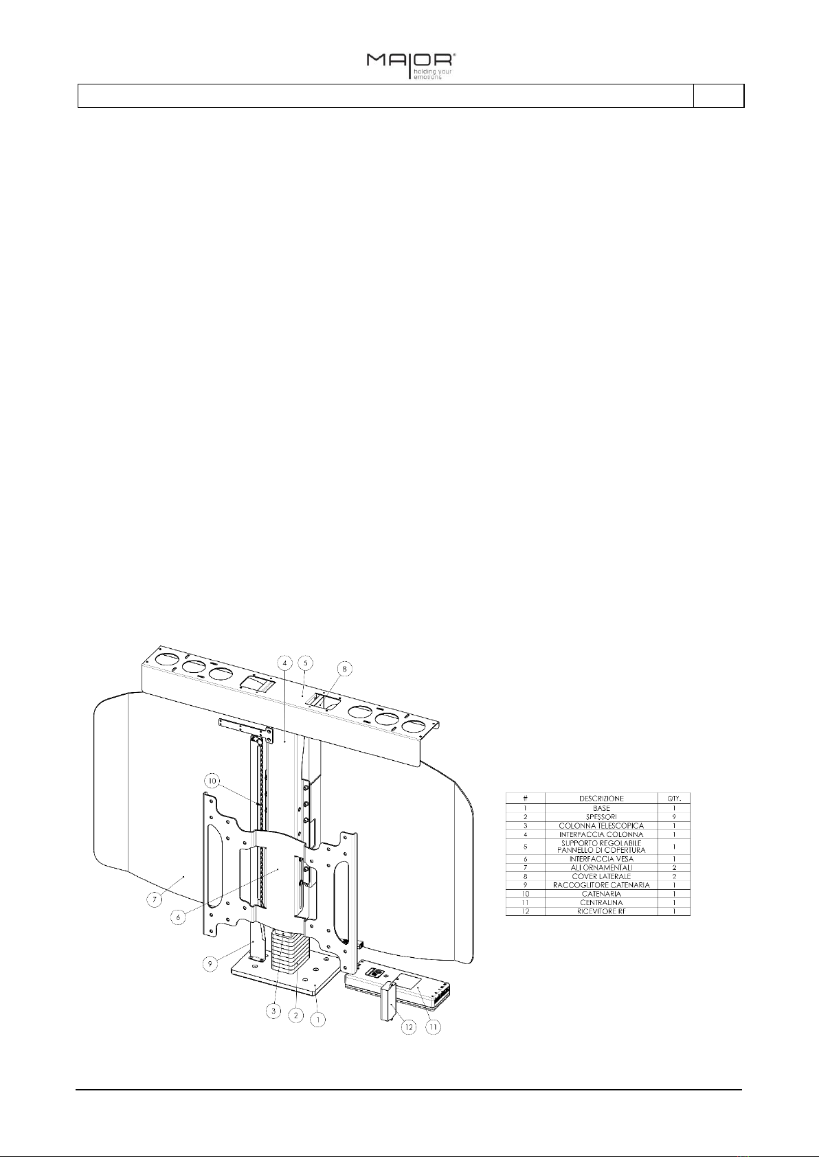
1.3.1. Components and knots.............................................................................................................. 6
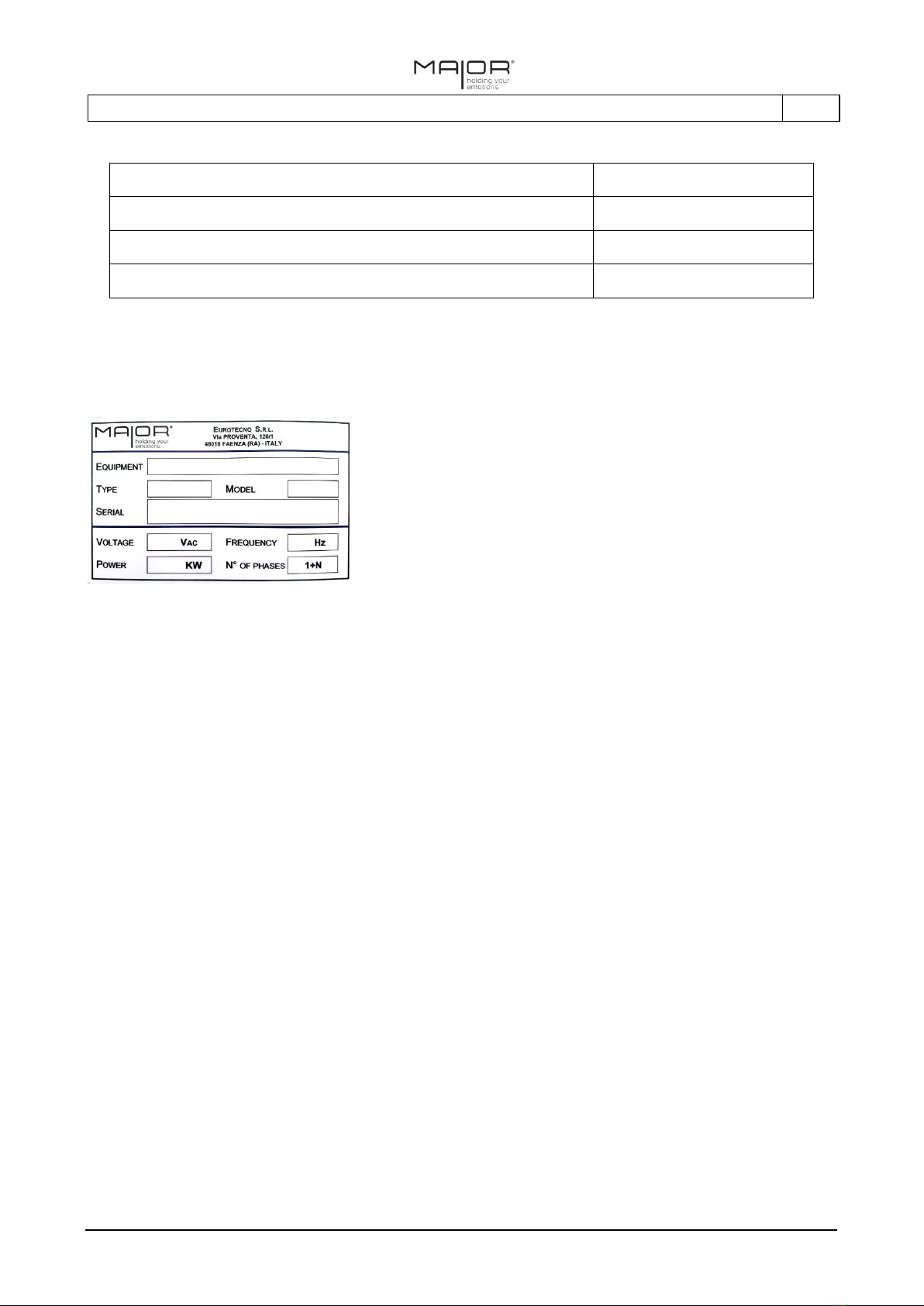
1.3.2. Identification of the machine...................................................................................................... 7
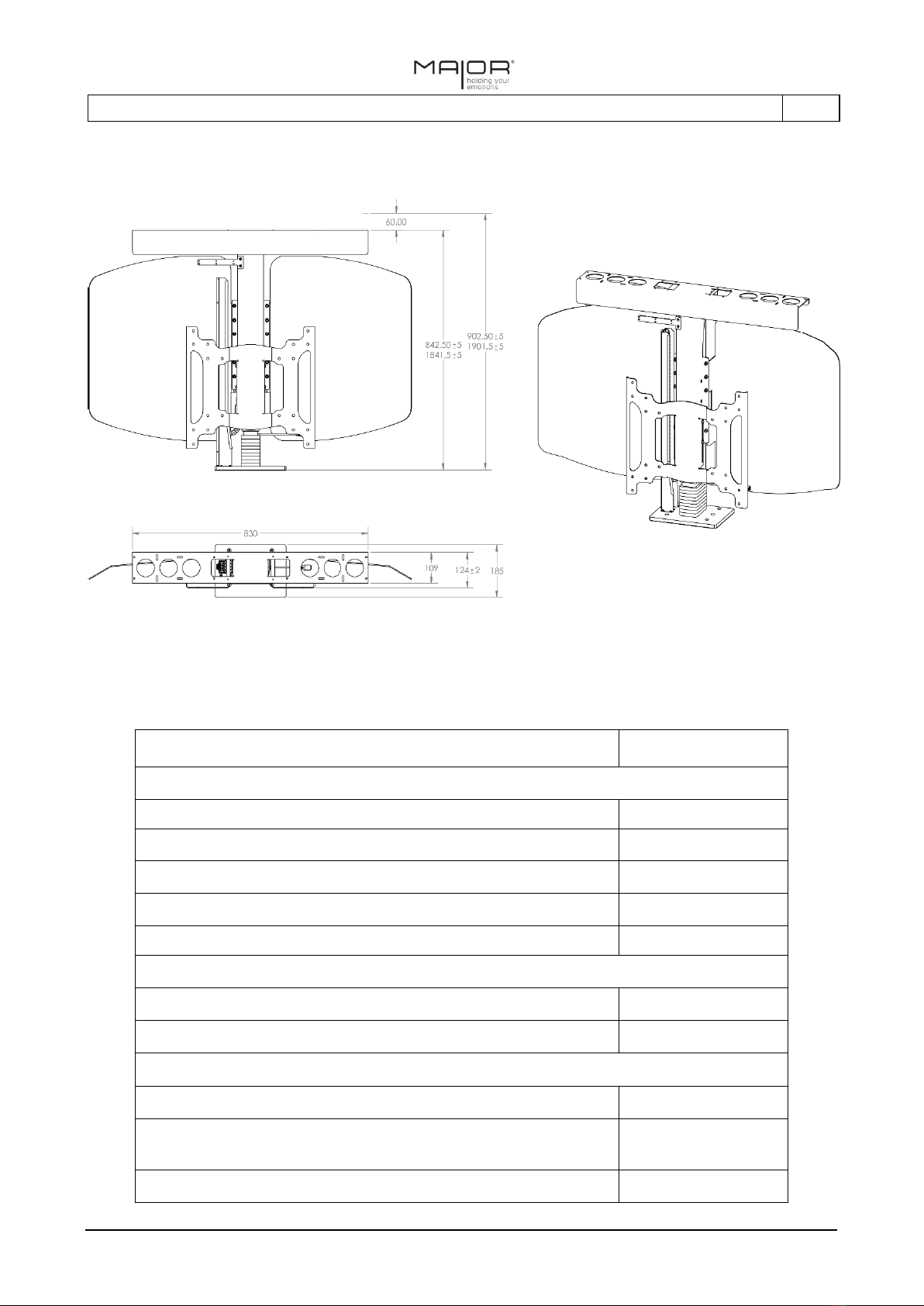
1.3.3. Dimensions and technical data.................................................................................................. 8
1.3.4. Linak Actuator DL12XL.............................................................................................................. 9
1.3.5. motor lead.................................................................................................................................. 9
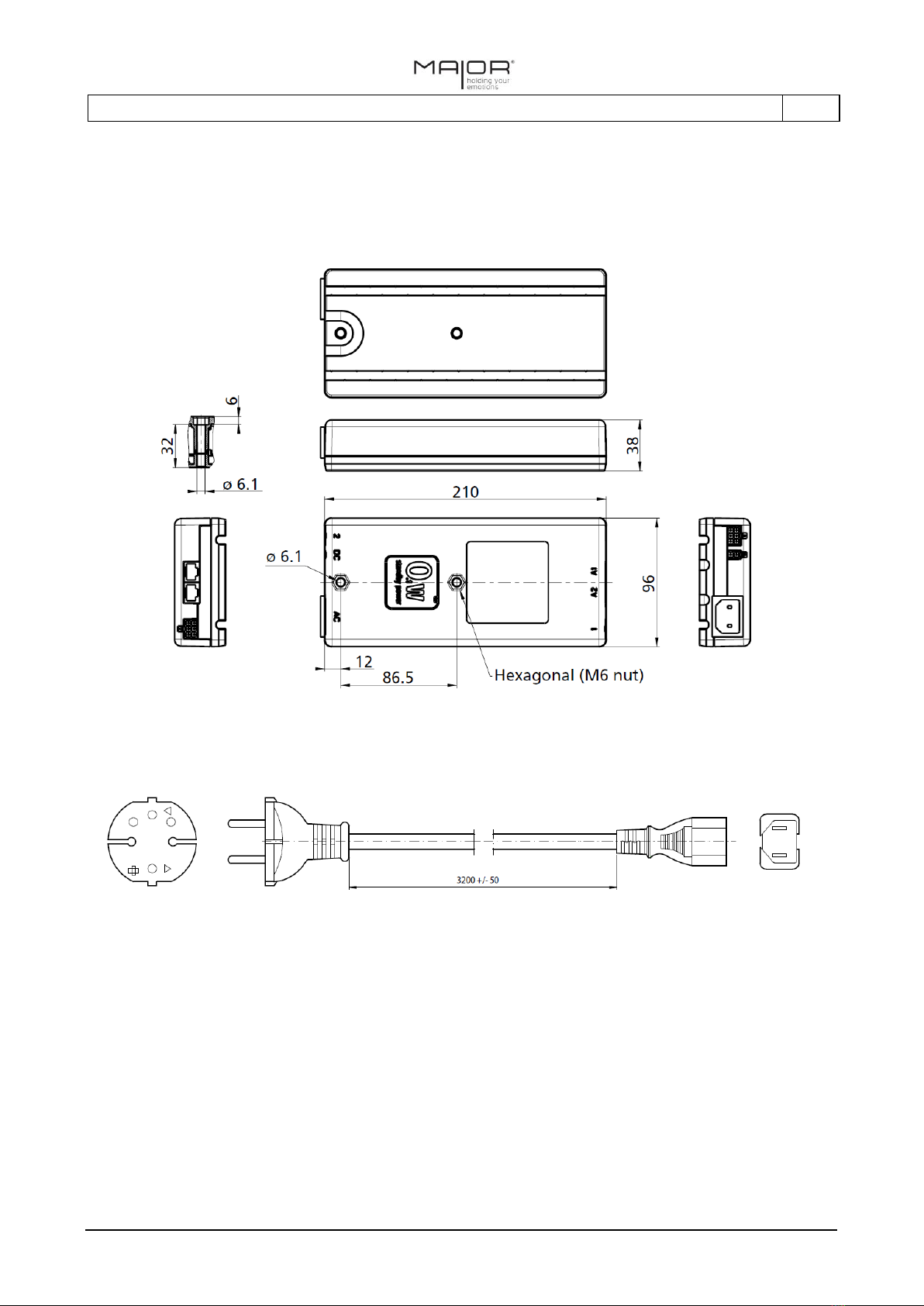
1.3.6. CDB6S unit................................................................................................................................ 9
1.3.7. Power cable compatible (EU version) ..................................................................................... 10
1.3.8. RFRL Receiver ........................................................................................................................ 10
2. Assembly instructions............................................................................................................................... 11
2.1. General safety instructions .............................................................................................................. 11
2.2. Installation........................................................................................................................................ 11
2.2.1. Instructions and tips for creating mobile.................................................................................. 11
2.2.2. installation Steps...................................................................................................................... 12
3. Operation, use, maintenance and disposal.............................................................................................. 15
3.1. Operating instructions...................................................................................................................... 15
3.2. commands ....................................................................................................................................... 15
3.3. Remote control optional................................................................................................................... 16
3.4. Procedure coupling between transmitter and receiver.................................................................... 16
3.5. Malfunction....................................................................................................................................... 17
3.6. Reset Procedure.............................................................................................................................. 17
3.6.1. Precautions.............................................................................................................................. 17
3.6.2. the column reset procedure (DL12XL) .................................................................................... 17
3.7. Maintenance .................................................................................................................................... 18
3.8. Demolition and disposal................................................................................................................... 18
4. Attached documentation........................................................................................................................... 19
4.1. EC Declaration of Conformity.......................................................................................................... 19

IT
5
1. Product
1.1. Intended uses
The equipment, called Maior Levante, is a lifting device for moving vertically a monitor or a television.
The purpose of the machine is to hide the TV, showing it only when desired.
The machine has to be installed within an article of furniture made specifically for the television that you are
going to mount. It is also envisaged that the environment in which it will be placed this mobile is not subject
to jolting movements or that may affect the cabinet and/or the machine installed in it.
The machine provides for the installation of a top closure panel that during use of the machine is moved
together with the television. This will allow to dispose, in completely closed machine, a continuous plane.
The machine can be controlled via a control panel, provided with the machine, or via its own home
automation system. It also provided an optional remote control.

IT
6
1.2. Package
The machine is attached to a pallet, packed in a wooden crate. The case is then further wrapped in a nylon
film.
The equipment must be transported using means having capacity suitable for the weight to be supported.
During transport the equipment must be protected with waterproof material to prevent seepage and water
deposits on electrical components.
1.2.1. Package Contents
Before installing the machine, check the contents of the crate.
The box contains:
- 1x machine
- 1x Drilling template
- 1x adjustable stand for top panel ⑤
- 2x decorative covers ⑧
- 2x Side cover ⑨
- 1x unit ⑫
- 1x Receiver ⑬
- Push-button 1x
- 1x Ethernet cable "linear" prepared for dry contacts and / or pushbutton (3 meters)
- 1x Instruction Manual and accompanying documents
If you verified the lack of any component, contact your dealer immediately.
1.3. Machine description
1.3.1. Components and knots
The following graphic identified the main groups and of the machine components.
Refer to it the bollinati numbers (eg. ③) present in the remainder of this manual.
Figure 1Components

IT
7
In line are some of the cables already in place, in order to cover the most common needs.
Coaxial cable 75 Ohm
Antenna
High Speed HDMI Cable
DVD, Blu-Ray, decoders
Cat.6 UTP Ethernet cable
Smart TV, data, home automation
for electric power cable of the television
The supply of cables may not correspond to that listed above in the case when ordering both a different
configuration was requested.
1.3.2. Identification of the machine
Each machine is accompanied by a label that uniquely identifies by serial number.
Figure 2: ID plate
The serial code is required for any communication relating to the machine.
The label is affixed to one of ⑧ ornamental wings, the side facing the back of the TV.
If it is necessary to consult, the wing can be removed from the machine by unscrewing the two screws that
fix it.

IT
8
1.3.3. Dimensions and technical data
Template
LEVANTE
dimensional data
Minimum height [mm]
842.5
Height [mm]
1901.5
Depth [mm]
185
maximum ascent speed [mm / s]
38
Vacuum Total weight [kg]
33
Electrical system
Power circuit [V]
220/110
Frequency [Hz]
50/60
flow
Maximum TV Capacity (including accessories) [kg]
30
Maximum TV Size
65 "900mm or until the short
side
Maximum covering panel capacity [Kg]
10
Figure 3: Dimensions
The adjustable support of the cover ⑤ panel allows an adjustment in the vertical direction,
independent of the column, 60mm

IT
9
1.3.4. Linak Actuator DL12XL
Features:
• Max. Thrust: 600 N
• Max. Speed: 38 mm / s
• Max bending moment: M max = 100 Nm dynamic
• Piezo ™: Anti-collision sensor
• PVC-Free ™
• Silent movement
use:
• Duty cycle: 5%
• Operating temperature: from + 10 ° to +40 ° C
• transport and storage temperature: -10 ° C to + 70 ° C
• approved system in accordance with EN 60335-1, UL 962 with CBD6S
Figure 4Column DL12XL
1.3.5. motor lead
Figure 5: Motor lead
The motor must be connected to the control unit via the supplied cable. The motor should not be connected
directly to the mains, it will invalidate the guarantee.
1.3.6. CDB6S unit
Features
• Power: 300W
• Power supply: 230V AC, 50Hz, or 120V AC, 60Hz
• Unit SMPS (Switch Mode Power Supply)
• Protection Electronic against overloads (EOP)
• Function soft start / stop

IT
10
• PVC-Free ™
• Power consumption in standby mode only 0.1W, ZERO ™ technology
use:
• Duty cycle: max. 10% ~ 6 minutes per hour or 2 minutes continuous use at full load
• CBD6S 300W is approved in accordance with standards EN 60335-1, EN 13849-1 and UL 962
Figure 6: Unit CDB6S
1.3.7. Power cable compatible (EU version)
Figure 7: Alimentation cable
1.3.8. RFRL Receiver
The RFR receiver operates radio frequency to 433 MHz.
It is connected to the control unit through a cable with a RJ45 connector.
The radio control operation is expected in a radius of about 6 meters from the receiver.
Environments in which there are other emitters of waves in radio-frequency, or in which the RF signal is
shielded could adversely affect the signal reception.

IT
11
2. Assembly instructions
2.1. General safety instructions
- Wear an equipment suitable to the operations to be performed, avoiding garments and accessories
that hamper the various operations or is likely to become entangled in the machine.
- Do not remove safety devices or protection.
- Any technical changes that may affect the operation or safety of Maior Levante must be carried out
only by technical personnel of the manufacturer or formally authorized by the same technicians. Do
not disassemble or special Maior Levante groups unless expressly authorized.
- Make sure that the base to which will be attached to the machine is adequate to support the weight
of the complete assembled machine Tv and any accessories, which at the limit of the data sheet can
weigh 75Kg. Otherwise, the column could go into overload, up to deteriorateand break. This could
also compromise the correct return of the cover panel in its seat, with its possible damage.
2.2. Installation
The installation of Maior Levante is closely linked to the work of the artisan who will carry out the cabinet
that contains the machine. The cabinet can be thought to be dedicated to only one slot of the TV as well as
provided with doors, drawers, shelves.
2.2.1. Instructions and tips for creating mobile
For the furniture planning no special specifications. Follow these guidelines, however, will allow optimal
performance:
- Define the final height of the cabinet according to the technical specifications of the machine.
Consider that the machine has a minimum height of 842.5 mm, and that the column can develop
maximum of 999 mm riser.
- If the mobile provides drawers, doors, shelves, it is appropriate that the compartment in which the
machine is physically isolated from the other sections of the cabinet is installed.
In order to safeguard the integrity of the machine and the TV, make sure that the space dedicated to
the machine invades any object accidentally.
- It is advisable to make provision for a removable backrest to ensure the space necessary for an
optimal installation.
- In the embodiment of the seat of the cover panel to make sure that it is not weakened the structure
of the cabinet and in particular its upper floor.
In the case of a very close installation to one of the movable end, consider to reinforce the
weakened portions of the floor taking care not to invade in any way the field of action of the
machine and taking into consideration all dimensions (eg. Ornamental wings ⑦)

IT
12
Figure 8: Mobile Example
2.2.2. installation Steps
1. Locate, using the template provided, the exact position that the machine will be within the finished
piece of furniture.
2. Install the threaded inserts (for M6 metric screws) in correspondence with the holes 6 on the
template.
3. Fasten the machine to the base by using all 6 provided screws (UNI EN ISO 10642)
4. Attach to the structure of the cabinet, where appropriate, the control unit ⑪⑫ and RF receiver.
(See Figure 8.)
5. Make the appropriate electrical connections between the various electronic components and
between the control unit and the mains. In particular:
- connect the power cable VDE 220V-110V to the control unit
- connect the RJ45 cable supplied with the RF receiver to the control unit. (Plug 0)
- plug the other end of the RJ45 cable to the RF receiver.

IT
13
- fasten the motor cable connector to the control unit. (Plug 1)
Fix the cables to the inner walls of the machine compartment so that they do not interfere in the
movement of the machine elements.
6. Testing the correct operation of the machine by acting on the remote control or on the control box.
Make sure, before you do, that there are no persons or property which could be harmed.
7. Install the adjustable support column ④ ⑤ interface by means of 4 M5 screws provided.NOn
tightening the screws, so as to facilitate the subsequent step of alignment between the cover panel
and floor.
8. The interface VESA ⑥ vertical position, and then the TV, can be adjusted by sliding the VESA ⑥
interface along the interface ④ column. In order to determine the height at which you want to fix
the VESA interface, it is necessary to evaluate the following elements:
oDistance between VESA (the TV fixing points) and bottom of the TV frame (depending on the
TV model and should therefore be measured).
oA completely closed column must remain at least 2 cm of free space between the base of
the machine and the frame ① bottom of the television or any appendices below the same
which could increase the encumbrance
1
.
oLocation of the cover panel with respect to the upper frame of the TV: adjacent to the same
or slightly spaced.
9. Loosen the 4 M6 screws that secure the VESA interface interface ⑥ ④ column. Turn the VESA
interface ⑥ preset height and tighten the screws.
10. Install the TV (screws not provided) to the VESA ⑥ using all 4 fixing points.
11. Install the cover panel. To this end the ⑤ adjustable support includes through holes 8 and 8 slots -
4 from right to left with development, 4 from front to back - which allow to cure to better centering
of the panel with respect to its seat on the floor.
Figure 9: Punctures of the adjustable support
⑤
1
In the case of the machine reset procedure (see Section 3.6) the column is closed for further 5-6 mm compared to the normal configuration and it is
necessary to leave a certain margin of safety to avoid possible collisions of the TV with the base.

IT
14
Proceed as follows:
1. Place the cover panel on adjustable support ⑤.
2. Insert screws (not supplied) into the 4 slots with development from right to left (slots-X) and
tighten loosely.
3. Adjust the left and right panel until it is centered with respect to the profiled seat on the plane.
4. Unscrew the 4 screws and insert them into the slots 4 with development from forward to
backward (Y-slots) and tighten them loosely.
5. Adjust the panel forward and backward until it is centered with respect to the contoured seat on
the plane.
6. After reaching a satisfactory configuration, secure the cover panel using the through holes 8 (Z).
Use wood screws (not supplied) appropriate to the thickness of the panel itself.
7. Adjust the height of the adjustable support ⑤ so that, in the fully closed machine, showing the
continuous plane.
12. Screw to the adjustable support ⑤ sides of the lateral coverages ⑧exploiting the provided M3
screws (supplied).
13. Carry out the necessary connections audio and video power of the TV using the cables arranged in
the catenary ⑩. Arrange the cables so they do not find obstacles during the movement of the
column and which do not impede the flow of the catenary in its collection guide⑨. In the case
where the inputs of your TV set are on the opposite side to that in which it is installed the catenary,
pass the cables between the back of the television and the column through the interface openings
VESA ⑥.
14. Among the different possibilities permitted - the column ④ interface is provided with suitable
threaded inserts - define the height at which position the ⑦ ornamental wings making sure they do
not protrude below the bottom of the television frame.
15. Fix the ⑦ ornamental wings into the holes identified by screwing each wing with 2 M6 screws
(supplied).

IT
15
3. Operation, use, maintenance and disposal
3.1. Operating instructions
For safety reasons, it is absolutely forbidden to activate the Levant commands if you do not have the vision
of the field of action of the machine. This in order to make sure there are no obstacles along the ascent
trajectory or descent of the column, and that there are no resting objects and / or teetering on the cover
panel that may fall and break or bump those who were in the vicinity of the machine.
It is forbidden to lean or exert a force on the column or on the TV.
EUROTECNO SRL accepts no responsibility for property damage and / or injury caused by failure to comply
with these instructions.
3.2. commands
Maior Levante can be controlled in two ways:
- Through panel
- By means of a home automation system.
The machine interfaces with panel and home automation system via the contacts clean.
The pushbutton is already supplied with the machine.
With regard to the configuration of the home automation system, it will be necessary to have an Ethernet
cable straight "linear" 8 pin and make appropriate connections according to the following scheme:
4 + 5 = Opening column
4 + 8 = Closing column
Control
Inputs for manual
controls / automation

IT
16
3.3. Remote control optional
In addition to the standard commands, also there is provided a remote control. The radio control is to be
understood as an optional command in that it is a control method suitable for the machine only for
environments with no radio interference.
The following are the functions associated with the remote control buttons.
Button
Drive
TO
Press and hold the button to get the screen climb.
Releasing the button stops the column in position.
If you keep the button pressed, the column stops automatically
once it reaches the maximum extension.
B
Press and hold the B button for the descent of the screen.
Releasing the button stops the column in position.
If you keep the key pressed, the column stops at the maximum
closing automatic once reached.
3.4. Procedure coupling between transmitter and receiver
The remote control which accompanies the machine in your possession has been coupled
and
tested
during assembly and is already functional.
Where it is required a new remote control or in case of replacement of the battery, it will be necessary to re-
coupling the transmitter and the receiver.
- Press the RF receiver reset button using a pen or similar and hold.
- Press the remote control button to activate it.
- Release the reset button.
Figure 11: Pairing the remote control
Figure 10: Radio

IT
17
3.5. Malfunction
If the machine may function incorrectly, see the following table.
SITUATION
CAUSE
PROCEDURE
The car does not
move.
The machine is not connected to
the electrical network.
Check the proper connection of the control
unit to the mains.
The motor cables are not
connected properly.
Check the correct connection of the motor
cables to the control unit.
The machine controls are not
connected.
Check the correct configuration of the control
methods.
The column has lost its position
control.
Make the column reset procedure (section
3.5).
The machine moves
in an irregular
manner or
discontinuously.
The motor cables are not
connected properly.
Check the correct connection of the motor
cables to the control unit.
The commands from the remote
control are not properly
interpreted by the machine.
Check the proper use of the radio control.
Check and if removing materials or sources of
interference signals within range of the radio
receiver and in the operation of the radio
(electromagnetic fields, radio waves or Wi-Fi
signals, physical barriers, shields).
The television and any accessories
installed on the machine do not
comply with the maximum flow
rate allowable weight.
Check and compare technical specifications
of the machine, television and added devices.
The door-catenary cables does
not flow regularly in its housing
Check the integrity of the catenary. Check
and remove the causes of friction. Allow
completely free from foreign bodies the
scrolling area of the catenary.
The car, arrived at a
certain point of the
descent, it stops and
goes back a few mm.
A foreign body prevents the
correct movement of the machine
and activates the protection
sensor integrated in the column.
Verify that the field of action of the car and
the television is free of any foreign body that
preclude their descent.
Remove any obstacles.
3.6. Reset Procedure
3.6.1. Precautions
In case of a reset the column will close further 5-6mm with respect to its ordinary closed configuration.
Before performing this procedure it is therefore important to verify the following:
- In the installation phase you must have been left a safety margin of 2 cm between the lower frame
of the television and the upper plane of the base ①.
- There must be no foreign objects that can be connected between the lower frame of the television
and the machine base.
- During installation, nel If it is expected a frame of abutment between the cover panel and floor, a
sufficient margin must be provided to ensure that the panel does not collide with the frame
following the reset.
3.6.2. the column reset procedure (DL12XL)
- Giving the lowering control up to complete closure of the column. No button.

IT
18
- Repeat the lowering control, keeping it for 5 seconds. The column will subside further 5-6
millimeters will then move under standard conditions. This is the signal that the reset procedure
is completed.
- If the movement is not visible, groped the complete opening of the column and then repeat the
procedure.
The reset procedure can be performed through any of the above commands.
3.7. Maintenance
The Maior Levante does not require any kind of routine or additional maintenance.
3.8. Demolition and disposal
For the demolition and disposal of the machine:
- Remove the equipment.
- Allocate the various materials that make up the disposal site within the legal framework
concerning the protection and environmental protection in force in the country where the
equipment is to be disposed.
The materials of which the machine is made are not dangerous nature; so do not require special precautions.

IT
19
4. Attached documentation
4.1. EC Declaration of Conformity
Each machine is attached its own CE compliance documentation.
Check the lamp among the documents annexed.
Table of contents
Popular TV Mount manuals by other brands

Belnick
Belnick FLASH MOUNT RA-MP003-GG quick start guide

Pioneer
Pioneer PDK-TS25 operating instructions

Gianni Industries
Gianni Industries Z-600N installation instructions

Kingfisher
Kingfisher GoodHome Rigga 5059340669366 installation instructions

Eaton
Eaton Metalux IB519014EN installation instructions

ricoo
ricoo ENZ CZ0900 Assembly instructions