Major Manufacturing HIT-66-274 User manual

INSTRUCTIONS
FOR
HIT-66-274 TEMPLATE
FOR
SARGENT “IN” SERIES
CYLINDRICAL LOCK
1825 VIA BURTON
ANAHEIM CA 92806
714-772-5202 / FAX 714-772-2302
WEB: WWW.MAJORMFG.COM
WHEN USING POWER TOOLS
ALWAYS WEAR
EYE AND EAR PROTECTION!!

THINK
SAFETY!!
WHEN USING POWER TOOLS
ALWAYS WEAR
EYE PROTECTION!!
Before attempting any installation know
how to safely use the power tools involved.
Be sure all bits and cutters are sharp and
in good condition and all power tools and
extension cords are in good working order
and properly grounded. AND MOST
IMPORTANTLY, BE SURE TO WEAR,
EYE AND EAR PROTECTION.
PAGE 1
Copyright 2016—Major Manufacturing

All hole saws are not created equal. A
cheap hole saw from a home improvement
center or one that has been dropped can
be out of round and will not fit the drill
bushings in our templates. When using
hole saws, pull the hole saw out of the cut
frequently to clear chips.
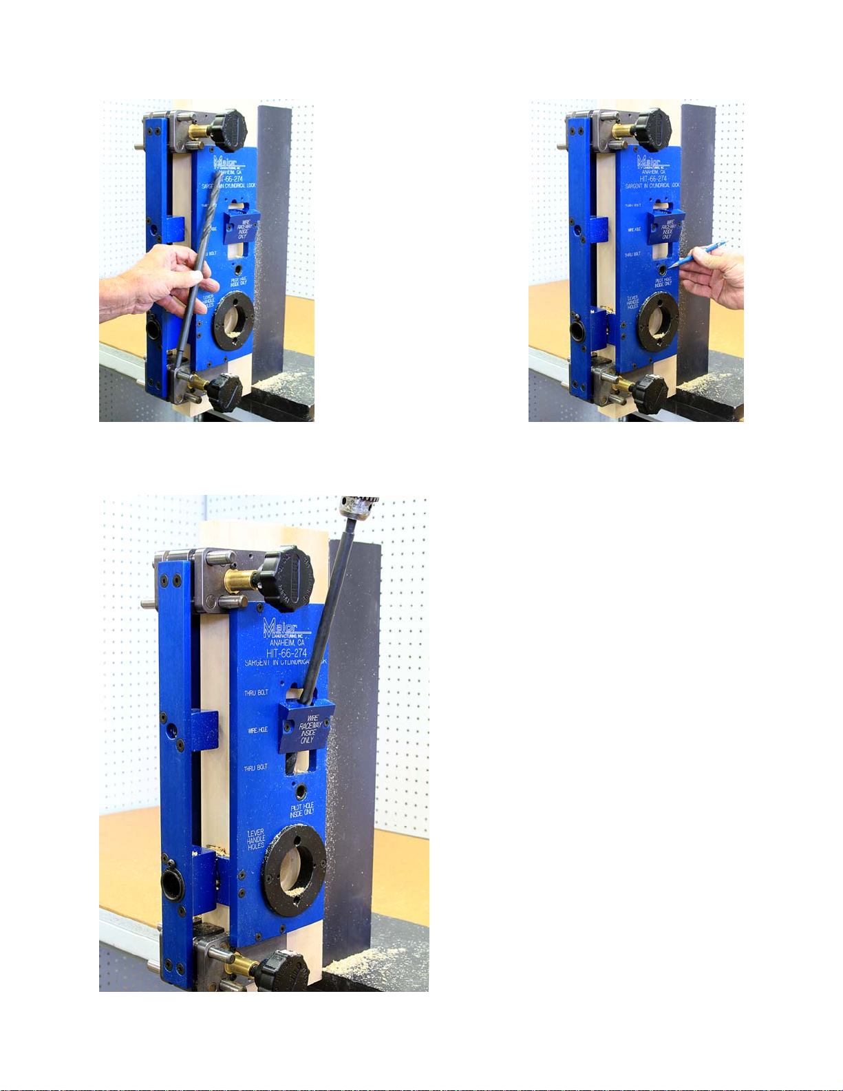
Shown above is a standard twist drill
bit. They can be used on both wood or
steel doors. Be sure to back out the bit
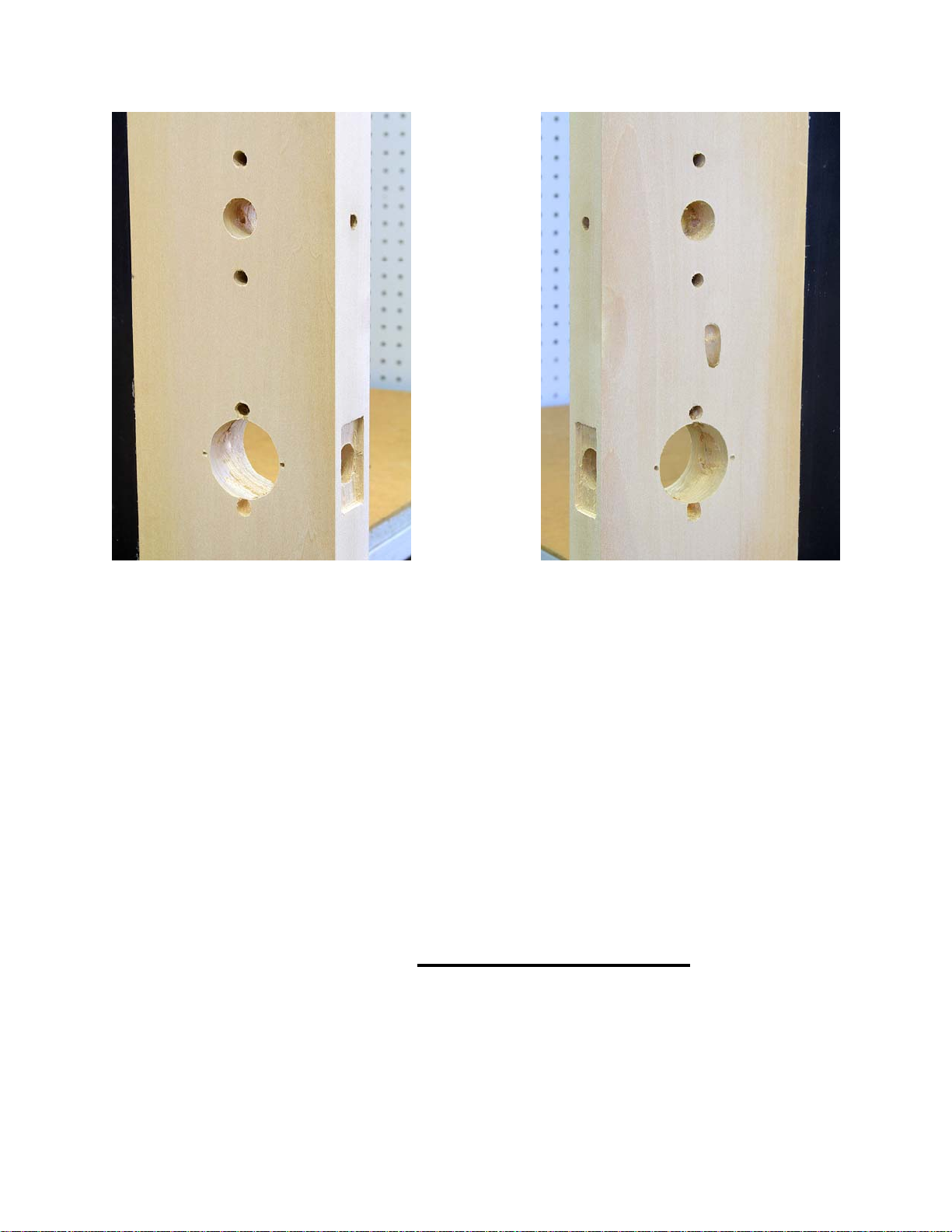
when drilling to clear chips. Shown above and at right is
a brad point bit. They will
produce a very clean hole in
a wood door. Use at a low
speed and back the bit out
to clear chips. Do not use
on a steel door.
Shown above is a spade or paddle type
bit. Do not attempt to use this in any
drill guide. There is no bearing surface
and you will jam the bit.
Shown above is a tri-flute drill bit. Do
not attempt to use this in a drill guide.
The lack of bearing surface will cause
the bit to jam.
Drill Bit Types
PAGE 2
Copyright 2016—Major Manufacturing

With both clamps opened equally,
install both inside and outside
templates to the HIT-66 clamp as
shown. Do not tighten the 10-32
screws at this time. When all
screws have been loosely
installed, then it is ok to tighten.
Install the “U” shaped alignment
guide to either side of the
template set. This is used to
align the template with the
cylindrical latch when retrofitting.
PAGE 3
Copyright 2016—Major Manufacturing Inc
NOTE: The HIT-66 clamps
shown are not part of the
HIT-66-274 template set and
must be purchased as a
separate item.
Install the drill guide for latch and
optional external DPS to the front of
the HIT-66 clamps as shown. Do not
tighten the 1/4-20 screws at this time.
When all screws have been loosely
installed, then it is ok to tighten.

Shown at left is a standard 1-
3/4” lock mount. We will use
this as a basis for the
Sargent IN Cylindrical Lock
install.
lock.
PAGE 4
Copyright 2016—Major Manufacturing Inc
The HIT-66-274 can be used to do a new
install on a blank door, as above, or retro fit
an existing cylindrical prep as shown at left.
If doing a new install the jig clamps to the
door at the desired height and is ready to go.
If doing a retro fit follow the next couple of
steps.
Insert the blue alignment plug ( supplied) into
the latch cross bore.

With a 5/32” twist drill,
drill the holes for
anchor lugs using the
holes located at 3:00
and 9:00 positions.
Drill about 3/16” into a
wood door. On a steel
door you may need to
open the hole into a
notch with the use of
a file prior to installing
the lock.
Slide the HIT-66 clamp
system onto the door
with the “U” shaped
guide over the blue
alignment plug. Tighten
the clamps by alternat-
ing between the top
and bottom clamp. Do
not tighten one clamp
all the way at once.
Start by drilling the
two post holes with a
7/16” twist drill. Drill
half way from both
sides of the door. If
this is a retro fit it is a
good idea to re-drill
these holes if they
are on the door. This
will ensure they are
straight and true.
PAGE 5
Copyright 2016
Major Manufacturing Inc
PAGE 5

Using a 1” auger or brad point bit,
drill the latch hole. Pull the bit out of
the hole several times when drilling
to remove a chips.
PAGE 6
With a 2-1/8” hole
saw, drill the cross
bore hole. Drill from
both sides of the
door. When drilling,
back the hole saw
out of the cut to
remove chips.
With a 3/8” twist drill,
drill the holes for the
thru bolts. Drill top
and bottom holes
half way from both
sides of the door.
Pull drill out several
times when drilling to
remove chips.
Copyright 2016
Major Manufacturing Inc

Use a 1” hole saw
and drill the wire
hole. Drill this hole
half way from both
sides of the door.
Back the hole saw
out once or twice
when drilling to clear
the chips from the
cut.
PAGE 7
If installing the
optional external
DPS, drill this hole
with a 3/8” drill bit to
the wire chase hole.
Be sure to back the
drill bit all the way out
of the guide to clear
chips. This will require
a longer than normal
drill bit. If installing on
a steel door, increase
the 3/8” hole to 3/4”
with the use of a step
drill.
To drill the wire
raceway, remove the
drill plate on the
INSIDE of the door
and replace with the
auxiliary raceway drill
guide.
Copyright 2016
Major Manufacturing Inc
PAGE 7

The wire raceway will
also require a longer
than normal drill bit.
This is a 1/2”
diameter bit 12 inches
long.
Shown at right is a
pilot hole for the bit
which is only drilled
1/2” deep into the
door, not all the way
through.
Drill the raceway hole to
the cross bore. The drill bit
must be pulled completely
out of the drill bushing
when drilling to clear chips.
This is important when
drilling this deep of a hole.
Copyright 2016
Major Manufacturing Inc
PAGE 8

Visit our web site at www.majormfg.com for more
information on lock templates and a complete listing
of all the tools we have available. While there, sign up
for our newsletter and we will email new product
information directly to you.
Completed installation
That’s all there is to it!
Copyright 2016—Major Manufacturing Inc
Outside Inside
PAGE 9
Table of contents