Major tech MTi15 User manual

INSTRUCTION MANUAL
160 x 120 Pixels
Thermal Imager
MTi15

2

Contents Page no
1. Introduction......................................................................................5
2. Safety Information............................................................................5
3. Packing Lists....................................................................................6
4. Specifications...................................................................................7
5. Structural Description......................................................................9
6. Before you start.............................................................................10
6.1 How to charge the battery....................................................10
6.2 Power On.............................................................................10
6.3 Power Off.............................................................................11
6.4 Desktop................................................................................11
6.5 Lens..................................................................................... 12
6.6 Focus.....................................................................................13
6.7 Shutter...................................................................................13
6.8 Temperature Measurement.......................................................13
6.9 Emissitivity Adjustment............................................................14
6.10 Reflective Temperature.............................................................14
6.11 Thermal Imager Reporter Software............................................15
7. Menus............................................................................................15
7.1 Main Menu...........................................................................15
7.2 Image Mode.........................................................................16
7.3 Image Palette.......................................................................18
7.4 Image Adjustment................................................................19
7.4.1 Lock Operation...........................................................19
7.4.2 Histogram Mode and Auto Mode................................20
7.5 Measurement Menu............................................................21
7.6 Parameter Menu..................................................................21
7.6.1 Ambient Temperature Composation.........................22
7.6.2 Reflective Temperature.............................................22
7.6.3 Atmospheric Humidity...............................................22
7.6.4 Delta Temperature Compensation............................23
7.6.5 Distance....................................................................23
7.6.6 Emissivity..................................................................23

Contents Page no
7.7 Settings Menu......................................................................24
7.7.1 Device Settings.........................................................24
7.7.2 Measure Settings......................................................26
7.7.3 Reset.........................................................................27
7.8 Camera Menu.....................................................................28
7.8.1 Save Image...............................................................28
7.8.2 Add Text Note............................................................29
7.8.3 Change Measure Parameters..................................29
7.8.4 Add Analyse Tools.....................................................29
7.8.5 Change Image Mode................................................29
7.8.6 Change Colour..........................................................30
7.9 Video Menu........................................................................30
7.10 Files Browser.......................................................................30
7.10.1 Analyse an Image....................................................30
7.10.2 Play a Video.............................................................31
7.10.3 View Image Info......................................................31
7.10.4 Delete File...............................................................31
7.11 USB Mode..............................................................................31
8. Fault Diagnosis and Exclusion.......................................................32
9. Android/iOS APP Thermview.........................................................32
9.1 Software Install and Uninstall.................................................32
9.1.1 System Required...........................................................32
9.1.2 Thermview App Install...................................................32
9.2 Thermview Function...............................................................32
9.2.1 Import Pictures..............................................................32
9.2.2 Analyse..........................................................................33
9.2.3 Report and Share..........................................................34
10. PC Software.................................................................................35
10.1 System Required.................................................................35
10.2 IR Meter Install....................................................................35
10.3 Running.............................................................................. 35
10.4 Uninstall..............................................................................35

1. lntroduction
• The Thermal lmager is a hand held imaging camera used for predictive
maintenance, equipment troubleshooting and verification.
• Focus the lens to the object, then the thermal and visual images are
displayed on the LCD and can be saved to a Micro SD Memory card.
• Transferring images to a PC is accomplished by removing the SD memory
card and connecting it to a PC through a card reader (not included), or
transfer the images and video stream to the smart device with
"Thermoview" apps installed.
• In addition to the features mentioned above, the Thermal lmager
provides video recording and play back
5
1. Safety Information
• To prevent eye damage and personal injury, do not look into the laser. Do
not point the laser directly at people or animals or indirectly off reflective
surfaces.
• Do not disassemble or do a modification to the Thermal Imager.
• Do not point the Thermal Imager (with or without the lens cover) at
intensive energy sources, for example devices that emit laser radiation, or
the sun.
• This can have an unwanted effect on the accuracy of the camera. It can
also cause damage to the detector in the Thermal Imager.
• Do not use the Thermal Imager in a temperature higher than 50°C
(122°F), lower than -20°C (-4°F), High temperature or low temperature
can cause damage to the Thermal Imager.
• Only use the correct equipment to discharge the battery.
• If you do not use the correct equipment, you can decrease the
performance or the life cycle of the battery. If you do not use the correct
equipment, an incorrect flow of current to the battery can occur. This can
cause the battery to become hot, or cause an explosion and injure the
user.
• Do not pull out the battery when the thermal imager is working.
• If you pull out the battery when the thermal imager is working, it may
cause the thermal imager to work erroneously.
• Do not disassemble or do a modification to the battery.
• The battery contains safety and protection devices which, if they become
damaged, can cause the battery to become hot, or cause an explosion or
an ignition.
• If there is a leak from the battery and the fluid gets into your eyes, do
not rub your eyes. Flush well with water and immediately get medical
care.

6
• Do not make holes in the battery with objects. Do not hit the battery with
a hammer. Do not step on the battery, or apply strong impacts or shocks
to it.
• Do not put the battery in or near a fire, or in direct sunlight, or other
high-temperature locations. Do not solder directly onto the battery.
• Always charge the battery in the specified temperature range.
• The temperature range through which you can charge the battery is 0 to
50°C (32 to 122°F). If you charge the battery at temperatures out of this
range, it can cause the battery to become hot or to break, It can also
decrease the performance or the life cycle of the battery.
• Do not get water or salt water on the battery, or permit the battery to get
wet.
• Clean the case with a damp cloth and a weak soap solution. Do not use
abrasives, isopropyl alcohol, or solvents to clean the case or lens/screen.
• Be careful when you clean the infrared lens. Do not clean the infrared
lens too vigorously, This can damage the anti-reflective coating.
• Taking the Thermal Imager from cold to hot may cause condensation in
the thermal Imager. To protect the Thermal Imager, you should switch off
the Thermal Imager, wait until the Thermal Imager has become warm
enough for the condensation to evaporate.
• If you do not use the Thermal Imager, put the Thermal Imager in cool
and dry environment. If you store the Thermal Imager with the battery
inserted, the power of the battery will be depleted.
3.Packing Lists
Item Quantity Description
Thermal lmager 1
Lens 1 Field of View=20.7°x 15.6°, f=7.5mm
Li-ion Battery 1 3.7V, 2600mAH
AC Adaptor 1 Input AC Volts: 100V-240V, 50/60Hz,
MAX 0.9A; Output DC Volts: 5V,
2400mA
Micro SD 1 8Gbyt
USB Cable 1
Non-Slip Strap 1
User Manual 1
Warranty Card 1
PC Software Installation CD 1
Carrying Case 1

Imaging and Optical Data
Field of View(FOV)/Minimum
Focus Distance 20.7°x 15.6°/0.5m
Spatial Resolution(IFOV) 2.26mrad
Thermal Sensitivity/NETD <0.05°C at 30°C (86°F) / 50mK
Image Frequency 50Hz
Focus Mode Manual
Zoom 1-16x continuous, digital zoom
Focal Length 7.5mm
Focal Plane Array(FPA)/Spectral
Range Uncooled microbolometer / 8-14μm
IR Resolution 160 x 120 pixels
Image Presentation
Display 3.5in. LCD, 640x480 pixels, Touch
screen
Image Modes IR image, Visual image, Picture in
picture, Auto fusion, zoom.
Color Palettes IRON, Rainbow, Grey, Grey Inverted,
Brown, Blue-red, Hot-cold, Feather,
Above alarm, Below alarm, Zone
alarm, Vision zone.
Measurement
Object Temperature Range -20 to 150°C (-4 to 302°F) /
0 to 650°C (32 to 1202°F)
Temperature Accuracy ±2°C (3.6°F) or ±2% of reading
(Environment temperature 10 to
35°C, Object temperature >0°C)
Measurement Analysis
Spot Center Spot, Three manual spots
Automatic Hot/Cold Detection Auto hot or cold markers
Line Two lines analyse
Area Three areas analyse
Measurement Corrections Emissivity, Reflected temperature
Storage of Videos
Storage Media 8GB Micro SD card or 3.4GB internal
EMMC
Video Storage Format Standard MPEG-4 encode, 640x480 at
30fps, on memory card >60 minutes
Video Storage Mode IR/visual images; simultaneous
storage of IR and visual images
4. Specifications
7
Function Range

8
Function Range
Storage of Images
Image Storage Format Standard JPEG, or HIR files including
measurement data, on memory card
>6000 pictures
Image Storage Mode IR/visual images; simultaneous
storage of IR and visual images
Image Analyse Internal image analyse tools.
Complete function
Set-Up
Set-up commands Local adaptation of units, language,
date and time formats, information of
camera
Languages Multinational
Digital Camera
Built-in Digital Camera 2 Megapixels
Built-in Digital Lens Data FOV 65°
Data Communication Interfaces
Interfaces USB-Type C
USB Data transform between camera and
PC; Live video between camera & PC
Wifi 802.11, transfer images and realtime
video stream
Power System
Battery Li-ion battery, 4 hours operating time
Input Voltage DC 5V
Charging System In camera (AC adapter)
Power Management Automatic shutdown
Environmental Data
Operating Temperature Range -15 to 50°C (5 to 122°F)
Storage Temperature Range -40 to 70°C (-40 to 158°F)
Humidity (Operating and Storage) 10% to 90%
Drop Test 2m
Bump 25g (I EC60068-2-29)
Vibration 2g (IEC60068-2-6)
Physical Data
Camera Weight. Incl. Battery <500g
Camera Size (L x W x H) 224 x 77 x 96mm
4. Specifications Continued
7
9
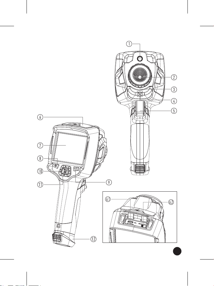
5. Structure Description
1 - Visual Camera
2 - lnfrared Camera Lens
3 - Focus Ring
4 - Dust Cover Lanyard Hole
5 - Trigger
6 - lnterface and Cover
6.1 - Type-C USB/Charge
6.2 - Micro SD Card Slot
7 - LCD Display and Touch Screen
8 - lmages Browse Button
9 - Power/Lock Button
10 - Menu/Select Button
11 - Up/Down/Right/Left Button
12 - Battery
6. Before You Start
6.1. How to Charge the Battery
• Before you use the Thermal Imager for the first time, charge the battery
for three and a half hours.
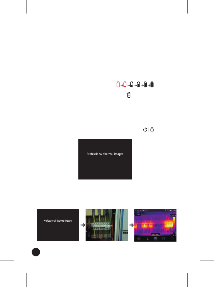
• The battery status shows on the six-segment charge indicator.
• To charge the battery, use follow before:
1. Connect the ac power adapter into an AC wall outlet and connect the
DC output to the Thermal Imager’s AC power socket. The charge light
is on, The battery indicator becomes " " while the
battery charges with the AC power adapter.
2. Charge until the charge indicator becomes " " the charge icon will not
change.
3. Disconnect AC power adapter when the battery is fully charged.
Note: Make sure that the Thermal Imager is near room temperature before
you connect it to the charger. Do not charge in hot or cold areas. When you
charge in extreme temperature, battery capacity may be damaged.
6.2. Power On
To turn the Thermal Imager on, push the Power/Lock " " Button for
about 2 seconds.
Note: After turning on the device, the thermal Imager needs sufficient
warm-up time for the most accurate temperature measurements and best
image quality. So the visible image will first appear, and the thermal sensor
will calibrate internal for several seconds. After that the thermal image will
be displayed on the screen.
10
Table of contents
Other Major tech Laboratory Equipment manuals

Popular Laboratory Equipment manuals by other brands


Agilent Technologies
Agilent Technologies 5800 ICP-OES user guide

Endress+Hauser
Endress+Hauser Cleanfit CPA875 operating instructions

NI
NI PXI-5422 CALIBRATION PROCEDURE

Collomix
Collomix Aqix operating instructions

SPEX SamplePrep
SPEX SamplePrep 6875 Freezer/Mill Series operating manual

Ocean Insight
Ocean Insight FLAME-NIR+ Installation and operation manual

Parker
Parker ALIGN-MG-NA Installation, operation and maintenance manual

BD
BD 644787 user guide

DENTAURUM
DENTAURUM Compact Megaplus Instructions for use

Biuged Laboratory Instruments
Biuged Laboratory Instruments BGD 626 instruction manual

VWR
VWR SAS Super IAQ instruction manual

illumina
illumina MiSeqDx reference guide