Major Maxi 4 PSU User manual

Power Supply Unit (PSU)
Maxi PSU / Micro PSU
Manual

Version:
1.0
Issued: 04.12.2015
© 2015
Copyright by Lightpower GmbH
ithout having any written permission from the editor it is not
allowed to copy, reproduce or publish any part of this manaul,
neither in printed form nor by photos or electronic media.
All technical
specifications are subject to change without
Notification.
Contact, service and support Germany und Europe:
Lightpower GmbH
An der Talle 24
– 28
33102 Paderborn
Telefon: +49. 5251. 1432-20
Fax: +49. 5251. 1432-80
E-Mail: info@lightpower.de
eb: www.lightpower.de

Version: 2.0, 18.11.2011 3
General
No matter if fixed installation or touring business – complex lighting s stems alwa s
require best reliabilit together with relativel eas operation and maintenance
features. In order to be able to solve eventuall occurring problems not onl fast but
also most efficientl , it is important to know which component of the s stem fulfils
which purpose.
This fact has been taken into consideration during the design and development of
Rainbow Colour Changers. And this is wh we find the entire “intelligence” where we
first expect it to be: within the Colour Changers themselves, but not in the power
suppl unit. Consequentl the DMX-addressing, the selection of channels, etc... is
done right on the Colour Changer itself.
The external power suppl unit (PSU) combines the DMX signal with the internal 24 V
DC of the Colour Changer. These power/control signals are available on the female
XLR4 outputs.
Different versions
In order to meet our individual demands, we offer two different PSU-versions:
the MICRO PSU with 1 output is able to run up to 6 Colour Changers
the MAXI PSU with 4 outputs can run up to 24 units
The maximum number of Colour Changers per output is restricted:
PSU
ma
x. no. of
units (altogether)
max. no. of 6”, 8”,
12” per output
max. no. of 15”,
8- ite per output
Micro 6 6 3
Maxi 24 12 6
Power Supply
The Micro PSU as well as the Maxi PSU are connected with the mains via powerCON
connection. The necessar operating voltage of the Colour Changers (24 V) is
guaranteed b the opto-isolated, overload-protected power suppl .
The PSUs adjusts itself automaticall to the operating voltage from 100 to 240 Volt.

4 Version: 2.0, 18.11.2011
DMX Input / Output
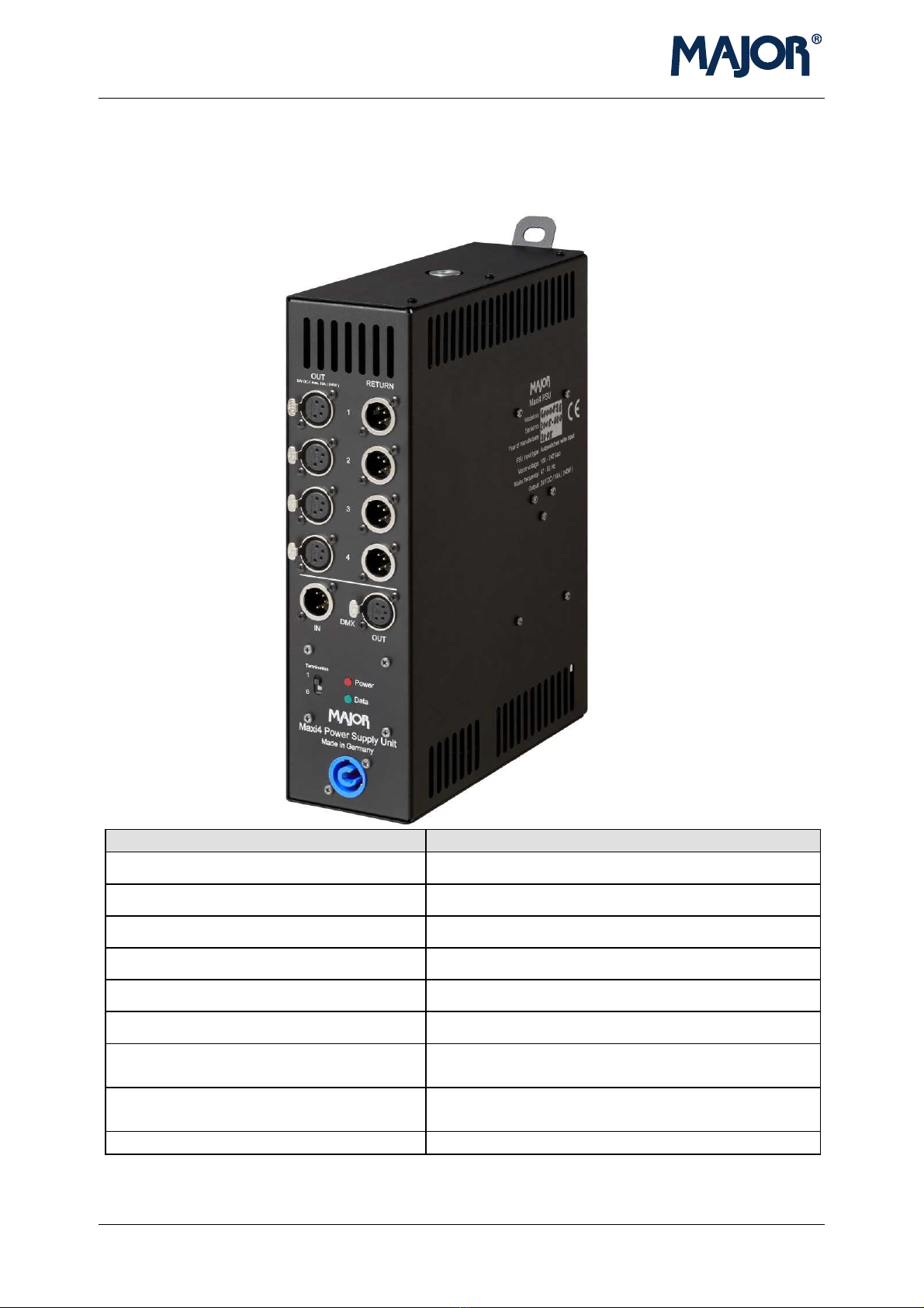
The control signal (DMX) is fed through the XLR5pol. male socket. The DMX output is
a “feed through” output, which means that the DMX signal will be dais -chained and
will also be available on the output in case of a power failure. Major PSUs are
designed to put minimum strain on the DMX signal.
Termination
If the Major PSU is the last unit in line (of DMX cabling), the DMX signal must be ter-
minated. Therefore ou will find a termination switch on the unit.
If the termination switch is set to ON, the Micro PSU indicates this b the ellow LED
and the MAXI PSU b the flashing red LED.
Output / Return sockets
In order to protect the main DMX signal against negative influences caused b defec-
tive cabling, etc..., it is galvanicall separated from the Colour Changer outputs via
opto-isolated coupling inside the PSU.
The outputs to the scrollers are designed as XLR4pol. sockets, which are connected
with the XLR4pol. male socket of the first Colour Changer in line via Major Power/Data
cables. Further scrollers are connected from the XLR4pol. female socket of the first
Colour Changer in line to the second one, etc...
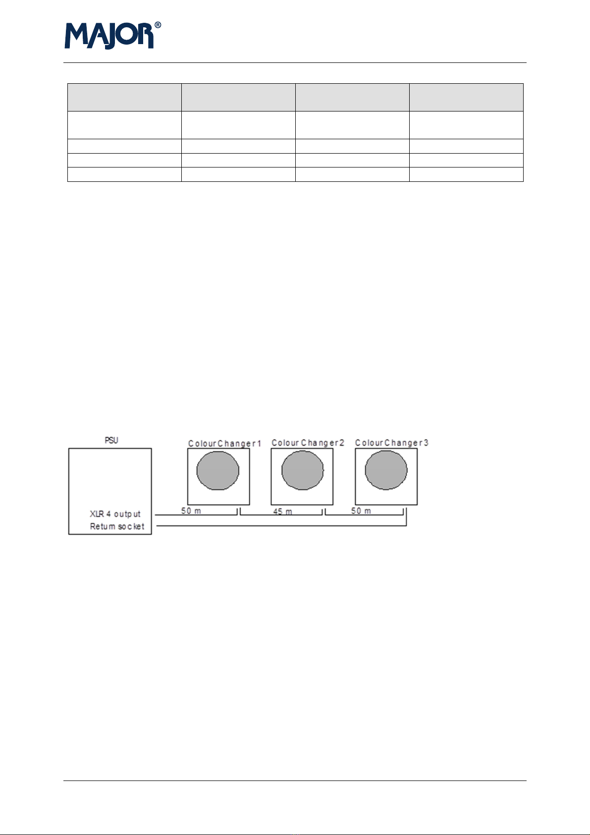
In order to improve current feeding and DMX transmission, we alwa s recommend to
connect a so-called return cable from the last scroller on each output back to the PSU
return socket (XLR4pol. male). This wa the suppl voltage will be led back again to
the Colour Changer – in parallel to the output. Via an internal termination resistor the
loop cabling is automaticall terminated when connecting the return cable.
Protection
Each PSU output is internall protected. The fuse on the PCB inside the Micro PSU is
able to put itself back.
Inside the Maxi PSU ou will find so-called “Pico Fuses”, which are located on the
PCB. These fuses protect the PCB against damages, which might be caused b
incorrectl assigned or defective scroller cables.
Pin assignment

Version: 2.0, 18.11.2011 5
DMX 512 (1990)
XLR 5 pol
Colour Changer
signal cable
XLR4 pol
Pin 1: Ground (Screen) Pin 1: 0 V; Ground
Pin 2: Data - Pin 2: Data-
Pin 3: Data + Pin 3: Data+
Pin : 2 V +
Power/Data cable
In order to guarantee a reliable operation, we strongly recommend the use of our Major
Power/Data cable. This XLR pole cable contains two lines á 0,38 mm² for the
transmission of the DMX signals, as well as two lines à 2,08 mm² for the supply
voltage of the Colour Changers.
The high cross-section of the live wired lines considerably increases the maximum
cable length, which you can use within the system. In order to ensure a reliable
operation, you should not use more than 300 m total cable length (theoretical figure)
per output. Please note that you have to differentiate between the theoretical cable
length and the actually usable cable length.
Example:
1. Actually usable cable length: 1 5 m (see systemdrawing)
2. Theoretical cable length: 290 m (please see calculation chart below):
Colour Changer no. 1 = 50 m = 50 m
Colour Changer no. 2 = 50 m + 5 m = 95 m
Colour Changer no. 3 = 50 m + 5 m +50 m = 1 5 m
Total theoretical cable length in this drawing = 290 m
(You have to add the total cable length between each Colour Changer and the PSU in
order to calculate the theoretical figure.)

6 Version: 2.0, 18.11.2011
ontrol-displays
The Maxi PSU has 2 control LEDs, which are situated on the same side as the
sockets:
The red LED shining permanent indicates that the 24 V DC suppl is OK.
When the “termination“-switch is activated, the red LED is flashing.
The green LED indicates that a DMX signal is present at the XLR5pol. input.
The Micro PSU has three LEDs:
The ellow LED indicates that the “termination“-switch is activated.
The red LED shows, if the 24 V DC suppl is OK.
The green LED indicates that a DMX signal is present at the XLR5pol. input.

Version: 2.0, 18.11.2011 7
Specification Micro PSU
Technical data Micro PSU
4000897
B x H x T (in mm) 136x178x72
Weight 1.37 kg / 3 lbs
Connectors – Out to scrollers XLR - 4 pin - F
Connectors – Return from scroller XLR - 4 pin - M
Connector – DMX512 input XLR - 5 pin - M
Connector – DMX512 output XLR - 5 pin - F
Opto-isolated DMX512 input, low load
Yes
Switch for termination of the DMX512
input
Yes
Connector – Mains powerCON blue
Mains input 100-240V Volt AC Standard
Max. number of units (altogether) 6 x 6”, 8”, 12” PRO or 3 x 15”, 8-Lite PRO
Max. number of scroller per output 6 x 6”, 8”, 12” PRO or 3 x 15”, 8-Lite PRO
CE approval 2006/95/EG (Niederspannungsrichtlinie)
2004/108/EG (Elektromagnetische
Verträglichkeit)
EN 60204-1 (Sicherheit von Maschinen)
Protection class I
Accessories 210474 Schukocable
280178-1 Saveking

8 Version: 2.0, 18.11.2011
Specification Maxi PSU
Technical data
Maxi PSU
4000896
B x H x T (in mm) 82 x 293 x 250
Weight 3.3 kg / 7.3 lbs
Connectors – Out to scrollers XLR - 4 pin - F
Connectors – Return from scroller XLR - 4 pin - M
Connector – DMX512 input XLR - 5 pin - M
Connector – DMX512 output XLR - 5 pin - F
Opto-isolated DMX512 input, low
load
Yes
Switch for termination of the DMX512
input
Yes
Connector – Mains Standard

Version: 2.0, 18.11.2011 9
Max. number of units (altogether) 24 x 6”, 8”, 12” PRO or 12 x 15”, 8-Lite PRO
Max. number of scroller per output 12 x 6”, 8”, 12” PRO or 6 x 15”, 8-Lite PRO
CE approval 2006/95/EG (Niederspannungsrichtlinie)
2004/108/EG (Elektromagnetische
Verträglichkeit)
EN 60204-1 (Sicherheit von Maschinen)
Protection class I
Accessories 210474 Schukocable
280178-1 Saveking

10 Version: 2.0, 18.11.2011
This manual suits for next models
3
Table of contents