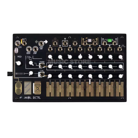
Make Noise DPO User manual

©2015 - Compiled by Robert Anselmi Reason101.net Visit www.makenoisemusic.com for full manual
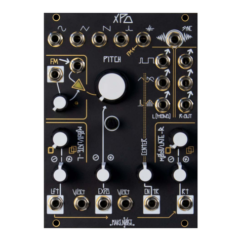
Make Noise DPO Complex Dual VCO Module
The DPO is a dual VCO designed for generating complex waveforms and implementing FM synthesis in the analog domain. Expanding on the classic arrange-
ment of primary and mod oscillators, the DPO has both of the VCOs operable as complex signal sources. It is, in essence, a Dual Primary Oscillator. Dynamic
FM, Circular FM, Hard Sync and Additive Harmonic synthesis processes are all achieved with internal routing on the DPO. The DPO has two modulation buses
(Mod & FM), each with multiple destinations, the depth of which is adjustable per destination. The DPO is a 100% analog, vintage voiced musical instrument.
OSCILLATOR
A WAVEFORM
OUTS: Triangle
wave output.
10Vpp. Sawtooth
wave output.
9Vpp. Sine wave
output. 10Vpp.
SHAPE ROTARY, SHAPE CV IN & ATEN-
UATOR: The Shape Rotary is a unipolar control
that determines the shape of the waveform feed-
ing the Fold circuit. Morphs from Sine to Spike to
Glitched Triangle. The Shape CV In is a unipolar
control signal input normalled into the Mod Bus.
Range: 0V to +5V. The Shape Attenuator is a
unipolar level control for the Shape CV Input.
OSCILLATOR B
WAVEFORM OUTS:
Sine wave output.
10Vpp. Square wave
output. 9Vpp. Final wave
output is processed by
the Shape, Angle & Fold
circuits. 10Vpp.
ANGLE ROTARY, AN-
GLE CV IN & ATTENU-
ATOR: The Angle Rotary
tilts the added harmonics to
either end of the wave-cycle.
The Angle CV In is a bipolar
control signal input normalled
into the Mod Bus. Range: 8V.
The Angle Attenuator is a
unipolar level control for the
Angle CV Input.
FOLD ROTARY, FOLD
CV IN, FOLD ATTENU-
ATOR & STRIKE GATE IN: The Fold Rotary
is a unipolar control that continuously varies the
low-order harmonics of the signal by folding the
waveform into itself. Fold CV In is a unipolar control
signal input normalled into the Mod Bus. Fold At-
tenuator is a unipolar level control for the Fold CV
Input. The Strike Gate In, when patched, briey
opens the Fold circuit to 100%. Requires an 8V -
10V gate or clock to operate.
VCO A COARSE TUNE RO-
TARY: Controls coarse tuning for
oscillator A frequency. Range: 9.5
octaves; 12hz-6khz.
VCO B COARSE TUNE
ROTARY & VCO B 1V/
OCT SCALE TRIM: Con-
trols coarse tuning for oscil-
lator B frequency. Range: 9.5
octaves; 12hz-6khz. The 1V/
Octave Scale Trim control is
used to calibrate VCO B.
VCO A FINE TUNE ROTARY:
Controls ne tuning for oscillator A
frequency. Range: 1.75 octaves.
VCO B FINE TUNE RO-
TARY: Controls ne tuning
for oscillator B frequency.
Range: 1.75 octaves.
VCO A 1V/OCT SCALE TRIM:
Used to calibrate VCO A.
VCO A 1V/OCTAVE CV IN:
Bipolar pitch control for VCO A.
Optimal range: +/-5V.
VCO B 1V/
OCTAVE CV IN:
Bipolar pitch control
for VCO B. Optimal
range: +/-5V.
VCO A EXPONENTIAL CV IN
& ATTENUATOR: Bipolar expo-
nential frequency CV input for VCO
A. Normalled to FM Bus. Range:
10V. The associated Exponential
Attenuator acts as a unipolar level
control for the Exponential CV Input.
VCO B EXPONENTIAL CV IN & ATTENUATOR: Bipolar exponen-
tial frequency CV input for VCO B. Normalled to FM Bus. Range: 10V. The
Exponential Attenuator acts as a unipolar level control for the CV Input.
MOD BUS INDEX ROTARY, EXTERNAL SOURCE IN,
INDEX IN, ATTENUVERTOR & LED: The Mod Bus Index
Rotary is a unipolar control that sets the depth of the Mod Bus.
The Mod Bus External Source Input interrupts internal routing
of VCO A sine wave as a modulation source. Range: +/- 8V. The
Mod Bus Index CV Input is a bipolar CV input signal. Range:
+/- 4V. The associated Mod Bus Index Attenuvertor acts as a
bipolar level control for the Mod Bus Index CV Input. The Mod
Bus Index LED provides visual indication of the currently pro-
grammed Mod Index value.
FM BUS ROTARY, INDEX CV IN, ATTENUVER-
TOR & LED: The FM Bus Rotary is a unipolar control
that sets the depth of the FM. The FM Bus Index CV Input
is a bipolar CV input. Range: +/-4V. The FM Bus Index
Attenuvertor acts as a bipolar level control for the FM Bus
Index CV Input. The FM Bus Index LED provides visual
indication of the currently programmed FM Index value.
FOLLOW CV IN & ATTENU-
ATOR: The Follow CV Input is a
unipolar control. Range: 0V to 5V. The
Follow Attenuator determines how
well VCO A follows VCO B. With noth-
ing patched to Follow CV In, it acts as
a standard control. When patched, it
acts as an attenuator for that signal.
BEAT FRE-
QUENCY
LED: Provides
visual indication
of the phase
difference
between VCOs
A & B.
VCO A LINEAR CV IN & ATTENUATOR:
Unipolar linear frequency CV input for VCO A.
AC coupled. Normalled to FM Bus. Range: 10V.
The associated Linear Attenuator acts as a
unipolar level control for the Linear CV Input.
VCO B LINEAR CV IN, LINEAR ATTENUATOR & EXTERNAL LOCK
IN: Unipolar linear frequency CV input for VCO B. AC coupled. Normalled to FM
Bus. Range: 10V. The associated Linear Attenuator acts as a unipolar level
control for the Linear CV Input. External Lock In allows VCO B to be phase
locked to a hard-edged signal (square, pulse or Sawtooth) from other VCOs.
VCO MODE BUTTON: Cycles
between 4 modes (indicated by
LED): No LED: Standard, Lock
(Blue LED): VCO A is phase locked
to VCO B. Sync (Pink LED): VCO
A is Hard Synced to VCO B. LFO
(Amber LED): VCO A acts as a low
frequency oscillator.
Follow: Follow is useful in maintaining FM or Sync ratios while controlling the DPO with a sequencer or keyboard. The lag that occurs when Follow is set to
less than 100% will introduce moments of dissonance and noise, due to the temporary tracking errors. This is a wonderful way to introduce uncertainty to an
otherwise stable sequence of notes.
FM Bus: The internal FM bus is hardwired for Sine wave in both directions. With nothing patched to the Linear and/or Expo FM inputs, the associated
attenuator sets the nal index of FM applied to each destination. As you increase the Index level, the amplitude of VCO A sine bused to VCO B Linear FM
and Expo FM attenuators is increased. At the same time, the amplitude of VCO B sine bused to VCO A Linear FM and Expo FM attenuators is increased.
Therefore, you could have different amounts of Linear and Expo FM in both directions, all at once. At greater than 90% Index, all four FM bus lines (Linear
& Expo for both VCOs) go into overdrive when the associated attenuators are set to beyond about 80%. The FM overdrive, combined with the bi-directional
dynamic FM, results in some extreme circular FM capabilities. These sounds will get out of hand quickly. The key to controlled FM within the DPO is attenua-
tion, since setting the Index to 100% really does push the circuit to its limit.
Mod Bus: The internal Mod Bus Source is hardwired for VCO A Sine wave, with the power to use any external source by patching to the External Source
CV In. With nothing patched to the Shape, Angle and Fold CV inputs the associated attenuator sets the nal amount of modulation applied to the destination.
As you increase the Index level, the amplitude of VCO A Sine bused to the Shape, Angle and Fold jacks is increased. Therefore, you could have different
amounts of modulation at each of those three destinations (Shape, Angle, and Fold).

©2015 - Compiled by Robert Anselmi Reason101.net Visit www.makenoisemusic.com for full manual
Make Noise Soundhack Echophon Pitch Shift / Echo FX Module
The Soundhack Echophon is a digital Echo, Delay, and Pitch-shifting device programmed by Tom Erbe & produced by Make Noise.
SIGNAL IN & ATTENUATOR: Au-
dio input for the Echophon. AC coupled.
Accommodates modular synth signals
of 10Vpp for the rst 70% of its rotation.
Beyond 70%, there will be clipping fol-
lowed by digital overloading.
MIX CV IN & ATTENUATOR: Unipolar CV input. Range 0V to +5V. The Mix
Attenuator blends between the Dry (un-processed) & Wet (processed) Signal. With
nothing patched to Mix CV In, works as standard panel control. With a signal patched to
Mix CV In, it works as an attenuator for that signal. Set to 12 o’clock for a typical patch.
MIX OUT: Patch the
Audio signal output
here.10Vpp (depending
upon level setting and
source material). AC
coupled.
FEEDBACK OUT: AC coupled,
10Vpp send for external FB loop.
CLOCK OUT & LED: Outputs the
echo time as 4ms wide clock pulse.
Range: 0V to 5Vpp. The associated
Clock LED pulses to the tempo of the
echo clock.
ECHO TIME ROTARY: Sets the
time/length of the echo. Range: 7ms
(fully CCW) to 1,700ms (1.7sec) fully
CW.
Echo CV IN & ATTENUATOR:
Patch into Echo CV In, and adjust
the associated unipolar attenuator to
modulate the Echo Time. Just about
any source will work wonderfully, as this
parameter has a smooth exponential
response tailored for great modulations.
The associated Echo Attenuator sets
the unipolar level for the incoming CV.
TEMPO GATE IN: Allows synchro-
nization of echoes to a multiple or
division of an external clock. While fol-
lowing external tempo, the Echo Time
rotary Multiplies (CCW) or divides (CW)
the incoming clock. Requires a clock/
gate signal amplitude of at least 1.5V
and width of at least 6ms.
FREEZE GATE IN, FREEZE BUT-
TON & LED: Pushing the Freeze
Button or sending a gate high signal
(1.5V) to the Freeze Gate In causes
Echophon to close the echo chamber
and hold the sound inside. The Freeze
LED lights to indicate this state. The
Freeze Button is a latching toggle.
Press once to enable. Press again to
turn off. While frozen, the Pitch controls
can be used, but Feedback controls
do nothing. The Echo Time controls
change the sound destructively. Note:
the Freeze Button is top priority, mean-
ing the Freeze Gate In has no effect
when the Freeze Button enabled.
Echophon Tips & Tricks
●Feedback: Loop 1 goes around the Pitch Shifter, and so each regeneration will be pitch shifting again, resulting in spiraling echoes that rise out of
audibility or fall into sub sonic obscurity. Loop 2 will create traditional echo repeats. Patch a VCA or attenuator in front of the Feedback In. Or use
Feedback In for a secret sound that will occur only as an echo repeat. Use Feedback Out to skip the Pitch Shifting machine. Conversly, to achieve
pitch-shifting, Depth must be set to greater than 10%. Modulate Depth to create Harmonic sequences. Feedback will affect the harmonics being
emphasized.
●External Feedback Loop: Patch the Feedback Out to an external module such as the modDemix. Set up the external module to process the
Feedback Out signal. For the modDemix you could set up the typical Ring Modulation patch where you have a sine or triangle waveform from a VCO
patched to the Carrier input on the modDemix. The Feedback Out signal would be patched to the Signal In on the modDemix. Take modDemix Signal
Out and patch to the nal stage in the external feedback loop, the VCA. The Optomix works nicely as the nal VCA stage in an external feedback
loop patch. Patch the Signal OUT from the modDemix to the Signal IN on the Optomix. Take the Signal Out from the Optomix to the Feedback In on
the Echophon. Set the Optomix Control level to determine the amount of regenerations. Other modules could be placed in the loop to create more
complex sounds, but it is important to have a VCA (or manual attenuator) at the end of the loop for gain control. Without this nal gain control stage, the
external feedback loop might be hard to tame and utilize in a musical way.
●Echophon as Clock Multiplier / Divider: If you patch an external clock signal to the Tempo In, the Echophon follow that clock’s tempo, and the Echo
Time controls act to set a Divisor or Multiplier of that master tempo. The slowest clock (input or output) is limited to the delay time, so to get 12/1 out,
you need a fairly fast clock in (1.7s/12 or 15s).
●Sequencing Pitch & Comb Filtering: To sequence the full range of Pitch, set the Pitch rotary to full CCW, and patch a sequencer CV to Pitch 2.
When the delay time is below 20 milliseconds, the delay is acting like a comb lter.
●Dry Mix Bleed: Because the Mix control uses a vactrol, it is prone to bleeding. As a result, the Mix signal may not go fully dry. You may be able to
acheive something closer to a fully dry signal by opening the Mix Attenuator fully CW, and patching a negative DC offset to the Mix CV In.
Feedback IN: AC coupled return for the
external Feedback loop. Expects standard
signal level of 10Vpp.
PITCH ROTARY & LEDS: Bipolar
panel control. Turn CCW for pitch shifting
down. Turn CW for pitch shifting up. At 12
noon, there is no pitch shifting. The range
is always dependent on the Depth setting.
The associated Pitch LEDs display the
pitch shifting mechanics and whether the
pitch is travelling downward or upward.
This rotary controls alter the perceived
pitch of the sound. It has an associated
bi-polar attenuator, allowing you to add or
subtract the control signal patched from
the setting of the Pitch rotary and Pitch 2
CV In. Pitch 1 CV In is perfect for patching
an LFO for Vibrato effects. By adjust-
ing the Pitch 1 Attenuvertor, the depth
of the Vibrato is programmable. Pitch 2
is well suited for patching a sequencer
CV or Keyboard CV. Since most analog
sequencers generate unipolar CV in the
range of 0V to 5V, you will need to set the
Pitch rotary fully CCW in order to control
the entire range of pitch.
DEPTH ROTARY: Unipolar rotary that
sets the index of the pitch shift, rang-
ing from sub-microtonal chorusing to 4
octaves harmonizing.
The Depth rotary acts to set the index
or range of the pitch shifting. It could be
thought of as a Digital VCA for the CV
patched to Pitch 1 & Pitch 2, as well as the
Pitch rotary. Fully CCW there is no pitch
shifting. Up to around 12 noon, the pitch
shifting is subtle, introducing chorusing
effects. Increasing the Depth CW creates
increasingly deeper pitch shifting, until
fully CW the full 4-octave range of harmo-
nizing is possible. Depth is best modulated
with linear functions, such as an envelope
generated by Maths into the Depth CV In.
DEPTH CV IN & ATTENUATOR::
Unipolar control signal input. Range: 0V to
+5V. The associated Depth CV Attenua-
tor sets the level for the incoming CV.
PITCH 1 CV IN
& ATTENUVER-
TOR: Bipolar CV
input. Range: +/-4V.
The associated
Pitch 1 CV Attenu-
vertor sets the
bipolar level for the
incoming CV.
FEEDBACK ROTARY:
Bipolar rotary determining
the amount & direction of
Feedback. Turning CCW
sends more feedback to the
Pitch Shifting loop. Turning
CW sends more feedback
to the Echo loop. At 12
noon, there is no feedback.
FEEDBACK CV IN &
ATTENUVERTOR:
Bipolar CV input. Range:
+/-8V. The associated
Feedback Attenuvertor
sets the bipolar level for the
incoming CV.
PITCH 2 CV IN: Bipolar
CV input. Range: +/- 2V; to-
tal 4-octaves. Set the Pitch
rotary fully CCW for uni-
polar control, such as an
analog sequencer, or set to
12 noon for a bipolar signal,
such as a CV Keyboard.

©2015 - Compiled by Robert Anselmi Reason101.net Visit www.makenoisemusic.com for full manual
Make Noise Soundhack Erbe-Verb Reverb FX Module
The Soundhack Erbe-Verb is more than a collection of reverb algorithms or presets, it is a unique, modeless, continuously variable reverb algorithm with com-
plete voltage control. Typical reverb types such as plate, room, hall, shimmer and others may be programmed by adjusting the knobs. The continuously variable
algorithm allows for hybrid and unreal spaces to be found. Traveling between spaces is possible by modulating the algorithm or manually sweeping parameters.
More than an end-of-chain effects unit, it’s a whole new building block for modular synthesis. Like the Echophon, it’s coded by Tom Erbe of soundhack.
SIGNAL IN & ATTENUATOR: AC
Coupled Audio input for the Erbe-Verb.
Expects standard signal level of 10Vpp.
The associated Input Attenuator sets
the input level. Unity is set at 3 o’clock.
MIX CV IN & ATTENUATOR: Unipolar CV input. Range 0V to +5V. The
Mix Attenuator blends between the Dry (un-processed) & Wet (processed)
Signal. With nothing patched to Mix CV In, works as standard panel control.
With a signal patched to Mix CV In, it works as an attenuator for that signal.
L (MONO) & R OUTS: Patch
the Audio signal output here. Both
outputs are AC coupled, 10Vpp (de-
pending upon level setting & source
material). L (Mono): Left portion
of stereo reverb image, which also
serves as MONO reverb image. R:
Right portion of stereo reverb image.
ABSORB CV IN & ABSORB
ROTARY: CV input for the Absorp-
tion parameter. Range: +/- 5V. The
Absorb Rotary is a unipolar control
for absorption. Full CCW = 0 diffusion
/ 0 damping; 10 o’clock = full diffusion
/ 0 damping; full CW = full diffusion /
full damping. Absorb will affect both
the tone and the time of the Decay.
Increasing the Absorb parameter value
will decrease the Decay times and also
have the effect of making the reverb
tail sound darker. Absorb is feedback
based, so the response is slower than
that of Size or Pre-Delay. Greater
impact is achieved with slower CV
signals, such as envelopes from Maths
with long Rise/Fall settings, for ex-
ample. Note: Absorb is highly inuenced
by the Decay parameter. The greater
the Decay setting, the more dramatic
the Absorb response.
DECAY ROTARY, DECAY CV IN
& ATTENUVERTOR: The Decay
Rotary is a unipolar control for Decay.
0-120% reection gain. This changes
the length of the reverb “tail,” from very
short all the way up to innity (Full CW).
Decay uses internal feedback to put
energy back into the reverb algorithm,
resulting in sustaining the reverb.
This sustaining increases the time it
takes for the reverberations to settle,
or decay to zero amplitude. Decay is
by nature a function of Size. Smaller
spaces tend to have shorter Decay
times while Larger spaces tend to have
longer Decay times. The Decay CV In
is a CV input for the Decay parameter.
Range: +/- 5V. The associated Decay
Attenuvertor is a bipolar level control
for the Decay CV Input.
Typical Reverb Space Emulations
Cofn: Size: full CCW / PreDelay: full CCW
/ Decay: 9:00 / Absorb: (low-cost oak) 9:00;
(luxury) 2:00
Room: Size: 12:00 / PreDelay: 12:00 / Decay:
12:00 / Depth: 12:00 / Absorb: 2:00
Plate: Size: 1:00 / PreDelay: full CCW / Decay:
1:00 / Depth: 12:00 / Absorb:10:00
Hall: Size: 3:00 / PreDelay: 11:00 / Decay: 1:00
/ Depth: 1:00 / Speed: 11:00 / Absorb: 11:00
Heaven: Size: full CW / PreDelay: full CW /
Decay: full CW
Ambient: Size: 4:00 / PreDelay: 11:00 / Decay:
2:00 / Depth: 2:00 - 3:00 / Speed: 12:00 - 3:00
Reverse: Mix: full CW / Size: full CCW /
PreDelay: 3:00 - full CW / Decay: full CCW /
Absorb: full CCW / Depth: 12:00 / Reverse:
ON
Shimmer: Size: 4:00 / PreDelay: 11:00 / De-
cay: 2:00 / Depth: full CW / Speed: 12:00 - 3:00
SIZE ROTARY: Unipolar rotary that sets
the Size of the space. Ranges from “cof-
n” CCW (~35 cu. ft.) to “heavens.” CW
(~9.3 million cu. ft.).
This is the most dening parameter of
the Erbe-Verb sound. It is an ultra-wide
range control over the size of the virtual
space. It goes from unrealistically small to
unrealistically large, with the full spectrum
of realism between. The entire range of
possible sizes are available at all times.
This means it is possible to travel from
one space to another, or to modulate
between several spaces. Typical settings
for the Size parameter are: Cofn: Full
CCW; Room: 12 o’ clock; Plate: 1 - 2
o’ clock; Hall: 3 o’ clock; Ambient: 4 o’
clock; Heaven: Full CW.
REVERSE BUTTON, GATE IN &
LED: The Reverse Button toggles the
Reverse on/off. In Reverse, Pre-Delay
determines the Reverse buffer size —
using internal clock: 42ms - 500ms; using
external clock (Tempo In): 0.1ms - 5.46s
synchronized. The Reverse Gate In
will Reverse momentarily on Gate high.
Requires a 1.5V trigger signal to operate.
The Reverse LED provides visual indica-
tion of Reverse state. When lit, Reverse is
enabled. Flickering indicates the Reverse
buffer rate.
CV OUT & LED: Control signal repre-
senting the average energy of the algo-
rithm. Range 0V - 10V. The associated CV
LED provides visual indication of the CV
being output.
DEPTH ROTARY, DEPTH CV IN & ATTENUVERTOR: The Depth
Rotary is a bipolar control for Depth and type of Internal Modulation.
Minimum modulation at 12 o’clock. Cyclic modulation CCW from 12 o’clock.
Cyclic modulation is a multiphase cascaded chorus effect, which ranges from
very subtle chorusing to extreme doppler swirls. Ergodic modulation CW
from 12 o’clock. Ergodic modulation causes random room dimension shifting,
which can become very granular at high depth. Shimmer at Full CW. The
Depth CV In is a CV input for the Depth parameter. Range: +/- 5V. The as-
sociated Depth Attenuvertor is a bipolar level control for the Depth CV Input.
PRE-DELAY ROTARY & PRE-DELAY CV IN: The Pre-Delay Rotary controls the
amount of Pre-Delay or Reverse time. Using the internal clock, it operates as unipolar,
with a range of 7ms - 500ms. Using external clock (Tempo In), it operates as bipolar,
with divisors & multipliers of 1/12, 1/8, 1/6, 1/4, 1/3, 1/2, 2/3, 1/1, 3/2, 2/1, 3/1, 4/1, 6/1,
8/1, and 12/1, where 1/1 is at 12 o’clock. Pre-delay is independent of the SIze param-
eter. The Pre-Delay CV In is a CV input for the Pre-Delay parameter. Range: +/- 5V.
TILT ROTARY, TILT CV IN & ATTENUVERTOR: The Tilt Rotary is a bipolar control for Tilt. Low
Gain: +12 dB to -12 dB, High Gain: -24dB to + 24dB. Unity at 12 o’clock. ). Tilt is a reverb EQ; it shapes
the nal tone of the reverb. It is the last operation in the algorithm, so it has no effect on energy, feedback,
or nature of the reverberations. At 12 o’clock, Tilt has no effect. As you turn CCW, the high end is cut and
the low end boosted, resulting in thick, thunderous sounds that ll out empty spaces. Turn CW, and the low
end is cut and high end boosted, resulting in thin, bright sounds that give room in the space. Tilt is useful
for tailoring the reverb to sit well in the rest of your patch. The Tilt CV In is a CV input for the Tilt param-
eter. Range: +/- 5V. The associated Tilt Attenuvertor is a bipolar level control for the Tilt CV Input.
TEMPO IN: Allows synchronization of
echoes to multiple or division of an exter-
nal clock. While following external tempo,
the Speed and Pre-Delay are multiple or
division of the incoming clock. Requires
clock/gate signal amplitude of at least
1.5V and width of at least 6ms.
SPEED CV IN, SPEED
ROTARY & LED:
CV input for the Speed
parameter. Range: +/- 5V.
The Speed Rotary is a
unipolar control for Speed
of internal modulation. Us-
ing internal clock: 1/2 - 256
cps; using external clock
(Tempo In): 1/48 - 9,000
cps. The Speed LED pro-
vides visual indication of
Internal Modulation rate.
SIZE CV IN & ATTENU-
VERTOR: CV input for
the Size parameter. Range:
+/- 5V. Patch here to morph
between spaces or create
spaces that are large at one
end and small at the other.
Modulation of this parameter
will be very dramatic. Use
the associated Size Attenu-
vertor for subtle modula-
tions. It is a bipolar level
control for the Size CV Input.
©2015 - Compiled by Robert Anselmi Reason101.net Visit www.makenoisemusic.com for full manual
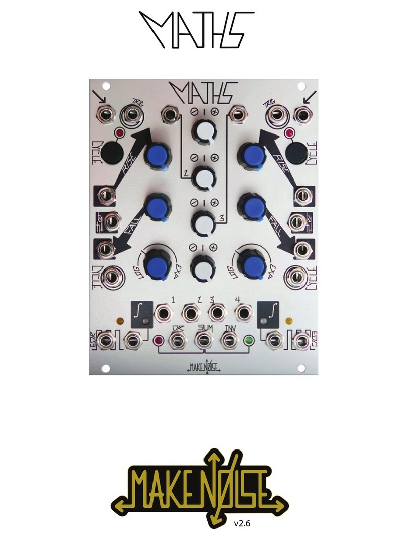
Make Noise Maths Function Module
Maths is an analog computer designed for musical purposes. Amongst other things, it can: 1. Generate a variety of linear, logarithmic, or exponential triggered
or continuous functions 2. Integrate an incoming signal 3. Amplify, attenuate and Invert an incoming signal 4. Add, subtract and OR up to 4 signals 5. Generate
analog signals from digital information (Gate/ Clock) 6. Generate digital information (Gate/ Clock) from analog signals 7. Delay digital (Gate/ Clock) information.
If the above list reads like science rather than music, here is the translation: 1. Voltage Controlled Envelope or LFO as slow as 25 minutes and as fast as 1khz
2. Apply Lag, Slew or Portamento to control voltages 3. Change the depth of modulation and modulate backwards! 4. Combine up to 4 control signals to create
more complex modulations 5. Musical Events such as Ramping up or Down in Tempo, on command 6. Initiating Musical events upon sensing motion in the
system 7. Musical note division and/ or Flam.
CHANNEL 1
IN: DC input
to circuit. Use
for lag, porta-
mento, or ASR
envelopes.
Also input to
SUM/OR bus.
Range: +/-10V.
CHANNEL 4 IN: DC input to
circuit. Use for lag, portamento,
or ASR envelopes. Also input to
SUM/OR bus. Range: +/-10V.
CHANNEL 2 IN: DC input to
attenuvertor and SUM/OR bus.
Normalized to a +10V refer-
ence for generation of voltage
offsets. Input Range: +/-10V.
CHANNEL 3 IN: DC input to
attenuvertor and SUM/OR bus.
Normalized to a +5V reference
for generation of voltage off-
sets. Input Range: +/-10V.
CYCLE BUTTON & LED: Causes the
circuit to self cycle, generating a repeating
voltage function, aka LFO. Use for LFO, clock,
or VCO. The associated LED displays red
when the cycle is enabled.
TRIG IN: Gate or pulse at input
triggers the circuit regardless of
Signal In activity. Result is a 0V -
10V function (envelope), whose
characteristics are dened by the
Rise, Fall, and Vari-Response
parameters. Use for envelope,
pulse delay, clock division, LFO
Reset (only during falling portion).
RISE ROTARY & CV IN: The rotary sets
the time it takes for the voltage function to
ramp up. CCW roation decreases rise time,
while CW rotation increases rise time. CV In
is the linear CV input for the Rise parameter.
Positive CV signals increase rise time, nega-
tive CV signals decrease rise time, with re-
spect to the Rise rotary setting. Range: +/-8V.
FALL ROTARY & CV IN: The rotary Sets
the time it takes for the voltage function to
ramp down. CCW rotation decreases fall
time, while CW rotation increases fall time.
CV In is the linear CV signal input for the Fall
parameter. Positive CV signals increase fall
time, while negative CV signals decrease fall
time, with respect to the Fall rotary setting.
Range: +/-8V.
BOTH CV IN: Bi-Polar Exponential CV
signal input for entire function. Positive CV
signals decrease total time while negative CV
signals increase total time. Range: +/-8V.
CYCLE IN: On gate high, circuit will cycle.
On gate low, the circuit will not cycle (unless
the CYCLE button is engaged). Requires
minimum +2.5V for high.
CHANNEL NOTE: Channel 1 & 4 are identical, except for EOR / EOC. So only Channel 1 (in
Green), and any differences, are explained below. Channel 4 Input is shown below, for reference.
VARI-RESPONSE ROTARY: Sets the
response curve of the voltage function.
Response is continuously variable from
Logarithmic through Linear to Exponential to
Hyper-Exponential. The tick mark shows the
Linear setting.
EOR (END OF RISE OUT) & LED: Goes
high at the end of the rise portion of the func-
tion. 0V or 10V. The associated LED indicates
the states of the EOR output. Lights when
EOR is high.
EOC (END OF CYCLE OUT) &
LED: Goes high at the end of the fall
portion of the function. 0V or 10V. The as-
sociated LED indicates the states of the
EOC output. Lights when EOC is high.
CHANNEL 1 ATTENUVERTOR
ROTARY: Provides for scaling, attenu-
ation and inversion of the signal being
processed or generated by channel 1.
Connected to Channel 1 Variable Out
and SUM/OR bus.
CHANNEL 4 ATTENUVERTOR
ROTARY: Provides for scaling, attenu-
ation and inversion of the signal being
processed or generated by channel 4.
Connected to Channel 4 Variable Out
and SUM/OR bus.
CHANNEL 2 & 3 ATTENUVER-
TOR ROTARIES: Provides for scaling,
attenuation, amplication, and inversion
of the signal patched into Channel 2 or 3.
Connected to Channel 2/3 Variable Out
and SUM/OR bus.
UNITY SIGNAL
OUT & LED:
Signal from the
Channel 1 circuit. 8V
peak to peak when
cycling. Otherwise,
the output follows
the amplitude of the
input. The associ-
ated LED indicates
activity within the
circuit. Positive volt-
ages display green,
while negative volt-
ages display red.
SUM BUS LEDS: Indicates voltage activity in the SUM bus (and therefore the INVerted SUM as well). A red
LED indicates negative voltages. A green LED indicates positive voltages.
OR BUS
OUT: Result
of the Analog
Logic OR
function with
respect to
the settings
of the At-
tenuvertor
rotaries for
channels 1,
2, 3 and 4.
Range: 0V to
10V.
SUM BUS
OUT:
Sum of the
applied volt-
ages with
respect to
the settings
of the At-
tenuvertor
rotaries for
channels
1, 2, 3 and
4. Range:
+/-10V.
INV BUS OUT: Signal from SUM Out
turned upside down. Range: +/-10V.
MATHS is laid out top to bottom, with
symmetrical features between Chan-
nel 1 and Channel 4.
The signal inputs are at the top,
followed by the panel controls and
control signal inputs at the middle.
The signal outputs are at the bottom
of the module. LEDs are placed near
the signal they are indicating.
VARIABLE OUTS: The applied signal,
as processed by channels 1, 2, 3, or 4
controls. Normalized to the SUM and
OR busses. Inserting a patch cable will
remove the signal from the SUM and OR
busses. Output range: +/-10V.
Maths Tips & Tricks
●Longer cycles are achieved with more Log. response curves. The fastest, sharpest functions are achieved with extreme Exp. response curves.
●Adjustment to the response curve will affect Rise and Fall times.
●To achieve longer or shorter Rise & Fall times than available from the Rotaries, apply a voltage offset to the CV Signal Inputs. Use Ch.2 or 3 for this.
●Use the INV SUM Out where you require reversed modulation but don’t have means for inversion at the CV destination (ex.: Mix CV In on Echophon).
●An INV signal from Maths back into the Maths at any CV input is useful for creating responses not covered by the Vari-Response rotaries alone.
●When utilizing the SUM and OR outputs, set any unused Ch. 2 or 3 Attenuvertor Rotaries to Noon, or insert a dummy patch cable into the associated
channel Input. This will avoid unwanted offsets.
●The OR output will not respond to, or generate, negative voltages.
●The EOR and EOC are useful for generating complex CV functions where Ch. 1 and Ch. 4 trigger from each other. Patch to each other’s Trigger,
Signal, and CYCLE inputs.

©2015 - Compiled by Robert Anselmi Reason101.net Visit www.makenoisemusic.com for full manual
Make Noise Passive Multiple & CV Bus Utility Modules
The Passive Multiple is a simple but important module that allows for sending a signal to multiple destinations. Within the Make Noise system the Multiple may
also be used for combining clock, gate and pulse signals together to create interesting timing sources (in other words, it acts as a Gate combiner aka logic OR
circuit). It has 9 inter-connected sockets that may be split into different group combinations depending upon how it is patched. The jacks circled in white will
make or break the interconnects between the 3 groups of three, thus allowing for three 3-way, one 5-way / one 3-way or one 7-way multiple. The Multiple is pas-
sive. The Make Noise system does not require Buffered Multiples since all critical control signals are already buffered.
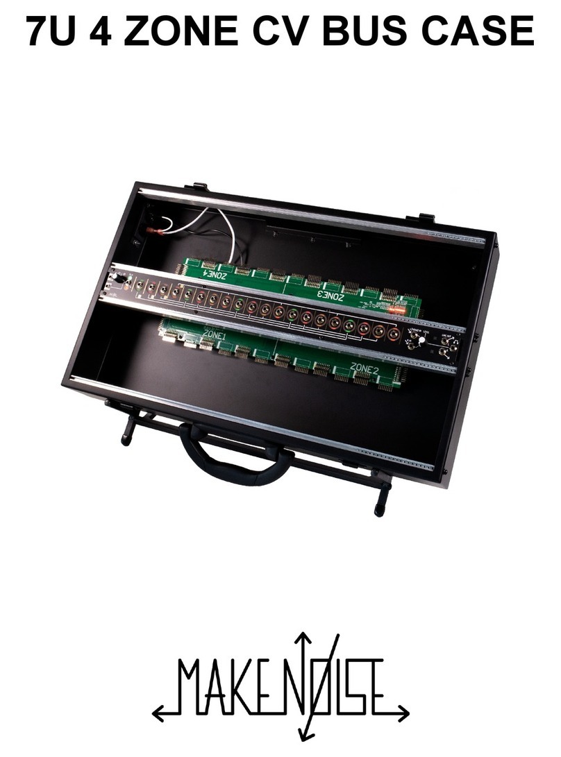
The CV Bus provides visual indication of level, rate and polarity for up to 4 color-coded control signals that will be shared throughout a patch. They are distribut-
ed across the center of the system allowing for quick, clean and intuitive patching. The visual indication makes navigating complex patches easier and intuitive.
The CV Bus also has the tools needed for integrating the Make Noise system with the outside world. A 1/4” Mono input with plenty of gain allows for bringing
external signals into the system. The optimal 10Vpp signal level is visually indicated. A high quality Stereo Line Driver converts powerful modular synthesizer
signal levels to the commonly used Line Level. There is mini-jack inputs for Left and Right, a single Master Volume control, and a TRS Stereo 1/4” output jack.
This output is capable of driving long cable out to a PA System or a set of Headphones. It has AC coupling and a built-in limiting circuit (with visual indication).
INPUTS & OUTPUTS: Each jack can operate as an input or an output, except the white-circled jacks, which are “input only.”
Patching into one input creates a split of that input into all other jacks, which can then operate as outputs, where the input signal can
be tapped. A few other notes:
●You can input a signal into any one of the 9 jacks. The output is tapped from any of the other jacks.
●You can split any kind of signal: audio, CV, or gates.
●You can also mix (combine) clock, gate and pulse signals (OR logic). You cannot mix audio or other CV signals. Combination
of Audio / other CV signals is not supported, but will not damage anything.
●The only time a buffered multiple is needed is when control voltage is sent from an unbuffered output to multiple destinations
that require unity at the input; typically, 1v/oct inputs. Because all critical CV outputs in the Make Noise System are buffered, a
passive multiple is all that is needed.
●White-circled jacks make or break connections within the Multiple. While all other jacks are normalled, meaning, they split the
signal to all other outputs, the white-circled jacks are “input only,” and are not used as outputs. In this way, you can create
various multiple combinations: three 3-way, one 5-way & one 3-way, or one 7-way multiple. From a practical standpoint, here’s
what that means:
■3x (1 input / 2 outputs)
■1x (1 input / 4 outputs) and 1x (1 input / 2 outputs)
■1x (1 input / 6 outputs)
INPUTS & OUTPUTS: As with the standard Multiple, each jack can operate as an input or an output. However, there are no “input only” jacks, and jacks are
not “normalled” along the entiere bus. Instead, there are four distinct busses. This means that you can patch an input anywhere on the system to produce four
corresponding output splits. The lines on the faceplate denote the four busses.
●You can input a signal into any one of the 20 jacks. The outputs are then tapped from the four jacks associated to the input (noted by the lines on the
faceplate). In order to create additional splits of a single input, patch from one of the split outputs into a second bus line. For example, if you input a signal
on the rst jack (at the left), Bus 1 outputs 4 signals via the Bus one output jacks. Take on of those outputs and patch into the second jack (from the left) to
create an additional set of 4 output splits. Bus 1 now has 3 outputs (the fourth being sent into Bust 2 input), and Bus 2 has 4 outputs (for a total of 7 splits
of the one input signal). The CV Bus is a 4 input / 16 output multiple.
●You can split any kind of signal: audio, CV, or gates.
●You can also mix (combine) clock, gate and pulse signals (OR logic). You cannot mix audio or other CV signals. Combination of Audio / other CV signals
is not supported, but will not damage anything.
●The only time a buffered multiple is needed is when control voltage is sent from an unbuffered output to multiple destinations that require unity at the input;
typically, 1v/oct inputs. Because all critical CV outputs in the Make Noise System are buffered, a passive multiple is all that is needed.
●Here are some of the combinations that can be created with the CV Bus:
■4x (1 input / 4 outputs)
■2x (1 input / 7 outputs) -- note: 1 split output is sent into a second bus input.
■1x (1 input / 10 outputs) -- note: 2 split outputs are sent into second and third bus inputs. and 1x (1 input / 4 outputs)
■1x (1 input / 13 outputs) -- note: 3 split outputs are sent into second, third, and fourth bus inputs.
For an informative video about the CV Bus, see here: Make Noise System Tutorial 3: Control Voltage (CV) and Polarity.
INPUT
& GAIN
ROTARY:
1/4 inch audio
input jack
for outside
sources to be brought into the
modular system. Since line levels
are lower than modular levels,
there is a unipolar Gain Rotary to
increase the amplitude of the audio
input signal.
OUTPUT & LED CLIP
INDICATOR: After the
audio signal / gain path, you
can use this 1/8 inch jack
to output the audio to any
destination in your modular
system. The LED Clip
Indicator will show as a red
exclammation mark if the
level is too hot / volume too
high. If this happens, ease
back on the Gain Rotary.
IN/OUT LEVEL, RATE, POLARITY & COL-
OR CODING: Surrounding each Input & output
jack is an LED. This indicates the following: Level
is indicated by the brightness of the LED. Brighter =
higher level, duller = lower level. Rate is indicated
by the pulse of the LED. Polarity is indicated by
position of the LED. Positive = upper circle half lit,
negative = lower circle half lit. Color indicates the
different busses on the system. Green is bus 1, red
is bus 2, yellow is bus 3, and orange is bus 4. The
colors are a great visual indicator, so that you can
see which signals are being output on each bus.
L (MONO) & R
INPUT & LEV-
EL ROTARY:
This is the mono
/ stereo audio
output from the
modular system.
The associated
unipolar Level
Rotary allows
you to adjust the
output volume.
LINE OUT
(TRS): 1/4
inch Stereo
TRS audio
jack that can
be used to
send the nal
modular output
to headphones,
PA system,
or DAW for
recording.
PASSIVE MULTIPLE
CV BUS (available as part of the Shared System with CV Bus and Black & Gold Shared System)

©2015 - Compiled by Robert Anselmi Reason101.net Visit www.makenoisemusic.com for full manual
Make Noise Mysteron Digital Waveguide Module
The Mysteron is a voltage controlled dual digital waveguide algorithm that is a bit of a mystery even to those of us involved in its design. Despite being
completely digital, it is highly organic, displaying variation in outcome often seen only in nature. It is a formless blob of DSP that you grow, modulate and patch
program into new sounds, some vaguely recognizable and others completely otherworldly. The range of sounds possible is quite large. From pianissimo to
fortissimo, short percussive bursts to bowed, sustaining pitches. The two waveguides can be pitched together or independently, mutated with harmonic or inhar-
monic waveforms and fed back into themselves or each other.
COARSE PITCH ROTARY & LED: Sets length of waveguide or
perceived pitch of sound, roughly 5 octaves. Quantized mode when set
fully CCW. The “Mystery” LED indicates mutations. It ashes slowly on
bowed/cross-feedback modes, and ashes quickly in quantized mode.
OUTPUT: AC coupled audio
output. Range: ~10Vpp (de-
pending on settings; especially
Impulse).
DEPTH CV INPUT & ATTENUATOR:
The Depth CV Input is unipolar. Range: 0V to
+5V. The associated Depth Attenuator sets
how much the waveguides are mutated. It is a
unipolar combo control. With nothing patched
to Depth CV In, it works as a standard panel
control. With a signal patched, it works as a
level control for that signal.
GENERATION ROTARY, ATTENUVER-
TOR & CV INPUT: The Generation Rotary
sets feedback of the output of the waveguides
back to their inputs. At 12 noon there is no
feedback. Degenerative feedback is CCW
from NOON, and Regenerative feedback is
CW from NOON. The Generation CV Attenu-
vertor is a bipolar attenuator for Generation
CV In. The Generation CV Input is a bipolar
signal input. Range: +/-4V.
FINE PITCH ROTARY: Adjust per-
ceived pitch by +/- 12%.
IMPULSE CV INPUT & ATTENUATOR:
The Impulse CV Input is unipolar. Range: 0V
to +5V. The associated Impulse Attenuator
sets the strength of excitation, allowing for
control over amplitude and harmonics. It is a
unipolar combo control. With nothing patched
to Impulse CV In, it works as a standard
panel control. With a signal patched, it works
as a level control for that signal. Must be set
greater than 0% to achieve an audible sound.
EXCITE INPUTS & LEDS: Gate
inputs for excitation. Mysteron will create
no sound unless you patch something
to at least one of these inputs. Requires
a clock/gate signal amplitude of at least
1.5V and width of at least 6ms. The
associated Excite LEDs provide visual
indication of the Mysteron’s excitation.
PITCH 2 CV INPUT: The exponential
pitch control input. Range: 0V to +5V.
Quantized mode range: 0V to +3V. Re-
sponse is 1V/Oct. Engage quantize mode
for superior tracking.
!! IN (GATE): This is the gate input for deter-
mining the algorithm behavior. With Mutation
Depth fully CCW, this changes the response of
the Excite parameter for bowed attack. When
not fully CCW, cross couples feedback paths
of waveguides into each other (the “Mystery”
LED Flashes to indicate the status). Requires
a clock/gate signal amplitude of at least 1.5V
and width of at least 6ms to operate.
TYPE ROTARY, ATTENUATOR &
CV INPUT: The Type Rotary sets the
Type of Mutation. The Type CV Attenu-
ator is a unipolar level control for the
Type CV Input. The Type CV Input is a
unipolar CV input for the Type parameter.
Range: 0V to +5V.
PITCH 1 CV INPUT & ATTENU-
VERTOR: The Pitch 1 CV Input is the
exponential pitch control input. It is not
applicable in quantized mode. Range: +/-
5V. The associated Pitch 1 Attenuvertor
is a bipolar control which adjusts the level
of the signal coming into the Pitch 1 CV
Input.
Mysteron 101
Making Sound: When the Mysteron is Excited (via the Excite Inputs), a burst of energy (in the form of noise and other waveforms) is injected into the wave-
guide. The Impulse parameter sets the strength of this excitation, thus allowing for control over both amplitude and harmonics. Impulse must be set greater
then 0% to achieve audible sound. At lower settings, the sound will have fewer harmonics and less impact. This parameter could also be used as a digital
VCA while the Mysteron is self-oscillating.The Excite inputs are wired in a normalization scheme, so that with either one patched, the other is triggered as
well. Using both Excite inputs results in the two waveguides having different lengths, with the possibility of creating two independent pitches and timbres.
Controlling Pitch: The Pitch control sets the length of both waveguides. The length of the waveguide determines perceived pitch of the resulting sound. It
will also alter the timbre of the sound. The Pitch Rotary, Pitch 1 and Pitch 2 all have an exponential response with a range of roughly 5 octaves. At the lowest
end, the sounds are lower pitched and take longer to decay. Therefore, it is harder to discern the pitch, as there are greater harmonics. At the middle, the
sounds are shorter and have fewer harmonics, making it easier to discern their pitch. At the highest end, the sounds have the potential to become so short
it is hard to determine the pitch. Changes to the Pitch controls are applied to the most recently excited waveguide. If both waveguides are excited together,
then both are the same length. The Excite inputs are normalled so patching into just one excites both together. Using both Excite Inputs independently, it
is possible to have the two waveguides at different lengths, thus making two differently-pitched sounds. Removing all modulation from the Pitch 1 CV In,
and setting the Pitch Rotary fully CCW engages quantize mode. The Mysteron remains in quantize mode as long as the Pitch Rotary remains at 0% with
nothing patched into Pitch 1 CV In. Quantize mode is indicated by the double ashing of the “Mystery” LED. This forces the Mysteron to adhere to a 12-tone
chromatic scale, with the pitch determined by Pitch 2 CV In. This is excellent for using the Mysteron in a melodic way alongside other sound sources such as
an STO or DPO VCO.
Sound Sculpting: Once the Mysteron is excited, the Generation Rotary sets the feedback of the output of the waveguide back to the input. Degenerative
feedback saps energy from the algorithm, making the sounds shorter and more percussive. Regenerative Feedback grows energy in the algorithm, making
the sounds longer and less percussive. At 100% feedback, the sound is almost a bowed type dynamic. With Depth fully CCW (no Mutation), the “!!” Gate
Input engages an alternate response to the Excite inputs for a bowing effect. With Depth greater than 0%, the “!!” Gate Input cross couples the output of
each waveguide into the input of the other waveguide. This is inuenced by the analog acoustic modeling synthesis of Ron Berry. With Mutations occurring,
the results are more complex and depend upon the Type and Depth settings. The Mystery LED ashes to indicate these behaviors. The Mutation section
features contains the Depth and Type controls. With Depth set fully CCW, Type will do nothing. To hear the effects of Type, Depth must be turned to at least
10%. Depth sets the amount of mutated energy injected into the waveguide and Type selects the form of mutation. What is actually happening is that the
waveguide is being excited more than just noise. The Type control is scanning through other waveforms to be used to excite the waveguide. Depth blends
these other waveforms with the noise (from 0% WT/100% Noise to 100% WT/0% Noise). This dramatically changes the timbre and pitch of the sound. The
“Mystery” LED lights to indicate Mutation. All other controls (Pitch, Impulse, Generation, !!) are still effective during Mutation.
Tips & Tricks: 1) The Impulse parameter could be used as digital VCA. 2) For melodic tracking, set the Pitch Rotary fully CCW (quantize mode), and use
only Pitch 2. Fine Tune will help to match the Mysteron to a VCO tuning. 3) For simplest usage, patch a gate or clock to only one Excite input.

©2015 - Compiled by Robert Anselmi Reason101.net Visit www.makenoisemusic.com for full manual
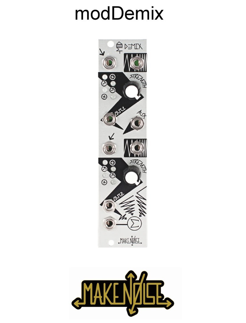
Make Noise Optomix & modDemix Low Pass Gate & VCA Mixer Modules
The Optomix is a two channel Low Pass Gate, providing simultaneous voltage control over amplitude and frequency content of a signal. It is in essence, a
Voltage Controlled Filter Amplier (VCFA) that has an extremely organic response to control signals. Additionally, the Optomix offers a summing stage complete
with an auxiliary input, allowing for the chaining of multiple units to create larger mixes (this also works well in combination with the modDemix. The modDemix
features 2 identical direct-coupled balanced modulator circuits that may be used together or independently for Ring Modulation, VCA, Mixer, Signal Multiplica-
tion, Voltage Controlled Polarization, Attenuation and more.
CHANNEL 1 SIGNAL IN:
DC signal input, capable of ac-
cepting audio or CV. Range: Up
to 18Vpp.
CHANNEL 1 SIGNAL IN: DC signal input, capable of accepting audio or CV.
CARRIER CV IN: Deter-
mines amplitude & phase of
Channel 1 Signal In.
STRENGTH ATTENUA-
TOR: Unipolar attenuator
for Carrier CV In: Normalized
to +5V so that with nothing
patched to the Carrier CV
In, the attenuator acts as a
manual Carrier attenuator.
Range: 0V-5V.
DAMP CV IN: DC CV input for the cor-
responding channel’s damping param-
eter. Normalized to +8V. Range: 0V-8V.
CONTROL CV IN: DC, highly sensitive CV
input for the corresponding channel’s vactrol
gate. Normalized to +8V. Range: 0V-8V.
DAMP ATTENUATOR: Uni-
polar attenuator for the Damp
CV Input. With nothing patched
to the Damp CV In, the attenu-
ator acts as a manual damping
attenuator.
CONTROL ATTENUATOR: Unipolar
attenuator for the Control Input. With nothing
patched to the Control CV In, the attenuator
acts as a manual control attenuator.
CHANNEL 1 SIGNAL OUT: DC output of the signal applied to the input,
as pro-cessed by the LPG. Range: 10Vpp (depending on settings and source
material).
Channel 1 vs Chan-
nel 2: both channels are
identical, except as noted
here. If you don’t see a
description of the Chan-
nel 2 parameter, refer to
the Channel 1 descrip-
tions for information.
Channel 1 vs Channel 2:
Similar to the Optomix, both
modDemix channels are identical,
except as noted here. If you don’t
see a description of the Channel 2
parameter, refer to the Channel 1
descriptions for information.
STRIKE INPUT: Gate input for striking or plucking the vactrol. Expects 8V
Gate. It acts as a fast attack envelope with slow amplitude response affecting
the LPG. Combined with the Damp parameter, Strike allows for the program-
ming of percussive sounds (sharp Attack w/ CV Decay), without the need for a
separate envelope generator.
Further Information
Optomix: As a VCA, Optomix has a moderate attack response and slow decay response, meaning that it turns on quickly, but takes a while to shut off,
yielding a smooth natural sounding decay to almost any sound processed dynamically. The sound is often described as “ringing,” and while the circuit is
not technically ringing, that does describe many of the sounds possible when using the Optomix to process complex signals generated through FM or Ring
Modulation. As a VCF it is a mild, nonresonant Low Pass circuit acting to gently reveal (or hide) the sharper edges of a sound. This characteristic also adds
to the “ringing” effect. As the amplitude of the sound decays, there is a simultaneous loss in high frequency content that is similar to the natural loss of en-
ergy in idio and membranophonic instruments. The Optomix, being a vactrol-based circuit, will never have the speed or tight tolerances found in many other
VCA and VCF circuits. If you seek to program extremely short sounds, clicks, pops and ticks, then the Optomix is not the best choice. What the Optomix
does offer is extremely low noise and low distortion and a smooth, natural sounding circuit.
modDemix: The modDemix consist of 2 identical direct coupled circuits that may be used together or independently to process audio or control signals
by means of amplitude modulation and the many derivatives of AM such as double/ single-sideband, voltage controlled amplication/ attenuation, voltage
controlled polarization or multiplication and of course, ring modulation. The modDemix is a specialized amplitude modulation circuit that could be thought of
as a “Thru-Zero VCA,” meaning that in addition to the AM, when the Carrier signal (called Carrier CV) changes phase, the resulting signal’s phase will ip as
well. What makes the modDemix unique when compared to other balanced modulators, is that because it is Direct Coupled, it will perform wonderfully both
as anaudio rate modulator to implement Ring-Modulation, and as a control rate modulator to implement multiplication of CV. Also, the circuit used will, with
ease, turn off around 0V at the Carrier CV In; a characteristic that makes the circuit behave very well as a VCA. Both circuits feed a “Sum” stage, allowing
the module to be used as a voltage controlled mixer. The Strength attenuators are “combo knobs,” acting as unipolar panel controls. In practice, this means
the summing stage can also be a mixer with amplitudes set by the 2 Strength controls. An Aux In allows for chaining multiple modDemix (or Optomix) units
to create larger mixes. The attenuator allows for setting the Strength or Level of the incoming signal. When performing ring modulation, adjusting Strength
will alter the integrity of the resulting modulated and/or demodulated signal, thus affecting the timbre as well as the amplitude. In most other uses, Strength is
directly related to the amplitude of the resultant signal.
AUXILIARY IN: DC signal
input to the Sum circuit, to al-
low for the chaining of multiple
Optomix and modDemix units to
create larger mixes. Capable of
accepting audio or CV signals.
Range: up to 10Vpp (depending
on settings and source material).
AUXILIARY IN: DC signal
input to the Sum circuit, to al-
low for the chaining of multiple
modDemix and Optomix
units to create larger mixes.
Capable of accepting audio
or CV signals. Range: up to
10Vpp (depending on settings
and source material).
CHANNEL 2 SIGNAL IN:
DC signal input, capable of ac-
cepting audio or CV. Normalized
to Channel 1 Signal Out, for
series processing. Range: up to
10Vpp (depending on settings
and source material).
CHANNEL 2 SIGNAL IN: DC signal input, capable of accepting audio or CV.
Normalized to Channel 1 Signal Out, for series processing.
CHANNEL 1 LEDs: LED indication of signal activity in four quadrants. Verti-
cal position represents amplitude and phase of input signal; horizontal position
represents amplitude and phase of Carrier CV In signal.
CHANNEL 1 SIGNAL OUT: Output of the processed signal from Channel 1.
SUM OUT: The sum or mix
of all signals processed by the
Optomix (Channel 1 & 2 In, and
Aux In) is sent out here. Range:
10Vpp (depending on settings
and source material).
SUM OUT: The sum or mix of all signals processed by the modDemix (Channel
1 & 2 In, and Aux In) is sent out here.

©2015 - Compiled by Robert Anselmi Reason101.net Visit www.makenoisemusic.com for full manual
Make Noise Phonogene Sampler / Looper Module
The Phonogene is a digital re-visioning and elaboration of the tape recorder as musical instrument. It takes its name from a little known, one of a kind instru-
ment, used by composer Pierre Schaeffer. While not an emulation, it expands upon the original concepts. It is informed by the worlds of Musique Concrète
(where speed and direction variation were combined with creative tape splicing to pioneer new sounds) and Microsound (where computers allow for sound to
be divided into pieces smaller then 1/10 of a second, and manipulated like sub-atomic particles). Having CV control over every parameter, it is most dynamic
as a digital audio buffer for the modular synthesist. The Phonogene is comprised of a pair of tool-sets: Tape Music tools allow for sounds to be recorded on the
y, layered, manually cut into pieces, re-organized, and played backward or forward at differing speeds. The Microsound Tools allow for you to divide the audio
buffer into progressively smaller pieces called Genes (aka particles, grains, granules). You can then step through those pieces in chronological order, and/or in
nonlinear fashion (providing random access of the audio buffer). Both sets of tools complement each other, which is why they were grouped into one module.
SIGNAL IN & ATTENUATOR: Audio
input. Line level or modular synth levels
are acceptable. AC Coupled. The associ-
ated Signal In Attenuator sets the input
level. For line level, set at 70% CW (2Vpp),
and for mod synth levels, set at 30% CW
(10Vpp); noted on the faceplate.
SOUND ON SOUND CV IN: Sets the mix of previ-
ously recorded loop with live Signal input when recording,
to allow for SOS-type “overdubs.” Also allows for setting
monitoring level of live input signals with previously
recorded loop. Can also be used as a CV cross-fader
(between live & loop) or VCA for loop (no live signal).
Range: 0V to 10V, linear response. Normalized to +10V.
SOUND ON SOUND AT-
TENUATOR: With nothing
patched to SOS CV In, this
works as a standard panel
control. With signal patched
to SOS CV In, this works as
an attenuator for that signal.
SIGNAL OUT:
Audio signal output.
10Vpp, depending on
Signal In Attenuator
setting and the source
material. AC coupled.
SLIDE ROTARY: Manual bipolar rotary
for scanning the pieces of sound that result
from setting Gene-Size to greater than
10%. Moves/slides through the Genes (aka
grains). Allows for scrubbing of the recorded
material, and is always dependent upon the
Gene-size setting.
SLIDE CV IN & ATTENUVERTOR:
Bipolar CV input for Slide. Range +/-4V.
The associated Slide Attenuvertor sets the
bipolar level for the incoming CV.
GENE-SIZE CV IN & ATTENUATOR:
Unipolar CV input setting size divisor of
audio buffer, dividing with respect to the
buffer size as set by Record or Splice length.
This parameter “auto-splices” the recorded
material like a machine. Operates with great
precision and can cut pieces to a granular
level. Nondestructive. At 0V there is no
effect. Range 0V to +8V. The associated
Gene-size Attenuator sets the level for the
incoming CV. It is unipolar.
GENE SHIFT CV IN: A clock signal at
this input advances Phonogene to the next
Gene, in chronological order. Always depen-
dent upon the Gene-size setting. Needs at
least 1.5V trigger signal to operate.
SPLICE CV IN: Input for using external
signal to splice the loop. Sees only rising
edge of the signal. Needs at least 1.5V trig-
ger signal to operate.
EOS CV OUT & LED: Outputs a short 4
ms pulse at the end of each Splice. With no
Splices, EOS outputs a pulse at the end of
each loop. The associated EOS LED ashes
at each pulse output.
GENE-SIZE ROTARY: Manual unipolar
control which sets Gene-Size divisor.
Recording Time and Quality: The Phonogene audio buffer is 2MB, nonvolatile, high number of fast read and write cycles. Nonvolatile means the
Phonogene remembers both samples and splices on power down. The high number of read and write cycles is key to longevity of the module. High speed
read and write cycles allow for short sample times, making microsound possible. Because the record and playback frequency is continuously variable from
88.2khz to 5.5khz by the Varispeed controls, the longest possible recording or loop length is determined by the speed of the playback/recording. Therefore,
long recordings may be achieved, but at the cost of a lower sample rate, meaning the resulting recordings will be of lower sound quality. A “Mid-Fi” setting
may be achieved by setting the Varispeed rotary at around 50%, so that both Varispeed LEDs are off. This records a good quality, 2-second sample length,
and allows for a good range of speed variation. Playback is stopped while you record. To record shorter samples at higher quality, set the Varispeed rotary
CCW. To record longer samples at lower quality, set the Varispeed rotary CW. Sample length can range from approximately >0 to 30 seconds.
Erase Routine: Hold the Splice button for 3 seconds to erase all splices at once. The Rec LED ashes to indicate splices have been erased. If you then
press the REC button while still holding the Splice button down, the Recording is also erased. Note: Erasing splices is non-destructive to your audio.
Broken Echo Mode: This hidden function allows for realtime processing of audio signals. To enter Broken Echo mode, create a sample/loop/Splice (just
press the Rec button and record enitre memory bland, for example). Then press and hold the Rec button until you pass through the EOS (EOS ashes)
and Rec will be stuck On. To exit Broken Echo mode, press the Rec button again (do not Hold it though, or you will go back into Broken Echo mode). In this
mode the Phonogene is similar to the Echoplex, with the SOS switch activated. This is similar to covering the Erase head of a tape recorder, allowing a spool
of tape to be recorded over and over and over again, without erasing the previous recordings. This is a great mode for building walls of sound, drones, or
making crude echo FX. Phonogene still minds Splices, Varispeed, Gene-size, Gene Shift, and Slide. Any modulation of these parameters are recorded. Be
sure to set the SOS Attenuator control according to your desired results. For example, live input processing requires the attenuator to be set at around 50%,
while massaging captured content requires a setting of 100% Wet. Adding or removing splices during Broken Echo Mode is not supported.
VARISPEED ROTARY & LEDS: Manual
bipolar speed and direction control. When
set to 50% playback is stopped, turning CCW
from 50% decreases playback speed in
backward direction, turning CW from 50% in-
creases playback speed in forward direction.
Two LEDs are associated with this rotary. The
2 associated LEDs show in which direction
the Phonogene is playing. The left (blue)
LED indicates reverse playback. The right
(orange) LED indicates forward playback.
When no LEDs are lit, playback is stopped.
LEDs also ash when a new splice is found
(see the Organize controls).
VARISPEED CV IN & ATTENUVER-
TOR: Bipolar speed and direction control
where 0V stops playback, positive control
signal increases playback speed in forward
direction, negative control signal increases
playback speed in reverse direction. Range
+/-4V. The associated Varispeed Attenuver-
tor sets the bipolar level for the incoming CV.
ORGANIZE CV IN & ATTENUATOR:
Unipolar CV input which selects the next
Splice to be played. The currently selected
Splice will play to the end before the next
Splice is selected. The Varispeed LEDs ash
whenever this control nds a new Splice.
Range: 0V to +5V. The associated Organize
Attenuator sets the level for the incoming
CV. It is unipolar.
RECORD BUTTON & LED: Manual, momen-
tary button to toggle record on/ off. The Record
LED indicates when recording is taking place.
When not lit, recording is not taking place.
SPLICE BUTTON: Pressing drops splice marker
on a loop. When loop is Organized, the splices (re-
sulting audio segments) are re-arranged according
to the Organize CV. Phonogene plays whichever
splice is selected by Organize parameter.
ORGANIZE Rotary: Manual Unipolar
control which selects the next Splice to be
played. The Varispeed LEDs will ash when-
ever this control nds a new Splice.
PLAY & RECORD CV INS: Play CV In: At each rising edge signal applied to Play CV In, playback
is triggered. At the end of loop or splice, Phonogene looks at the incoming CV, and if high, it plays again.
If low, it does not play. This Input is normalized high. With nothing patched, play is continuous. Needs at
least 1.5V trigger signal to operate. Record CV In: Toggles Record on/off. When recording from a cleared
buffer, the rst record cycle sets the record length, so be sure to perform the Erase Routine to achieve a
new recording. Sees only rising edge of signal. Needs at least 1.5V trigger signal to operate.

©2015 - Compiled by Robert Anselmi Reason101.net Visit www.makenoisemusic.com for full manual
Make Noise Pressure Points & Brains Expander Control Module
Pressure Points is a controller in which 1 of 4 sets of 3 tuned voltages are selected by touching the corresponding printed copper wire at the bottom of the in-
strument. Touching Pressure Points, you become part of the circuit, generating a gate signal (Gate Out), a control signal proportional to the amount of pressure
applied (Press Out) and activating the corresponding Stage. The Tuned Voltages for the activated Stage appear at their respective X, Y and Z Outs. In this way,
Pressure Points is like an analog sequencer that is played by hand.
2 pots allow the circuit to be adjusted for desired playing response. Up to 4 of these modules may be chained together to create controllers of varying size and
complexity. The Gate and Press Outs are normalized to their respective Combined bus which is output at the last Gate or Press Out in the chain. In addition,
stages can also be selected via clock inputs with the separately purchased expander module, Brains.
PRESSURE OUTS: Unipolar CV Outputs 1, 2, 3, and 4. Sends out a CV
signal based on the pressure applied to the corresponding touch plate. Pres-
sure Outputs are displayed using yellow output arrows on Pressure Points.
GATE OUTS: Gate Outputs 1, 2, 3, and 4. Sends out a high gate signal when
the corresponding touch plate is pressed, and stays high until a new touch plate
is pressed (a new “stage” is enabled). Gate Outputs are displayed using white
output arrows on Pressure Points. Only one is referenced here (Gate Out 4).
TUNED VOLTAGE ROTARIES: The
top row is Tuned Voltage row X, the middle
row is Y, and the bottom row is Z. X range:
0V to 8V. Y & Z range: 0V to 5.5V.
TUNED VOLTAGE OUTS: Each row of
Tuned Voltages has a corresponding CV
Output that that can be sent to other CV
inputs in your system. When a “stage” is
enabled with Pressure Points by pressing a
touch plate, the corresponding vertical col-
umn of Tuned Voltages are simultaneously
sent out to all 3 CV Outputs.
TOUCH SENSITIVITY POTENTIOM-
ETER: Set the Touch Sensitivity Adjustment
Potentiometer further CCW when you want
coarser Touch Plate response (less sensitive
to the touch). Set it CW when you want ner
Touch Plate response (more sensitive to the
touch).
TOUCH PLATES: Touch Plates 1, 2, 3,
& 4. Pressure Points requires the develop-
ment of a technique, and clean, bare
hands. Touching the upper-most portion of
the touchplate with as little of your nger as
needed to activate the circuit, will generate
simultaneous Pressure and Gate signals,
which are sent to the Outs at the top of the
associated vertical column. Also, the three
Tuned Voltages X, Y, & Z (as set by the col-
umn’s Tuned Voltage rotaries), found in the
middle of the module, are sent out to their
corresponding Outs on the module’s left
side. Each time a Touch Plate is pressed,
5 signals are simultaneously sent out to
control other parameters in your system:
Pressure, Gate, and 3 Tuned Voltages.
Laying more of your nger down on the
touchplate, and pressing harder, will gener-
ate a pressure control voltage proportional
to amount esh mashed into the copper of
the touchplate. Pressing harder, more of
your esh comes into contact with a sensi-
tive point in the circuit.
DIGITAL TRIMMER: If you cannot
obtain the desired response, you might
need to adjust the internal Digit Trimmer
to compensate for size & moisture of your
ngers, as well as playing technique and
style of system setup (vertical, horizontal,
angled). This requires a trimmer tool or
jeweler’s screwdriver, and access to the
module from the right side, where the Dig-
it Trimmer is located on the circuit board.
Always turn the power for Pressure Points
off while adjusting the trimmer. Default
setting is 40% CW. CCW = less sensitiv-
ity. CW = more sensitivity. You will need
to experiment with settings to achieve the
desired playing response.
Pressure Points Tips & Tricks
●The top row of Tuned Voltages range 0 to
+8V, and may be used to generate gate
signals, where full CCW is Gate Off and
full CW is Gate On.
●Process the Pressure CV Signal with a
slew limiter and attenuator on Channels
1 or 4 of Maths to achieve larger than life
modulations.
●Achieve a “Latched,” “Toggled,” or “Switch-
ing” CV signal, use two stages of Pressure
Points, where one has a tuned voltage set
to 0V (toggled Off), and the other has a
Tuned Voltage set to the desired On state
(+8V, or full CW, for example). Touch one
stage to turn On, and the other to turn Off.
●Use for preset storage, where you have 4
presets of 3 variables in a patch; variables
being set by Tuned Voltages X, Y & Z.
Additional variation is preset by apply-
ing the independent Press and/ or Gate
signals from each stage to different patch
points. If the Gate is not needed to initiate
an event, apply it to a patch point via an
Attenuator, and use it as a touch-controlled
momentary modulation.
●All Tuned Voltage and Press CV Outs will
drive a passive 4-way mult with no loading.
●All Gate Outs may be stacked to one Gate
In for Gate mixing.
ACTIVE STAGE LEDS: Lights yellow
to indicate which stage (1, 2, 3, or 4) is
currently active.
CLOCK IN: Selects next stage or number to be counted on rising edge of clock,
gate, pulse or trigger, of at least 1V. Patch here to sequence.
RESET IN: Jumps to last touched stage on rising edge of clock, gate, pulse or trig-
ger, of at least 1V. Use this input to control when the sequence is reset to the start
or beginning of the sequence.
RUN IN: Gate or logic high (of at least 1V) will tell Brains to count, and thus run
gate. Gate or logic low (below 1V) will stop Brains. Use this input to control when
the sequence is turned on or turned off.
DIRECTION IN: Gate or logic high (of at least 1V) tells Brains to count forward.
Gate or logic low (below 1V) tells Brains to count backward. Use this input to control
the forward / backward movement of the sequence.
TOUCH-GATE OUT: Generates gate high, 10V, when any Touch Plate on a con-
nected Pressure Points is touched.
TOUCH-CLOCK IN: Secondary clock activated when Pressure Points is touched.
This input serves a dual purpose. Used without a Master Clock applied to the Clock
In, events initiated by touching Pressure Points will be quantized to the timing signal
applied to the Touch-Clock In. When used along with the Clock In, a secondary
sequence will be initiated whenever Pressure Points is touched, where the length
and timing is determined by the relationship of the Touch-Clock to the Master Clock.
Also, patching a dummy cable into this input breaks the connection between the
Pressure Points Touch Plates and the sequence (stage) selection. In other words,
the Pressure Output from the Touch Plates are independant of the stage sequence,
and thus, independant of the Gate Output and Tuned Voltage Outputs.
Brains is a clocked sequential binary event machine, intended to be connected to tactile controllers such
as the Pressure Points. as an expansion module. Once connected, Pressure Points provides data input
to Brains in the form of touch-selectable Reset stage and Hold stage. Pressure Points also provides the
tuned voltages and pulses per stage. Brains, when connected to either 1 or 2 Pres-
sure Points, will drive the stage selection in a sequential fashion, at a rate deter-
mined by the incoming clock at Clock In, thus forming a 4-Step or 8-Step, 3-channel
analog sequencer. Binary control over Direction of the stage selection, Run/Stop
and Reset are provided.

©2015 - Compiled by Robert Anselmi Reason101.net Visit www.makenoisemusic.com for full manual
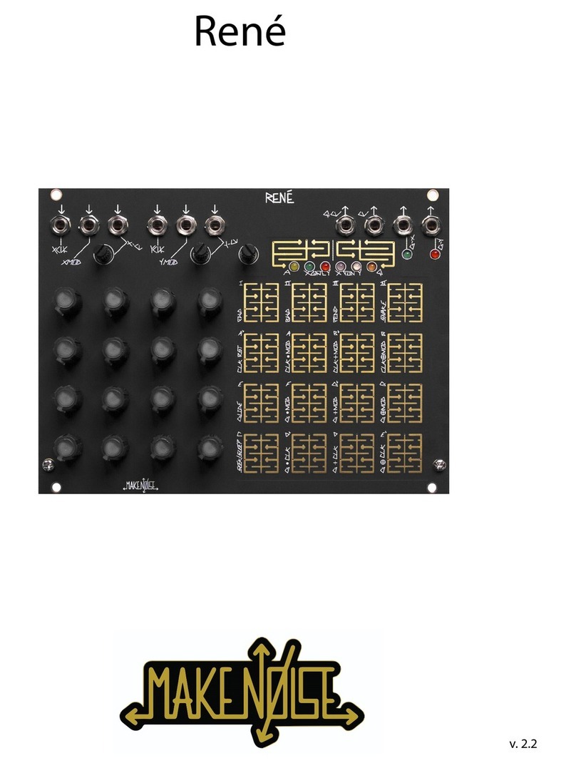
Make Noise Rene Sequencer Module
René is deep, but all you really need to know: Patch one clock to XCLK, and a second clock to YCLK, adjust clock rates and/ or divisors, tune voltages per loca-
tion (the knobs) as desired. Adjusting those two clocks relative to each other will create seemingly innite variations on the theme that is your sequence.
René is the world’s rst and only Cartesian sequencer for music synthesizers. It uses Descarte’s cartesian coordinate system to unlock the analog step se-
quencer from the shackles of linearity. Like the classic analog sequencers, there are only 16 steps, each having an associated knob with which the note for that
step is tuned. However, using René, the patterns are not limited to 16 steps in length because the path taken through those steps is, for all practical purposes,
innite. In fact, René does not “step” at all, but rather it maps coordinates to locations in a grid. As a result, it is possible to move in ways that you would never
imagine. The 16 steps on René are called “locations,” and rather than one clock input, there are two; the X axis, and the Y axis.
X-CLOCK IN: Clock/
Gate signal (of width
>.5ms and amp >2.5V)
input drives the X-
axis counter. If using
Maths to clock, then
set Vari-Response to
Linear. When René
counts Snake style,
X-CLK steps linearly
through a stored set of
coordinates; it drives
the sequence.
QCV OUT: The
quantized CV of
the currently ac-
tive location. QCV
may also yield a
stored quantized
CV (if selected on
Q Page), in which
case the corre-
sponding location
potentiometer is
no longer “live.”
Range: 4 octaves.
CV OUT:
The un-quan-
tized CV of
the currently
active loca-
tion. At the
CV Out, the
location po-
tentiometers
are always
“live.” Range:
0 to 4.5V.
GATE X & Y OUTS: These
outs reect the X- & Y-Gate
Page programming. When
René hits a location, and it is
on (lit) on the X- and/or Y-Gate
PGM Page, the out(s) go high
for a duration determined by
the X-CLK width and any PGM
logic operations for that axis
clock or gate. When counting
Snake style, the Gate Out is
always a skinny pulse (2ms).
Range: 0V (off) or +8V (on).
TOUCH PLATE SENSITIVITY CON-
TROL: To decrease sensitivity, turn
CCW. To increase sensitivity, turn CW.
CV PROGRAMMING GRID: Pots
used for programming (PGM). LED lights
indicate currently active location(s).
X IN CV ATTENUATOR: Attenuates
the incoming X-CV input signal.
Y IN-
PUTS:
Identical
to the X-
inputs, but
applied
to the
Y-Axis.
See the
X- inputs
for an
explana-
tion.
X-CV IN: CV at this input
generates a number that
is added to the number
generated by the X-axis
counter, to create the X
coordinate. When René
counts Snake style, X-CV
scans linearly through a
set of stored coordinates.
X-CV is normalled to
+5V so that with nothing
patched the attenuator
acts as an offset generator.
X-MOD IN: The state
of this input (either
high or low) further
determines behavior
of René, depending on
the selections made in
the X-Fun PGM page.
For example, when
CLK-RST is selected
under X-Fun, a logic
high at this input will
Reset the X-axis
counter to 0.
PGM 1: Used to cycle through the six
programming (PGM) Pages.
PGM 2: When in a PGM Page, press
to return to “play” mode. While in “play”
mode, press to latch currently-held loca-
tions. Also used to store module settings
on power-down. When in “play” mode,
press and hold until all PGM LED’s blink
(about 2-3 seconds).
TOUCH PLATE GRID: Used to
select locations for programming (PGM)
and latching.
GATE-X & -Y LEDS: Flashes to
indicate gate activity at the output.
PGM PAGE LEDS: Lights when as-
sociated PGM Page is accessed.
RENE CONCEPTS: The primary goal
of René is to have a maximum amount of
artist-controlled musical variation, with a
minimum amount of data input. There are
no menus. All editing is done real-time, and
the programming becomes a key perfor-
mance element.
The basic concept: each axis is being
driven by the corresponding clock and CV, to generate a number from 0 to 3. These numbers together make
up the coordinates for the jump to the next location (ex.: If X hits 2 and Y is at 3, then René goes to Loc.14).
René Logic (X-Fun / Y-Fun PGM Page)
There are 3 rows of the logic processing. CLK by MOD, Gate
by MOD and Gate by opposing CLK. With the Clock Logic Ops
(locations 9, 10, 11) the MOD input is AND, OR, XOR against the
CLK, and the result drives the counter for the associated axis. With
the Gate Logic Ops (locations 5, 6, 7) the MOD is AND, OR, XOR
against the CLK and the result drives the gate programming logic
(X gate or Y gate pages). The last part of the chain is the gate on/
off, thus giving gate programming top level control. When you want a
location to not generate an event, turn off the gate.
(NOTE: 0 = FALSE = OFF, 1 = TRUE = ON)
For CLK by MOD logic ops, the results apply to both the sequence
movement and the associated gate outs. For Gate by MOD logic
ops, the results apply only to the associated gate outs.
Programming (PGM) Pages
Access Page (A): Allow access (on; lit) or deny access (off; unlit) to a location.
X-Gate & Y-Gate: Turn on/off locations that generate a gate at the G-X / G-Y Outs.
X-Fun & Y-Fun: Edit the behavior of the X & Y axis. FWD: counts forward. BWD:
counts backward. PEND: counts forward, then backward. SNAKE: Scans linearly
through 8 preset coordinate patterns. Uses both X- and Y-axes, so this can be set on
either “FUN” page. CLK RST: Pulse at the MOD Input will reset the associated axis
counter to 0. Used to reset the counter. GLIDE: Glides between locations when a gate
is present at the MOD In. Only one axis needs to be programmed for glides to func-
tion. SEEK (on; lit)/SLEEP (off; unlit): Lets you program rests in sleep mode. When an
Access location is off, the step is counted and silent. In Seek mode, this same location
is ignored, and next available location is played (without the rest between locations).
Quantize (Q): Lets you select scales to be used at the QCV Out. You can also store
quantized voltages (see SQV section).
8 Snake Mode Memorized Coordinate Sets (conceived & illustrated by yerpa58).
Stored Quantized Voltages (SQV - Q PGM Page - Locations 12, 13, 14, and 15)
To store all 16 Voltages as set by the potentiometers and the PGM Scale as set by touch grid Locations 0 thru 11, touch and
hold either Location 12, 13, 14, or 15 until all 6 PGM LEDs ash. When one of these four locations are on (lit), the QCV Out
produces voltages per location as well as the scale in which they were initially stored. The scale may still be edited on the y,
but the pots on the CV Programming Grid is no longer “live.” To turn off the active SQV, press it once again to toggle off.
With the scale and the voltages you have programmed stored, you effectively have two channels of CV. The most common
use would be to apply the QCV to 1V/ Octave input on your VCO, program your scale and the notes you want to use in your
composition, and store those to one of the 4 locations (12, 13, 14, 15). If you want variations, then store those variations to
the remaining locations. Now, patch the CV Out (un-quantized) to a timbre control, such as FM Index, wave shape, or lter
resonance. Because your QCV is using the SQV to drive the VCO, the un-quantized CV Out is now independent, and you are
able to turn the pots on the CV Programming Grid to program new timbre CV, without changing the notes/pattern driving your
VCO pitch. Apply the Gate Outs to EG/VCA combo, or Low Pass Gate, and you have full control of one voice. ACTIVE SCALE

©2015 - Compiled by Robert Anselmi Reason101.net Visit www.makenoisemusic.com for full manual
Make Noise tELHARMONIC Synthesizer Module
The tELHARMONIC is a multi-voice, multi-algorithm synthesizer module named for the music hall considered by some to be the location of the rst electronic
music concerts. It was coded by Tom Erbe, with the goal of presenting three historically important pioneering electronic tone generation techniques less often
implemented within the modular synthesizer.
The tELHARMONIC’s roots go back further than the advent of electronic music, as it also takes a new approach to handling music theory in the modular
context. TONIC, INTERVAL, DEGREE and D-GATE, allow for patch-programming of complex chord progressions, scales, melodies and playing styles. This
voltage-controlled music theory guides the algorithms in a unied way, whereas CENTROID, FLUX and H-LOCK sculpt the timbre of each algorithm uniquely,
allowing for complex sounds to be created around a unied melodic structure and pattern.
GATE OUT:
Outputs a gate
signal at each
change in Degree.
DC-coupled. 10V
gate. The associ-
ated LED provides
visual indication of
activity.
N OUT: Output for the
single-voice noise al-
gorithm. Pitch is set by
the Tonic and Degree.
Bandwidth is set by
Flux. Does not respond
to Interval, Centroid, or
H-Lock. AC-coupled.
8Vpp signal.
FM IN: Input for linear
frequency modulation
of the tELHARMONIC
core. Modulates all
3 algorithms (N Out,
H Out, and P Out).
AC-coupled. Expects
maximum signal level
of 15Vpp.
H OUT: Output for the 3 voices
of the harmonic algorithm. Core
frequency is set by Tonic and De-
gree. The pitch spacing (harmonic
relationship of the 3 voices to one
another) is set by Interval and
Degree. Timbre of this output is
controlled by Flux, Centroid, and
H-Lock. AC-coupled. 10Vpp signal.
P OUT: Output for the 3 voices of the phase
mod algorithm. Core frequency is set by Tonic
and Degree. The pitch spacing (harmonic
relationship of the 3 voices to one another)
is set by Interval and Degree. Timbre of this
output is controlled by Flux and Centroid.
Response to Flux is the inverse of that of the N
Out and H Out. Does not respond to H-Lock.
AC-coupled. 10Vpp signal.
TONIC ROTARY: Adjusts the pitch of all 3
Voices across 6 octaves.
TONIC CV IN: Unity, unquantized 1V/
octave pitch control input. Range: 0-6V.
INTERVAL ROTARY: Sets the pitch
spacing of the 3 harmonic and phase mod
voices to form triads (with 2 inversions),
fths, unison, or octave relationships.
Continuously variable, aside from the 2
inversions for triads.
INTERVAL CV ATTENUATOR: Bi-polar
attenuator for Intrvl CV input.
INTERVAL CV IN: CV input for Interval.
Range: 0-5V.
COLOR STAFF: Visual indicator that
changes color to display the state of Inter-
val and Degree. Pulse indicates frequency
of the Tonic.
DEGREE CV ATTENUATOR: Bi-polar
attenuator for Degree CV input.
DEGREE CV IN: Quantized CV input for Degree. Range: +/- 2V.
D-Gate IN: Gate input for activation of the
Degree parameter. Normalled high, so with
nothing patched, Degree is always active.
Requires a clock/gate signal of at least 5V.
and width of at least 10ms.
DEGREE ROTARY: Quantized note
selection, relative to the pitch as dened by
Tonic. Also determines sonority of the triad,
where applicable.
CENTROID ROTARY: This rotary has a dif-
ferent effect on the output: H Out- modulates
or selects harmonics for emphasis by Flux and
H-Lock parameters. P Out- sets the phase
modulation ratio. N Out- No effect.
CENTROID CV IN: CV input for Centroid.
Range: 0-8V.
CENTROID CV ATTENUATOR: Bi-polar
attenuator for Centroid CV input.
H-LOCK BUTTON/LED: With Flux greater than 10%, this sets the harmonic selected by the Cen-
troid parameter to be locked on. Multiple harmonics may be locked on. LED brightness indicates the
number of harmonics locked on. To un-lock Harmonics, set Flux to 0% or press and hold the H-Lock
Button for one second, until the H-Lock LED fades off. This parameter only affects the harmonic algorithm.
Press and hold for 5 seconds to enter the Spiratone mode. Press without holding to return to Harmonic mode.
H-LOCK IN: Gate input for setting harmonics to
be locked ON. Requires a clock/gate signal ampli-
tude of at least 5V and a width of at least 10ms.
FLUX COMBO POT: Unipolar combo ro-
tary. With nothing patched to Flux CV in, this
functions as a standard panel control. When a
control signal is patched to the Flux CV in, it
functions as an attenuator for that signal, as it
is applied to the Flux paramater.
Flux has a different effect on the 3 outs: N
Out- increasing Flux focuses the noise around
the fundamental, as set by Tonic and Degree.
H Out- At 0V (Flux fully CCW), all harmon-
ics are equally emphasized. Increasing Flux
de-emphasizes all harmonics surrounding the
Centroid, with the exception of those that are
currently locked by H-Lock. This de-emphasis
has the effect of emphasizing the Centroid. P
Out- Flux sets the index of phase modulation
— the ratio is set by Centroid. The response
is inverse to that of the H Out and N Out. At
0V (Flux fully CCW), maximum phase modula-
tion is achieved. Gradually increasing this
parameter decreases the index of the phase
modulation.
FLUX CV IN: Unipolar CV input for Flux.
Range: 0 to +8V.
Composing with tELHARMONIC 101
●The left side of the module allows for patch programming chord progressions, scales, and melodies. It consists of the TONIC, INTERVAL, DEGREE
and D-GATE parameters and the visual indication of the Color Staff. Although you will nd great detail below about the inner workings in the next sec-
tion, no knowledge of music theory is required. These parameters respond to cv, just like anything else in your system. Here are some quick pointers:
● Think of Tonic as the main pitch/frequency control, similar to the grey knob on a DPO or STO. It is continuous (not quantized) and responds 1V/Oct.
● Interval sets the spread of the pitch/frequency between voices in the H Out and P Out. There are 3 voices that can be set to triad, fth, unison, octaves
and anywhere in-between. Whatever Interval is selected will be maintained when TONIC is manipulated. Unison (about 3 o’clock) has all 3 voices set
to the same note for behavior typical of a VCO.
● Degree adds or subtract up to two octaves from the base frequency set by Tonic. It has a Quantized response and also tracks 1v/Oct. when the DE-
GREE CV Attenuator is set Full CW. Because DEGREE is a quantized parameter, it has a “musically valid” response to any cv used.
●Whenever Degree changes values, a gate is generated and available for use at the Gate Out.
●The D-Gate Input operates as a Track & Hold for the DEGREE parameter. With nothing patched, D-Gate is held high and DEGREE will always be
actively tracking the signal patched to the DEGREE CV IN. With a clock, gate, pulse or trigger patched to D-Gate, the DEGREE parameter will only
track the signal patched to DEGREE CV IN while the D-Gate is held high.

©2015 - Compiled by Robert Anselmi Reason101.net Visit www.makenoisemusic.com for full manual
Make Noise Richter Wogglebug Random Generation Module
The Richter Wogglebug, among other things, contains: 1 Voltage-Controlled Clock, 1 Sample & Hold, 2 Lag Processors, 1 Random Gate Burst Generator, and
2 VCO Digital Ring Mods. Most of these are patchable via the instrument’s panel, in a system capable of CV and Audio Signal generation and processing.
While the Panel Controls & Input/Output descriptions are found below, please understand that all portions of the Wogglebug interact with each other. For exam-
ple, changing the Ego/Id Balance will affect the Stepped, Smooth, and Woggle CVs, the Smooth VCO, Ring Mod and Woggle VCO Outs. The Woggle circuit is
chasing the Smooth/ Stepped circuit, which is being kicked in the ass by the internal clock. It is very possible to make patches and panel settings which lock up
the Wogglebug, and thus the CV outputs will hang at the last voltage level while the VCOs will drone on almost unchanging. When this happens, adjusting just
about any panel control will disturb and wake the Wogglebug. Finally, consider that many changes in the system are not immediate, because the Wogglebug is
a complex feedback system where several sub-circuits are responding to each other.
SMOOTH VCO OUT: Shark’s Fin wave audio
rate signal controlled by the External Input, Ego/Id
Balance rotary setting, Inuence CV In, and Clock
Speed rotary. 10Vpp.
WOGGLE VCO OUT: Square Wave audio rate
signal, controlled by Woggle rotary control, External
In, Ego/Id Balance rotary, Inuence CV In, and Clock
Speed rotary. 10Vpp.
RING MOD OUT: Pulse wave
audio rate signal, ring modulated
product of Smooth VCO, Woggle
VCO, and audio rate signal at the
Inuence In (if present). It gets
messy fast. The digital nature of
the Ring Mod circuit makes simple
waveforms (Pulse, Square, Triangle,
Sine, Saw) almost necessary to
achieve something remotely musi-
cal, but don’t let that stop you from
pumping Motown samples into this
circuit. 10Vpp.
STEPPED OUT & LED: At lower Clock rates, the
Stepped Random Voltage appears here: new value
occurring at every clock pulse indicated by the blue
system clock LED. At higher (audio) clock rates, bit
reduction effects may be achieved by inserting an
audio signal into External In and setting Ego/Id Bal-
ance rotary to full CCW. 10Vpp range. The Stepped
Out LED gives visual indication of Stepped Random
Voltage value.
SMOOTH OUT: Smooth CV appears here, the
smoothness of which is set by the Clock Speed
rotary control. Range: 0V to 10V.
WOGGLE OUT: A of product of the Smooth/
Stepped CV, this voltage quivers, shakes, and
always chases after the heart of the system.
Smoothed by the Woggle rotary; 0V to10V.
BURST OUT & BURST LED: Square random
gate signal, synced to the clock and inuenced by
the Stepped, Smooth and Woggle rotaries. Range: 0
to +10V. The Burst Out LED provides visual respre-
sentation of random gates.
CLOCK OUT & INTERNAL CLOCK LED:
Square clock signal from the internal clock genera-
tor. Not inuenced by signal at External Clock In.
Range: 0V to +10V. The Internal Clock LED pro-
vides visual representation of the rate of the internal
clock. It is not affected by the External Clock In.
EXTERNAL IN: External input for Sample & Hold.
Signals applied here will be injected directly to the
uncertain, beating heart of the Wogglebug. Accepts
CV or audio rate signals. Expects 10Vpp max.
NOTE: The gold lines on the Wogglebug denote
the three key areas: 1. Audio at the top (noted
here with gold text), 2. CV in the middle (noted
here with blue text), and 3. Clock at the bottom
(noted here with green text).
Is the Wogglebug my synthesizer’s ID Monster? Yes! Should I beware of the Wogglebug? Maybe.
The Wogglebug is a random voltage generator, originally designed by Grant Richter of Wiard Synthesizers. The Wogglebug’s purpose is to overtake the CV
produced by your keyboard or sequencer during performance and give a voice to your synthesizer’s ID. A continuation of the Smooth and Stepped, ucu-
tuating, random voltage sources, pioneered by Don Buchla, the core of the circuit is based on the Buchla Model 265 “Source of Uncertainty” module, which
many consider to be the most musical of all random voltage generators. Like the 265, the Wogglebug utilizes a lag processor (low frequency smoothing
lter), a VCO, and a Sample & Hold in order to produce Stepped and Smooth (lagged; slewed) CV in the range of 0V to 10V.
Grant Richter’s Wogglebug design expands on this system to include the otherworldly Woggle CVs (stepped voltages with decaying sinusoids at the edges),
which must be heard in action to be truly appreciated. In a moment of considerable noise, Richter decided to tap into the sound sources at the uncertainly
beating heart of the Wogglebug and bring them forth to the instrument’s panel. He then gured a clever way to Ring Modulate these sounds and that, too,
is on the panel of all Wogglebugs. Thus, the Wogglebug is a complete system. No external modules are required to Woggle; however, all voltage-controlled
systems long to be tickled, bitten, plagued, and eventually destroyed, by the Wogglebug.
The Make Noise Wogglebug is not a clone. Instead, it is a tribute to all that Woggles and is an evolution of the original Grant Richter design. The Woggle-
bug is a single system. It also offers further functionality, such as an Inuence In to the Ring Mod circuit, the ability to directly inject a signal to the heart
of the Wogglebug via the Ego In, and a random gate Burst function. All of this has never appeared on any other Wogglebug. The Cluster circuit was also
redesigned, and thus it has been renamed Ego/Id Balance, to reect its further purposes, allowing for new functionality.
EGO/ID BALANCE ROTARY: with nothing
inserted at the External Input, this sets the range of
probable values. Turning the rotary CCW, random
values generated by the system tend to “cluster.”
With a signal applied to the External In, it allows
that external signal to be balanced with the internal
signal source, to generate random voltages.
INFLUENCE IN: CV and/ or Audio Signal input
that performs the following duties: modulates
frequency of Smooth and Woggle VCOs, inputs to
the Ring Mod circuit, and level shifts the Woggle CV
signal. Responds 0V to 10V.
WOGGLE ROTARY: Sets how quickly (or slowly)
the Woggle circuit is able to catch the Smooth/
Stepped circuit. CW slows the Woggle CV, CCW
speeds it up.
SPEED CV ATTENUATOR: Unipolar attenuator
for Speed CV IN. Normalled to 8V.
SPEED CV IN: Unipolar CV In for Speed parame-
ter. Normalized to +8V so that with nothing patched,
the associated Speed CV Attenuator will extend the
internal clock generator range up to around 200hz.
Range: 0V to +8V. SPEED ROTARY: Dual purpose control that sets
the Rate of the Wogglebug’s internal clock generator
and lag processor feeding the Smooth CV circuit.
Turning CCW slows the system and smoothes its
response. Turning CW quickens the system with the
Smooth CV response becoming jittery. Internal Clock
generator range: 1 minute/cycle up to 40hz (ex-
tended range pushes upper limit to around 200hz).
EXTERNAL CLOCK IN: Any signal may be ap-
plied here, allowing for independent control of rate
and smoothness.
SYSTEM CLOCK LED: Displays rate of Sample
& Hold clock. When a signal is applied to the Ex-
ternal Clock In, this shows the rate of the incoming
clock/rising edge. With nothing patched, this LED
will mirror the Internal clock.
DISTURB BUTTON: Direct control of the Sample
& Hold circuit. Pressing will sample, and holding
will hold.
Other manuals for DPO
2
Table of contents
Other Make Noise Recording Equipment manuals

Make Noise
Make Noise XPO User manual

Make Noise
Make Noise MATHS User manual

Make Noise
Make Noise Rene User manual

Make Noise
Make Noise Rene User manual

Make Noise
Make Noise 7U 4 ZONE CV BUS CASE User manual

Make Noise
Make Noise MATHS User manual

Make Noise
Make Noise 0-CTRL User manual

Make Noise
Make Noise modDemix User manual

Make Noise
Make Noise RxMx User manual

Make Noise
Make Noise PHONOGENE User manual