Make Noise Rene User manual

René
v. 2.2

This device complies with Part 15 of the FCC Rules. Operation is subject to the following two
conditions: (1) this device may not cause harmful interference, and (2) this device must accept
any interference received, including interference that may cause undesired operation.
Changes / modications not approved by the Make Noise Co. could void the user’s authority
to operate the equipment.
This equipment has been tested and found to comply with the limits for a Class A digital
device, pursuant to part 15 of the FCC Rules. These limits are designed to provide reasonable
protection against harmful interference when the equipment is operated in a commercial
environment. This equipment generates, uses, and can radiate radio frequency energy and, if
not installed and used in accordance with the instruction manual, may cause harmful
interference to radio communications.
makenoisemusic.com
Make Noise Co., 414 Haywood Road, Asheville, NC 28806

Limited WARRANTY:
Make Noise warrants this product to be free of defects in materials or construction for a period of one year
from the date of purchase (proof of purchase/invoice required).
Malfunction resulting from wrong power supply voltages, backwards or reversed eurorack bus board cable
connection, abuse of the product or any other causes determined by Make Noise to be the fault of the user
are not covered by this warranty, and normal service rates will apply.
During the warranty period, any defective products will be repaired or replaced, at the option of Make Noise,
on a return-to-Make Noise basis with the customer paying the transit cost to Make Noise. Please contact
Make Noise implies and accepts no responsibility for harm to person or apparatus caused through operation
of this product.
go MAKE NOISE!
http://www.makenoisemusic.com
René was developed in collaboration with rmware wizard Yerpa58. We spent nearly one full year realizing
and growing the original concepts, and over that time we also became good friends. In all, it was wonderful
project, and we hope to realize others.
Also of great help in developing René were Shawn “Packin' Peanuts!” Cleary, Josh “Wood‐nger” Kay, Richard
“don't like sequencers” Devine, Aaron “Leadnger” Abrams, Surachai, James “Data Cadet” Cigler, Tim
“Stone‐Finger” Hurley and especially, Kelly Kelbel.

Electrocution Hazard!
Always turn the Eurorack case o and unplug the power cord before plugging or un-plugging any Eurorack
bus board connection cable cable.
Do not touch any electrical terminals when attaching any Eurorack bus board cable.
The Make Noise Rene is an electronic music module requiring 80 mA of +12VDC and 0 mA of -12VDC
regulated voltage and a properly formatted distribution receptacle to operate. It must be properly installed
into a Eurorack format modular synthesizer system case.
Go to http://www.makenoisemusic.com/systems.shtml for examples of Eurorack Systems and Cases.
To install, nd 34HP of space in your Eurorack synthesizer case, conrm proper installation of included
eurorack bus board connector cable on backside of module (see picture below), plug the bus board
connector cable into the Eurorack style bus board, minding the polarity so that the RED stripe on the cable is
oriented to the NEGATIVE 12 Volt line on both the module and the bus board. On the Make Noise 6U or 3U
Busboard, the negative 12 Volt line is indicated by the white stripe.
The René module is not compatible with power solutions using the MeanWell brand AC Adapters.
The René module will not work on power solution using the MeanWell brand AC Adapters.
Make Noise will not be able to provide support for René modules used on power solutions using the
MeanWell brand AC Adapters.
Please refer to your case manufacturers’ specications for location of the negative
supply.
-12V

Overview:
René is deep, but all you really need to know: Patch one clock to X‐CLK, and a second clock to Y‐CLK, adjust
clock rates and/ or divisors, tune voltages per location (the knobs) as desired. Adjusting those two clocks
relative to each other will create seemingly innite variations on the theme that is your sequence. Much
joy may be had without any further knowledge, but I am certain you will want to know more, so read on.
René is the world's rst and only Cartesian Sequencer for music synthesizers. Named for the French
philosopher and mathematician René Descartes, it uses his cartesian coordinate system to unlock the analog
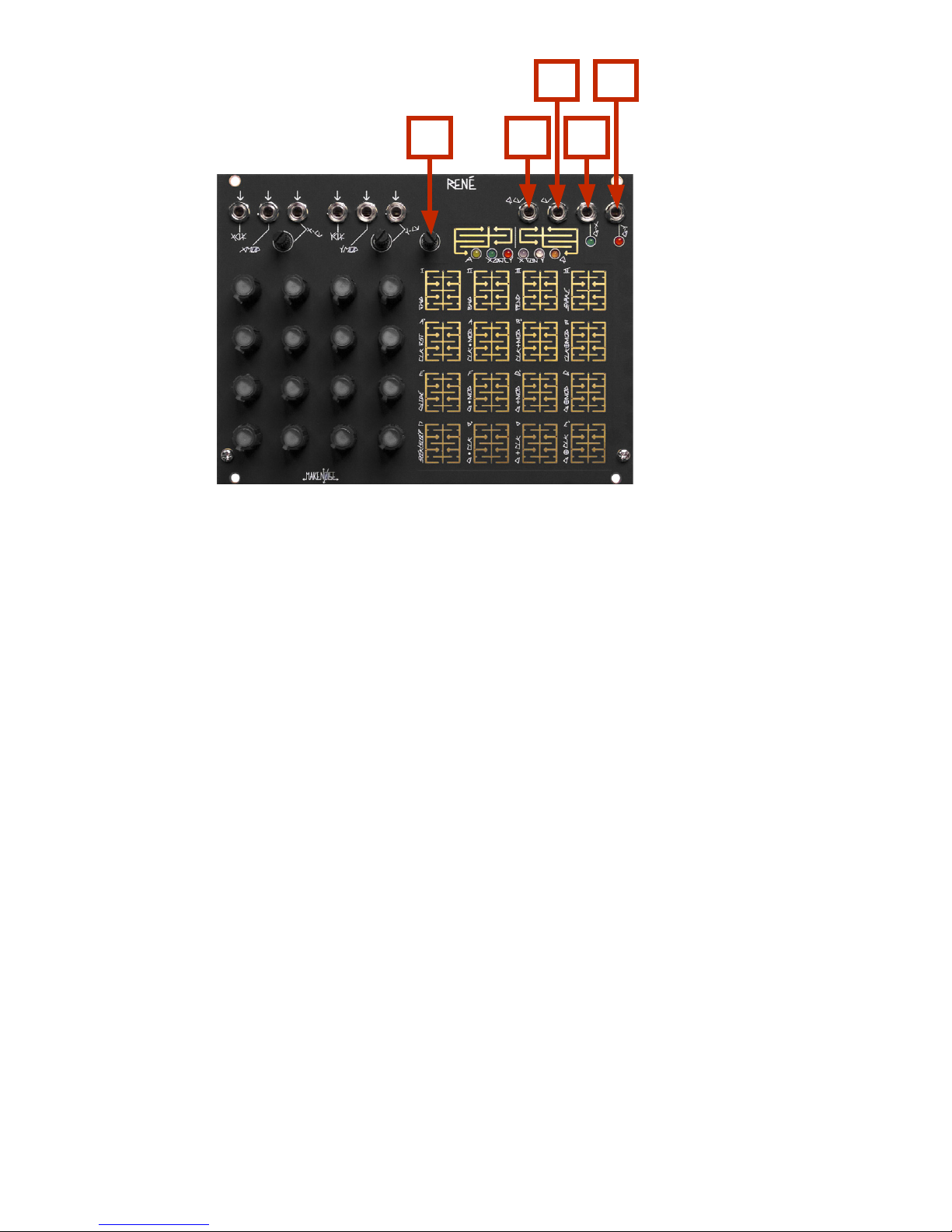
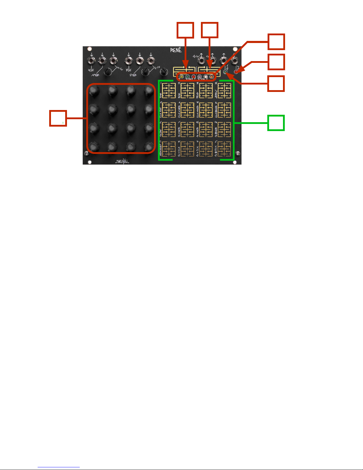
step sequencer from the shackles of linearity. Like the classic analog sequencers, there are only 16 steps on
René, each having an associated knob with which the note for that step is tuned. However, using René the
patterns are not limited to 16 steps in length because the path taken through those steps is, for all practical
purposes, innite. In fact, René does not “step” at all, but rather it maps coordinates to locations in a grid,
and because if this, it is possible to move in ways that you would never imagine a step sequencer to move.
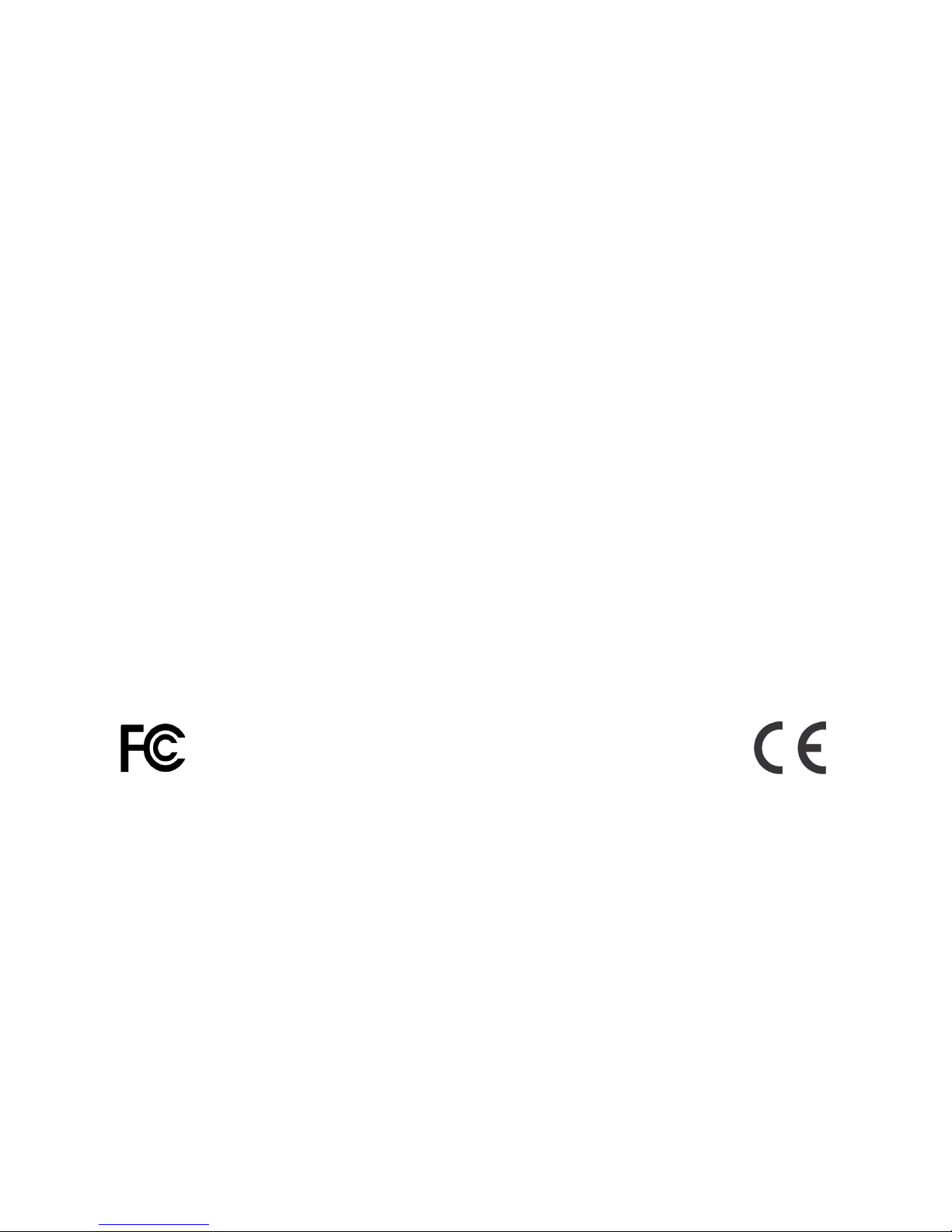
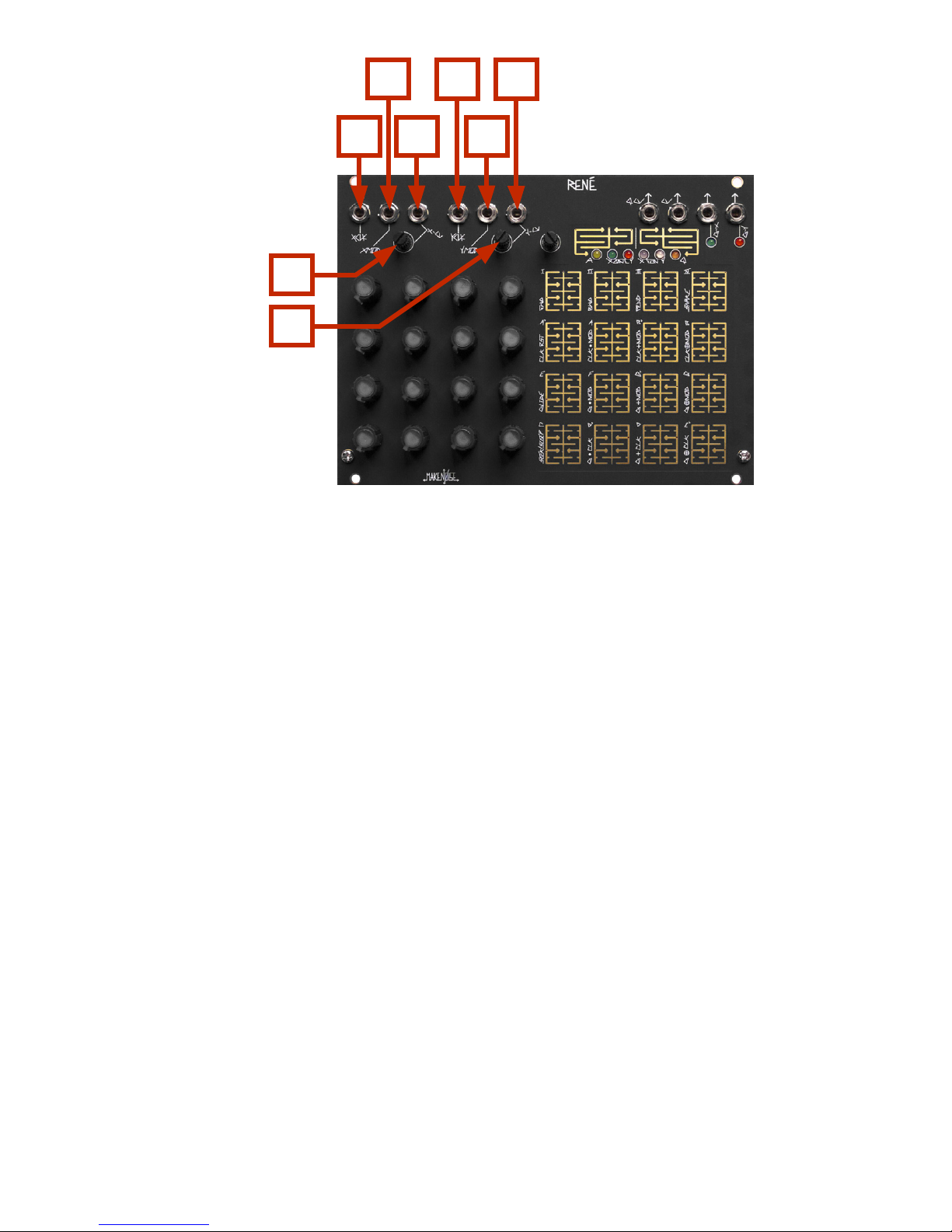
For this reason, we call the 16 steps on René “LOCATIONS,” and rather than one Clock input there are two;
one each for the X‐Axis, and the Y‐Axis.
The primary goal of this sequencer is to have a maximum amount of artist controlled musical variation, with
a minimum amount of data input. There are no menus, ALL editing is done real‐time, and thus, the
ProGraMming of René becomes a key performance element.
The basic concept for how René works: each
Axis is being driven by the corresponding clock and control voltages, to generate a number from 0 to 3.
These numbers together make up the coordinates for the next location that René will go to. For example,
if X hits 2 and Y is at 3, then René goes to location 14.
The concept is simple, but the results are madly complex, especially when combined with some of the other
math that René will do.

René Panel Controls
Inputs:
1. X-CLK Input: Clock/Gate signal (of width greater than .5ms and amplitude greater than 2.5V) applied
to this input drives the X-Axis Counter. If using MATHS to clock, then set Vari-Response to
LINEAR. When René counts Snake Style, X-CLK steps linearly through a stored set of
coordinates; it drives the sequence.
2. X-MOD Input: The state of this input (either HI or LO) further determines behavior of René depending
upon the selections made in the X-Fun PGM Page. For example, when CLK-RST is selected
under X-Fun a logic HI at this input will Reset the X-Axis Counter to 0.
3. X-CV Input: Control signal at this input generate a number that is added to the number generated by
the X-Axis Counter, to create the X coordinate. When René counts Snake Style, X-CV scans
linearly through a stored set of coordinates. X-CV is normalled to +5V so that with
nothing patched the attenuator acts as oset generator
4. X-CV Input CV Attenuator
5. Y-CLK Input: Clock/Gate signal (of width greater then .5ms and amplitude greater then 2.5V) applied
to this input drives the Y-Axis counter. If using MATHS to clock, then set Vari-Response to
LINEAR. When René counts Snake Style, Y-CLK selects stored coordinates set.
6. Y-MOD Input: The state of this input (either HI or LO) further determines behavior of René depending
upon the selections made in the Y-Fun PGM Page. For example, when Glide is selected
under Y-Fun a logic HI at this input will engage the glide function.
7. Y-CV Input: Control signal at this input generate a number that is added to the number generated by
the Y-Axis Counter, to create the Y coordinate. When René counts Snake Style, Y-CV
selects stored set of coordinates.. Y-CV is normalled to +5V so that with nothing patched,
the attenuator acts as an oset generator.
8. Y-CV Input CV Attenuator
1
2
3
5
6
7
8
4

10
11
12
13
9
René Panel Controls (cont’d)
Sensivity:
9. Touch Grid sensitivity control. To increase sensitivity, set the position 100% clockwise.
Outputs:
10. QCV: The Quantized Control Voltage for the currently active location will appear at this output. QCV
may also yield a Stored Quantized Voltage (if selected on Q Page), in which case the
corresponding location potentiometer is no longer “live.” Value: 4 octaves.
11. CV: An unquantized Control Voltage of the currently selected location will appear at this output. At
the CV OUT, the location potentiometers are always “live.” Value: 0 to 4.5V.
12. Gate X: This output reects the ProGraMming on the X-Gate Page. When René arrives at a location,
and the location is set to ON (lighted) at the X-Gate PGM Page, this output goes HI for duration
determined by the XCLK width and any ProGraMmed Logic Operations that Axis Clock or Gate.
When counting SNAKE style, the Gate output is always a skinny pulse (2ms) perfect for ringing
LoPass Gates. Value: 0V or +8V.
13. Gate Y: This output reects the ProGraMming on the Y-Gate Page. When René arrives at a location,
and the location is set to ON (lighted) at the Y-Gate PGM Page, this output goes HI for duration
determined by the YCLK width and any ProGraMmed Logic Operations aecting the Axis Clock or
Gate. When counting SNAKE style, the Gate output is always a skinny pulse (2ms) perfect for
ringing LoPass Gates. Value: 0V or +8V.

20
14
15
19
16
René Panel Controls (cont’d)
Interface:
14. CV ProGraMming Grid: Potentiometers used for ProGraMing. Contain Location LED’s to indicate
currently active Location(s).
17. PGM 1: [PRESS] to cycle through the ProGraM Pages
18. PGM 2: When in a ProGraM Page, [PRESS] to return to Play Mode. While in Play Mode, [PRESS] to latch
currently-held Locations.
20. Touch Grid: Used to select Locations for ProGraMming and latching.
Indicators:
15. G-Y LED: [FLASHES] to indicate Gate activity at the G-Y Output.
16. G-X LED: [FLASHES] to indicate Gate activity at the G-X Output.
19. ProGraM Page LED’s: Light when associated ProGraM Page is being accessed. All ProGraM LED’s will
[FLASH] to indicate storage is taking place.
17 18

Controls
4x4 CV Programming grid: Potentiometers sets Tuned Voltage for corresponding Locations, 0 thru 15.
4x4 touch grid: In PLAY mode, the touch pads may be used to set ACCESS in real time, eectively allowing
the performer to play the ACCESS parameter. In use, this means that René will go to only the locations that
the performer is touching. Additionally, touching and releasing a single location while René is PLAYing will
set a new start point, thus creating a variation on your sequence. With no Clocks patched to René, touching
any location on the Touch Grid will select said location, and the CV and QCV value is held until the next
location is touched, or a clock pulse is applied to either X-CLK or Y-CLK. This is useful for Programming or
Tuning Notes (with CV applied to VCO 1V/oct input, for example). In ProGraM Pages, the Touch Grid is used
select and deselect the various parameters available under each PGM Page.
PGM 1: This Touch Plate is used to cycle through the dierent ProGraM Pages. Each of the 6 ProGraM pages
has an associated LED which lights when selected. PGM1 returns to last selected PGM Page.
PGM 2: While PLAYing, this Touch Plate is used to Latch/Unlatch the steps held by the performer using the
4x4 Touch Grid. Once within the PGM Pages, the PGM2 touch is used to EXIT the PGM Pages and return to
PLAY. The PGM2 button is also used to save the default start‐up programming for René. To do this, make all
changes to all ProGraM Pages. Touch PGM2 and exit PGM Pages. Now, Touch and [HOLD] PGM2 until all
PGM LED’s blink.
Play
This is the primary state of mind in which René will exist. The Location Lights (within the Knobs) show the
Cartesian or Snake motion of the sequence through the grid. While in PLAY, the performer may usethe
touch grid to ProGraM ACCESS on the y, stop and hold the sequence at a particular note or set a new start
point. Touching PGM1 brings up the PGM Pages (see below). Touching PGM2 LATCHES locations currently
touched by the performer (if any). All of the PGM Page LEDs will light until PGM2 is touched again, at which
point the Latched pattern is no longer. Movement is always governed by the X-CLK and Y-CLK inputs. For
example, the performer cannot select a three step sequence in the Y direction if there is no Y clock signal
input. Touch and HOLD PGM2 for 2 seconds, and the current state of René (all programming) is saved as the
start‐up state.

ProGraM Pages
These pages give the performer real‐time control over the deeper processes within René, allowing real time
sculpting of the thought processes that drives the sequence.
ACCESS: the performer Grants ACCESS or Denies ACCESS to any of the 16 Locations in the Touch
Grid. If a Location is ON (lighted), the René will be able to map those coordinates. If a location
is OFF (not lighted), then René not be able to map those coordinates, and will either SEEK the
nearest possible location, or SLEEP (keep in mind, that René counts in it's sleep) until
mappable coordinates are conjured. Thus, ACCESS ProGraMming allows the performer to limit
a pattern to certain Locations.
X‐Gate: The performer may select/deselect which Locations in the 4x4 Touch Grid will generate a
gate at the G-X Output.
Y‐Gate: The performer may select/deselect which Locations in the 4x4 Touch Grid will generate a
gate at the G-Y Output output.
X‐FUN: At this Page the 4x4 Touch Grid is used to edit the behavior of the X‐Axis. For complete
details of X‐FUN’s features, please see appendix A.
Y‐FUN: At this Page the 4x4 Touch Grid is used to edit the behavior of the Y‐Axis. For complete
details of X‐FUN’s features please see appendix A.
Q: This PGM Page gives the performer the ability to dene the Scale to which the QCV will be
quantized. The performer is also given four slots to store Scales and the Voltages
Programmed at the 16 Locations. For complete details of the Quantization Edit mode, please
see appendix B.

APPENDIX A
(X‐FUN and Y‐FUN)
Counting:
FWD: for every Clock Pulse, associated counter advances one digit. 0, 1, 2, 3. After 3, counter returns
to 0.
BWD: for every Clock Pulse, associated counter recedes one digit. 3, 2, 1, 0. After 0, counter returns to
3.
PEND: for every Clock Pulse, associated counter advances from 0, 1, 2, 3 and then recedes 2, 1, 0. The
motion is like that of the pendulum of a clock.
Snake: When selected, the X‐CLK and X‐CV scan linearly through one of 8 sets of coordinates René has
memorized (see Appendix C), the result is a more predictable, snake like movement through the 16
Locations. The memorized coordinate sets are selected via pulses at the Y‐CLK input and/or the Y‐CV
input and associated pot. Since the Y‐CV is normalled to +5V, you may manually select a coordinate
set by adjusting the Y‐CV attenuator. Gates will be generated per axis, each time René moves along
corresponding axis. So for example, moving from Location 2 to Location 3, G-X will pulse. Moving
from Location 3 to Location 4, G-Y will pulse.
CLK RST: When selected, a pulse at the X‐MOD input will reset the X Counter to 0, which is the left most
column (coordinate 0, Y). A pulse at the Y‐MOD input will reset the Y Counter to 0, which is the
bottom most row (coordinate X, 0). If all of the zero coordinates are ACCESS DENIED by either
ProGraMming or TOUCH ACCESS, and both X and Y Axis are Reset, then René will be forced to stop,
since it has been Reset to a Location where there is no path out.
In Snake Mode, a pulse at the X-MOD input will reset to the last stage touched. A pulse at the Y-MOD
input will Reset the Snake pattern selection.
Glide: When selected under X‐Fun and/or Y‐FUN, the sequence will Glide between each step along the
X-Axis when a gate is present at the X‐MOD input. To use Glide, patch the Gate or Clock you wish to
set glide on/o to one of the two MOD inputs. If you are using X-MOD, then go to X‐FUN and set
Glide to ON. If you are patched to Y-MOD, then go to Y‐FUN in order to set Glide to ON. The Glide
function is not Axis independent, and only one of the two axis needs to be used for programming
Glides.
Seek/Sleep: When OFF (not lighted) René SEEKS, when ON (lighted) René SLEEPS. This refers to how René
nds the next ACCESSible Location. If you have at least one Location set "Access Denied," you will
hear the eect.
When René is plotting coordinates on the grid and it comes to a Location that has No ACCESS
(ACCESS Denied) it will nd ACCESS in one of two ways:
Seek: With this behavior, René is restless. If René comes to a Location that is ACCESS Denied, it looks
for the next available Location and goes immediately to this location, and FAST.
Sleep: With this behavior, René is more relaxed. If René nds a Location that is ACCESS Denied, it just
kicks back and continues to count until it produces coordinates for a Location that may be
ACCESSed.

Musically speaking, Seek moves more, and Sleep will rest more. Using Sleep and ProGraMming Access
and Gates, it is possible to create rests, pauses and etc...
LOGIC OPERATIONS
There are 3 rows of the logic processing. CLK by MOD, Gate by MOD and Gate by Opposing CLK.
With the Clock Logic Ops (locations 9, 10, 11) the MOD input is AND, OR, XOR against the CLocK and the
result drives the counter for the associated Axis.
With the Gate Logic Ops (locations 5, 6, 7) the MOD is AND, OR, XOR against the CLocK and the result
drives the gate programming logic (X Gate or Y Gate pages). The LAST part of the chain is the GATE ON/
OFF, thus giving Gate ProGraMming top level control in the grand scheme of René. When you want a
particular location to NOT generate an event, you turn off the Gate and there will be NO event.
Truth Tables:
(NOTE: 0 = FALSE = OFF, 1 = TRUE = ON)
For CLK by MOD logic operations the results apply to both the movement of the sequence and the
associated gate outputs. For Gate by MOD logic operations the results apply only to the associated gates
outputs. It is easy to experiment with different logic operations, so do not be shy. In some cases the
results are wonderfully jumbled, while in others, they are barely noticeable. One parameter that has a
great deal of bearing on the outcome of these logic processes is Gate Width of the incoming CLocK and
MOD signals.
A
B
AND AB
ABOut
0
1
00
00
100
1 1
1
A
B
OR AB
ABOut
0
1
00
01
101
1 1
1
A
B
XOR AB
ABOut
0
1
00
01
101
1 0
1

A
LOC. 10
B
LOC. 11
B
LOC. 4
E
LOC. 5
F
LOC. 6
G
LOC. 7
G
LOC. 3
E
LOC. 2
D
LOC. 1
D
LOC. 0
C
LOC. 9
A
LOC. 8
III III IV
LOC. 14 LOC. 15
LOC. 13LOC. 12
ACCESSES STORED QUANTIZED
VOLTAGES, SQV
APPENDIX B
Stored Quantized Voltages
While at the Quantize Page, to store all 16 Voltages as set by the potentiometers and the ProGraMmed Scale
as set by touch grid Locations 0 thru 11, touch and hold either Location 12, 13, 14, or 15 until all 6 PGM LEDs
ash. When Locations 12, 13, 14, or 15 is ON while accessing the Q Page, the QCV Out will produce voltages
per location as well as the scale in which they were initially stored. The scale may still be edited on the y,
but the knobs will no longer be “live” while any one of the Stored Quantized Voltage (SQV) sets is in use. To
turn OFF the Stored Quantized Voltages set, touch the location of the active set, thus toggling the SQV to
OFF.
With the scale AND the Voltages you have programmed stored, you eectively have two channels of Control
Voltages. The most common use would be to apply the QCV to 1V/ Octave input on your VCO, Program
your scale and the notes you want to use in your composition. Store those to one of the 4 locations (12, 13,
14, 15). If you want variations, then store those variations to the remaining locations. Now, patch the CV
out (un‐Quantized) to a timbre control, such as FM Index, wave shape, or lter resonance. Because your
QCV is using the Stored Quantized Voltages to drive the VCO, the un-Quantized CV out is now independent,
as you are able to turn the knobs to program new voltages to controltimbre without changing the notes
pattern driving your VCO. Apply the Gate outs to EG/ VCA combo or Low Pass Gate, and you have full
control of one voice.
TURN ON/OFF VALUES
TO ADJUST ACTIVE SCALE

APPENDIX C
Snake: Memorized Coordinate Sets:
These drawings illustrate the SNAKE like paths that René travels, reading coordinates from memory.
Conceived and Illustrated by yerpa58.

Appendix D: Introduction to Logic Tutorial
(For more information, watch “Rene Logic Walkthrough” on YouTube)
This section will provide a short walkthrough of the Logic portions of the X-FUN and Y-FUN pages. These
functions all take place "after" the ACCESS, X-GATE, and Y-GATE pages, so you can totally disable particular
stages' Locations and Gates as an "over-ride" to the logic section. The ACCESS page can also be immediately
overridden at any time by touching the Location Grid. This means that for each axis, there is a hierarchy:
- Touch
- Access Page
- Gate Page
- Clock Logic
- Gate Logic
- Opposing Clock Logic
To get started, activate all the locations on the ACCESS page and the X-GATE and Y-GATE pages. On the
X-FUN and Y-FUN pages, and turn o all of the logic functions and make sure only Location 12 (FWD) is
active, so that the Rene operates in Cartesian Mode. Now, you have an "init" state, as seen
here
.
Now, patch a clock source into the X-CLK input. Each clock pulse steps the Rene forward along the X-Axis
and outputs a gate via the G-X Output.
The logic functions exist so that you can alter the two behaviors (Movement along the X-Axis and G-X
Gates) independently. Specically, it uses the COMBINATION of the signals at the X-CLK and X-MOD
inputs to create new behaviors.
On the X-FUN page, activate Location 9, AND:
This is AND for the clock. Keep the clock patched to the X-Clock input. You'll see that the sequence is no
longer advancing. Patch an Oset (for example, a Tuned Voltage from the Pressure Points or the EOC from a
non-cycling Function/MATHS Ch4) to the X-MOD input. You’ll notice the X-Axis will begin to advance again;
however, only as long as the Gate stays high. AND logic means a signal needs to be present in BOTH inputs
for a signal to appear at the output. In this case, X-CLK and X-MOD are the two inputs and the "output"
refers to Rene X-Axis advancement; however, the Rene does re Gates as well, which are available at the G-X
Output. (Note: the Rene CAN advance without ring a Gate, but we’ll get to that shortly.)
Location 10 activates OR for the X-CLOCK:
Activate it, and EITHER input will advance the Rene to the next X-Axis Location-- including if both are active.
For example, if you were to patch two independent clock sources to the X-CLK and X-MOD inputs, the Rene
would advance to the next X-Axis location whenever either clock goes “high.” It is important to note, if one
clock begins while the other clock is already HIGH, the Rene will NOT advance, as there is no state change:
the output is already high and so it remains high.

Introduction to Logic Tutorial (cont’d)
Location 11 activates XOR (exclusive or):
A clock patched to either the X-CLK or X-MOD input will advance the Rene to the next X-Axis Location;
however, if both are high at the same time, the Rene does not advance. With this XOR activated, try running
a low-frequency square wave into the X-CLK input for steady clock advancement while periodically sending
a wide Gate signal to the X-MOD input in order to "invert" the clock.
The next row down contains the same three logic functions, but they only aect the Gates that appear at the
G-X output-- not the Rene’s movement/clock.
For example:
Location 5 activates G AND MOD for G-X:
Now, the signals at the X-CLK and X-MOD inputs BOTH need to be high in order to cause a Gate to appear at
the G-X Output. Notice, even when the Rene advances to the next X-Axis Location, no Gate appears at G-X
until there is positive signal present in the X-MOD input as well.
Therefore, with a combination of the CLOCK and GATE logic rows, you can have X-Clock Advancement
and X-Gates at G-X somewhat independent from one another, yet always related to some
combination of the signals patched to the X-CLK and X-MOD inputs.
The nal row (Locations 1, 2, and 3) contains GATE by OPPOSING CLOCK logic. This adds one more stage of
logic operations to the G-X Output Gates, deriving the output state from the result of the two rows above as
well as the Y-CLK Input.
The Y-FUN Page contains the same logic functions; however, they control movement along the Y-Axis and its
associated Y-CLK and Y-MOD inputs, as well as the G-Y output. The bottom row (Locations 1, 2, and 3)
contains the same GATE by OPPOSING CLOCK logic as before, using the X-CLK Input to derive the output
state.

Patch Example:
Voltage Controlled Raga:
www.youtube.com/watch?v=DHf4q7pehtg
Adjust Rene’s XCV input attenuator slowly up from 0% in order to gradually destabilize the sequence.
Variation:
1. Turn Fold CCW and patch one of Rene’s Gate Outputs to the DPO’s STRIKE Input.
Toggled Sequencing Concept
(No Sound as Depicted)
(Adjust to Taste)
(Adjust to Taste)
Rene will only sequence along each axis when the associated touchplate is pressed.

Patch Example:
Concept: Non-Linear Quantization
(No Sound As Depicted)
www.youtube.com/watch?v=BnoFMimnK6s
Turn Stages On/O
to control scale
Variation:
Patch MATHS EOC Output to Rene Y-CLK Input in order to switch snake patterns aftern each MATHS
Function/Envelope cycle.
Concept: “Arpeggiation” of a 4-step Sequence
(No Sound as Depicted)
For best results, tune each Y-axis column to a chord using the knobs and the Q page.
( Adjust to Taste )
Level of
Arpeggiation
Quantization Level(s)

Patch Example:
Concept: Cogito Ergo Sum Ergo Cogito Ergo Sum Ergo Cogito:
(Now Sound As Depicted)
www.youtube.com/watch?v=4aBjM08cndA
This feedback patch will cause Rene to jump locations every time it sends a CV value much greater
than zero. Many nonlinear patterns await discovery. A “cluster” of higher CV values will cause
extended sudden movement. “Eddies” can be created by setting several adjacent knobs to low
values. Dierent clock sources in the X and Y clock inputs can create variation in the patterns.
Variation:
Recall a stored sequence on the Q page to allow constant reconguring of the knob settings for the
feedback patch but with the same “melodic” values from the QCV output.
Process CV
To Taste
Other manuals for Rene
1
Table of contents
Other Make Noise Recording Equipment manuals

Make Noise
Make Noise 7U 4 ZONE CV BUS CASE User manual

Make Noise
Make Noise MATHS User manual

Make Noise
Make Noise 0-CTRL User manual

Make Noise
Make Noise DPO User manual

Make Noise
Make Noise RxMx User manual

Make Noise
Make Noise XPO User manual

Make Noise
Make Noise PHONOGENE User manual

Make Noise
Make Noise Rene User manual

Make Noise
Make Noise modDemix User manual

Make Noise
Make Noise MATHS User manual