Makeblock Airblock User manual

D1.4.6_7.40.4602
www.makeblock.com
Makeblock Co., Ltd.
Address: 4th Floor, Building C3, Nanshan iPark, No.1001 Xueyuan Avenue,
Nanshan District, Shenzhen, Guangdong Province, China
@Makeblock

Modular&Programmable Drone
USER MANUAL

P02
P03
P04
P05
P06
P10
P12
P18
P27
P30
Software Download
Parts List
Introduction to Main Control Module
Introduction to Battery
Introduction to Power Module
Introduction to Stickers
User Guide to Aircraft Mode
User Guide to Hovercraft Mode
User Guide to Custom Mode
FAQs
Table of Contents
·Operating Environment ·Warning
·Installation Steps ·Control
·Operating Environment •Warning
·Installation Steps ·Control
·Operating Methods ·Operating Environment
·Warning ·Programming

02
Software Download A tablet or smartphone is required to control the Airblock.
Download from App Store
Download from Ocial Website
Search "Makeblock" and install the application from app store.
http://learn.makeblock.com/en/software/
Login to download the corresponding version.
System and Device Requirements
For iOS Devices: Requires iOS 9.0 or later versions. Compatible with iPhone5, iPad mini, iPad
3 or later models. For Android Devices: Requires Android 4.3 or later versions.
Apple, the Apple logo, iPad and iPhone are trademarks of Apple Inc, registered in the U.S.
and other countries.
App Store is a service mark of Apple Inc.
Android and the Google logo are trademarks of Google Inc.

03
Parts List
Main Control Module
Power Modules Hovercraft Base Protective Cover
Battery Charger
Charging
Cable

04
The main control module includes 6 power module plug-
in sockets, 3 LEDs, an ultrasonic sensor, a barometer, a
gyroscope, Bluetooth, a microcontroller chip, etc.
Ultrasonic sensor is used for distance measurement. Works
together with barometer to measure height change of the
aircraft.
LED works as power supply indicator. Brightness and color is
adjustable through programming.
The following are built-in sensors:
Barometer can sense height changes.
Gyroscope can sense position and orientation of the main
control module.
Bluetooth module can establish connection with tablets or
smartphones. Application program can read the real-time data
collected by sensors.
6
5
Front View
Back View
LED
Ultrasonic Sensor
Plug-in Socket
Battery
Compartment
User Guide to Aircraft Mode

05
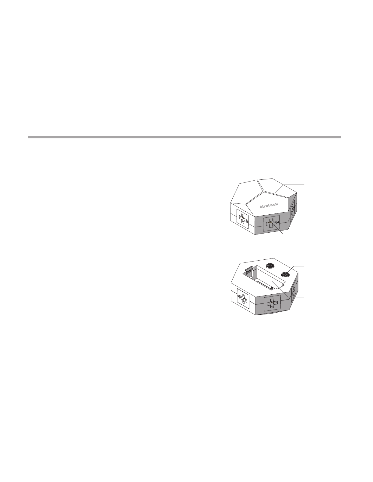
Airblock does not have a power switch. When a fully charged
battery is inserted into the main controller, the controller
automatically enters standby mode.
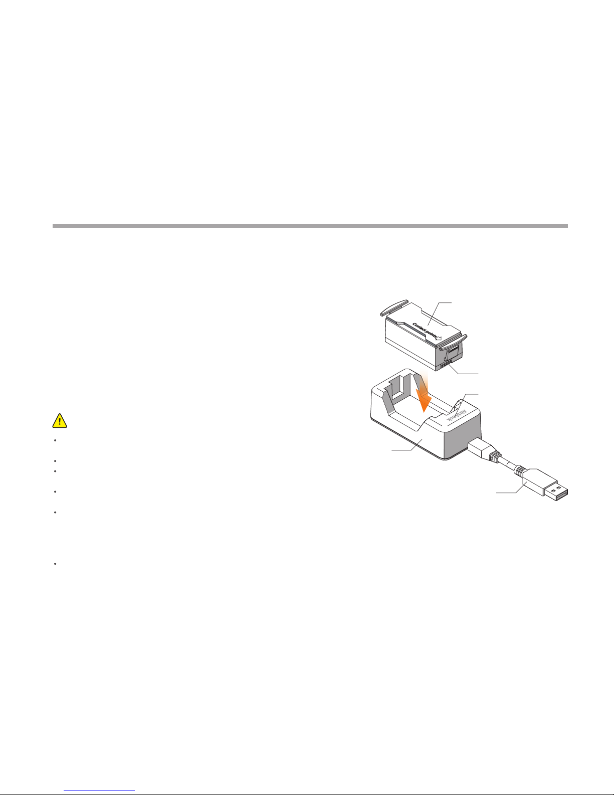
When inserting battery into main control module or battery
charger, please ensure that the contact points are placed in the
correct direction.
A red light indicates that charging is ongoing. A green light
indicates that the battery is fully charged.
Warning:
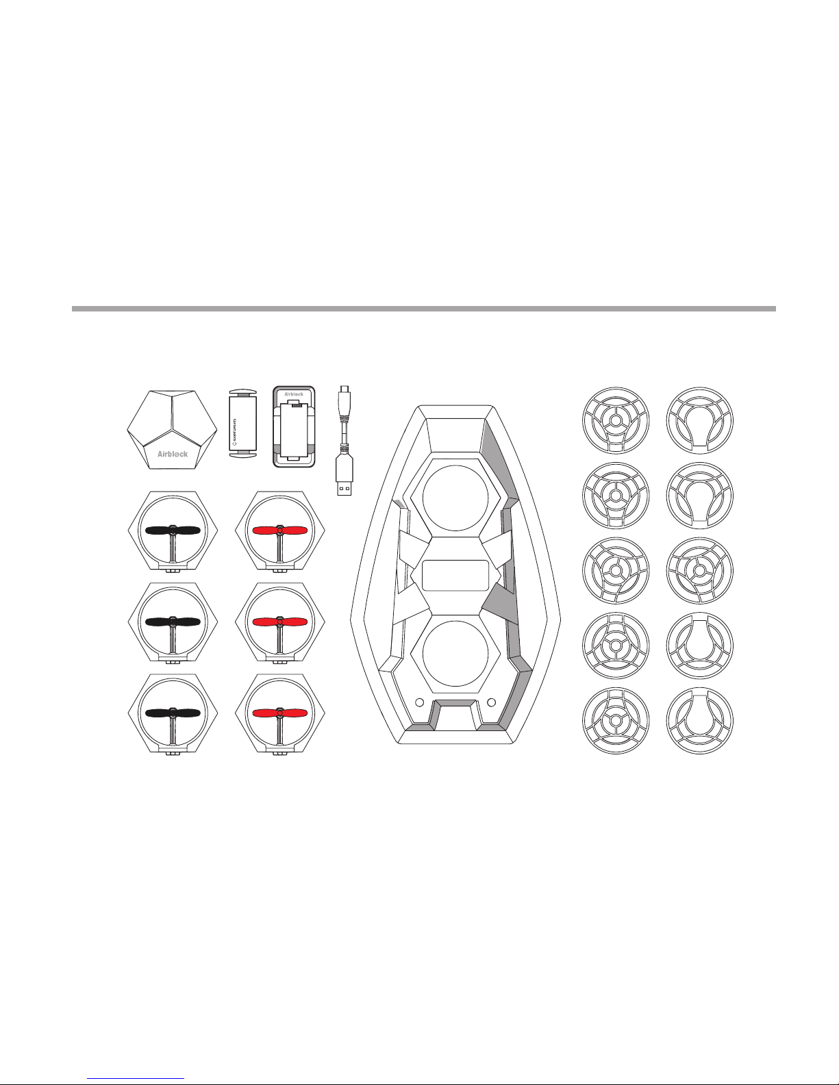
USB Cable (5V input)
Battery
Battery Contact Points
LED
Charger
Battery
If unused for an extended period, battery should be removed from the main control module,
and charged for half an hour before safekeeping to prevent damage due to overdischarging.
Do not charge the battery for more than 12 hours.
Do not use battery in high temperature or high humidity environment. Battery failure and
explosion may be cause by battery impact.
Electric wires, plugs, cases and other assembly units must be checked regularly whether they
are damaged or not. Do not use it if there is any damage until it has been fully repaired.
Battery types which can be used: Airblock special rechargeable lithium battery.
a. Rechargeable battery must be used under adults' supervision.
b. Rechargeable battery should be removed from the product before charging.
c. The battery should be put in with the correct polarity.
d. Exhausted battery should be removed from the main control module.
Power terminal shall not short-circuit.

06
Introduction to structure
The Power Module includes a motor, a propeller, a plug, a
frame, etc.
LED is installed on the frame. LED lights up when the motor
is activated.
LED on aircraft front power module and foot pad are red.
Foot pads on other power modules are black. LED as
indicators are green.
Frame
Foot Pad
Motor
EPP Protective Ring
Propeller
Plug
Power Module

07
Introduction to Operating Principles
In order to oset the self-rotation of the aircraft, the
propellers are classied in red (counter-clockwise
rotation) and black (clockwise rotation). Motors are also
classied as clockwise and counter-clockwise rotation.
After connecting to main control module, the motor
starts spinning and pushes air downwards to generate an
upward thrust.
Direction of thrust
Direction of air current Direction of air current
Direction of thrust
Clockwise Rotation Counter-clockwise
rotation
Power Module

08
Standard Angle
90°
180°
270°
Installation Angle
Each power module may be installed onto its
corresponding port on the main control module
at 4 dierent angles.
Power Module

09
Port Numbers
The power modules of red propellers are connected to
Ports 1, 3, 5 respectively, with the front module to Port 1.
Connect the power modules of black propellers to Ports
2,4,6.
Power Module

10
Stickers
Power Module StickersFuselage Stickers Hovercraft Stickers

11
Power Module Stickers:
Attached to power module side in order to distinguish the
direction of Airblock during ight.
It is recommended to attach a red sticker to the aircraft
front power module (Position 1) and a green sticker to the
black propeller power module (Positiotn 4). Other power
modules do not need stickers.
There are 3 dierent styles of stickers -- you can choose
accroding to your favor.
Stickers

User Guide to
Aircraft Mode

13
Warning:
User Guide to Aircraft Mode
Space larger than 3m×3m×3m is recommended for indoor ying.
Land: soft surfaces such as carpets and grass may cause interference to the ultrasonic sensor. It is recommended to take o from hard
and at surfaces.
Water: do not start or y the aircraft over water to prevent accidental falling into water, which can cause short circuit and re damage
to the machine.
Outdoors: a windy environment may interfere the aircraft's normal ight.
Before starting, make sure each module is assembled correctly and the protective cover is removed. The protective cover could
aect the airow and aircraft takeo can be interfered. Place the aircraft on an open ground. Ensure no obstacles within a two-meter
radius.
Shutting down power on Makeblock App during ight can cause sudden drop to the aircraft. This may damage the equipment.
Aerobatic ight needs a lager space in order to aviod collisions.
High speed rotating motors and propellers may cause injury. Please keep a safety distance from the aircarft before operating Airblock.
Dust, hair, fur, or water trapped in Airblock may result in motor malfunction or damage to electronic parts.
Operating Environment

14
User Guide to Aircraft Mode
If the front module is installed improperly, the direction of ight
can not be controlled properly.
Warning:
Installing the aircraft front power module
Install aircraft front power module with red foot pad onto
Port 1 of the main control module.
Installation Step 1

15
Install other power modules
Install the remaining power modules in sequence
onto the main control module.
Installation Step 2
User Guide to Aircraft Mode

16
Direction of battery
contact points
Battery Installation
After a fully charged battery is inserted, Airblock will be
automatically turned on and enters the standby mode.
The LED on the main control module top will display a
white light. When Bluetooth is successfully connected,
the light in front will turn red, and the light at rear will
turn green.
Installation Step 3
Before taking o, please ensure Airblock has its top
facing upward and Airblock is placed on a at ground.
The picture on the right shows the situation when
Airblock has its bottom facing upward.
In Aircraft mode, the protective cover must be
removed.
Warning:
User Guide to Aircraft Mode

17
Control
Step 1
Follow the instructions on the rst page of User Guide to download and install the application.
Open the Makeblock application and move the tablet or smartphone close to the running
Airblock, Bluetooth connection should be paired.
Step 2
Enter the control interface after successful connected. (Note: interface or icons may vary after
software updates. Please follow the interface of the latest version. This instruction manual is
for reference purpose only.) Follow the procedures on the New User Guide to familiarize with
the functions of dierent keys and learn how to use the Airblock.
User Guide to Aircraft Mode

User Guide to
Hovercraft Mode
Other manuals for Airblock
2
Table of contents
Other Makeblock Drone manuals