Maker Factory MF-4992453 User manual

Operating Instructions
Hexapod Robobug Complete Set
Item no. 1664151

2
Table of Contents
Page
1. Introduction...........................................................................................................................................................................................................................4
2. Explanation of symbols.........................................................................................................................................................................................................4
3. Intended Use ........................................................................................................................................................................................................................4
4. Package Contents ................................................................................................................................................................................................................5
5. Product Description ..............................................................................................................................................................................................................5
6. Features ...............................................................................................................................................................................................................................6
7. Safety Instructions................................................................................................................................................................................................................7
8. Required accessories...........................................................................................................................................................................................................8
9. General notes.......................................................................................................................................................................................................................9
10. Preparatory work ................................................................................................................................................................................................................10
a) Application of the screw locking lacquer .......................................................................................................................................................................10
b) Ball bearings and cylindrical pins..................................................................................................................................................................................10
c) Power Supply................................................................................................................................................................................................................ 11
d) Installationofthesoftwareandrmware......................................................................................................................................................................11
11. Transferring the Firmware ..................................................................................................................................................................................................12
a) Installing the driver........................................................................................................................................................................................................12
b) Install Arduino IDE.........................................................................................................................................................................................................12
c) Setting up Arduino IDE..................................................................................................................................................................................................12
12. Preparing the leg servos for installation .............................................................................................................................................................................15
13. Assembling the mechanical parts.......................................................................................................................................................................................18
a) Mounting servos............................................................................................................................................................................................................18
b) Mounting of bearings.....................................................................................................................................................................................................20
c) Mounting the servo disks ..............................................................................................................................................................................................22
d) Mounting the spacer......................................................................................................................................................................................................24
e) Mounting the servos on the top plate............................................................................................................................................................................25
f) Mount bottom plate .......................................................................................................................................................................................................27
g) Mounting the Receiver and Hexapod Robot Board.......................................................................................................................................................29
h) Mounting the legs..........................................................................................................................................................................................................32
i) Laying the cables ..........................................................................................................................................................................................................35
j) Installing the battery......................................................................................................................................................................................................39
k) Mounting the rubber feet...............................................................................................................................................................................................40
l) Setting jumpers .............................................................................................................................................................................................................40
14. Transferring the Firmware ..................................................................................................................................................................................................41
15. Controlling with the Gamepad ............................................................................................................................................................................................42
16. Calibrate legs......................................................................................................................................................................................................................44
17. Using user boards ..............................................................................................................................................................................................................47
18. Demo Programmes ............................................................................................................................................................................................................50
19. Overview of the connections and components of the robot board .....................................................................................................................................53
20. Schematic system overview (block diagram) .....................................................................................................................................................................55
21. Pan unit ..............................................................................................................................................................................................................................56
22. Pin assignment of the user boards.....................................................................................................................................................................................57
23. Parts list..............................................................................................................................................................................................................................58
24. FAQ ....................................................................................................................................................................................................................................63
25. Cleaning .............................................................................................................................................................................................................................64
26. Declaration of Conformity (DOC)........................................................................................................................................................................................64

3
Page
27. Disposal..............................................................................................................................................................................................................................64
a) Product..........................................................................................................................................................................................................................64
b) Batteries/Rechargeable Batteries .................................................................................................................................................................................64
28. Technical Data....................................................................................................................................................................................................................65
a) General information.......................................................................................................................................................................................................65
b) Control electronics ........................................................................................................................................................................................................65
c) Gamepad ......................................................................................................................................................................................................................65
4
1. Introduction
Dear customer,
Thank you for purchasing this product.
This product meets the requirements of current European and national guidelines.
We kindly request the user to follow the operating instructions to preserve this condition and to ensure safe operation!
This user manual is part of the product. It contains important information on starting up and handling the device. Bear this in mind if you pass this
product to a third party.
For this reason, keep these operating instructions for future reference!
All names of companies and products are the trademarks of the respective owners. All rights reserved.
If there are any technical questions, please contact:
International: www.conrad.com/contact
United Kingdom: www.conrad-electronic.co.uk/contact
2. Explanation of symbols
An exclamation mark in a triangle indicates important instructions in this operating manual which must be adhered to.
Thearrowsymbolindicatesspecictipsandadviceonoperation.
3. Intended Use
The "Hexapod Robobug" complete set is solely designed for training, research and private use in the hobby or model construction area and the operating times
associated with it.
The product is not a toy and should be kept out of reach of children under 14 years of age.
The product is aimed at advanced users who already have experience with Arduino and the programming language C/C ++ and also in electronics as well as
in the construction of mechanical kits.
The product must not get damp or wet! The electronics are designed for operation at an ambient temperature between 0 °C and +40 °C. The electronics are
designed for use in a wide range of applications.
Observe all the safety instructions in these operating instructions. They contain important information regarding the handling of the product. You are the sole
responsible for the safe operation of the Hexapod Robobug complete set!
Mechanical components as well as servo motors are subject to natural wear and can wear during long operating times. The servos can be reordered as spare
parts. The servo motors have a high cycle stability of up to 100,000 cycles. However, the Robobug is not designed to carry out permanent movements. The
motors in the servo require a break of at least 10 minutes after a longer run (about 10 minutes of continuous movement) in order to cool down. This ensures
a long service life.
If you use the product for other purposes than those described above, the product may be damaged. Moreover, improper use involves risks such as short-
circuits,re,electricshocks,etc.Pleasereadtheoperatinginstructionscarefullyanddonotdiscardthem.Pleaseincludetheseoperatinginstructionswhen
you pass the product on to a third party.

5
4. Package Contents
• Hexapod Robobug Mechanical Kit
• 18x Servos
• Hexapod Robot Board
• Gamepad for control
• Small parts (e.g., jumpers, battery plug XT30)
• Quick guide
Latest Operating Instructions
Download the latest operating instructions via the link www.conrad.com/downloads or scan the QR code shown here. Follow the instruc-
tions on the website.
Ontheproductwebsiteyouwillndallsampleprogrammes,rmwareupdatesandfurtherinstructionsforextensions.
5. Product Description
A running robot for beginners as well as experienced developers: With the "Hexapod Robobug" complete set, consisting of electronics, mechanics and digital
high-performance servos, you can build your own Hexapod running robot and enter the exciting world of robotics!
The"HexapodRobobug"completesetistheidealbasisforenteringtheeldsofelectronics,mechanicsandprogramming:itenablesalargenumberofexten-
sions by using additional user boards such as Arduino, Raspberry Pi or NodeMCU and offers space for many additional components.
The robot is designed in such a way that it can be controlled without programming using the controller supplied, similar to an RC model. Thanks to its expand-
abilityandexibility,therobotisperfectforhobby,research,schools,educationandtrainingandencouragesindependentdevelopmentandexpansion.
Figure 1
(*) Not included in the delivery:
The 3D print data of the Pan & Tilt unit and the required components can be found on the product's website. The product also requires a rechargeable
battery and a suitable charger.

6
6. Features
• Simple construction
• Easy programming with Arduino™ (Arduino™ library available)
• Firmware based on Arduino™
• Onboard locomotion controller ATmega2560 for leg control (Arduino™ MEGA compatible)
• 18x high performance digital servos with metal gear, double ball bearings
• High-quality aluminium and plastic parts
• Legs with double ball bearings
• Control via gamepad (included in delivery) and user board commands
• Easily accessible connections for your own expansions
• Serial data connection between user board and locomotion controller
• Compatible with the following additional boards: Arduino, NodeMCU, SBC (e.g., Raspberry Pi)
• USB programming interface for Locomotion controller
• Loudspeakerwithamplierforsoundoutput
• MicroSD card reader
• Infrared receiver
• Freely usable buttons
• Power management
• I²C Seeed Grove connector for extensions
• Automatic level adjustment for 5 V and 3.3 V user boards
• Versatile expandability thanks to open architecture and open source software
• Complete kit to set up the robot (batteries, rechargeable batteries and charger not included)

7
7. Safety Instructions
Please read the operating instructions carefully and pay particular attention to the safety instructions. We do not assume liability for any
injuries/material damages resulting from failure to observe the safety instructions and the information in these operating instructions
regarding the proper use of the product. Furthermore, in such cases, the warranty / guarantee will be null and void.
Dear customer,
These safety instructions are not only for the protection of the product, but also for your own safety and the safety of other people. Therefore, please
readthischapterverycarefullybeforeusingtheproductforthersttime!
• The product is aimed at advanced users who already have experience with Arduino and the C/C ++ programming language as well as in electronics
andintheconstructionofmechanicalkits.Ifyoudonothavesufcientexperience,pleasecontactanexperienceddeveloper,alocalbuildersclub
or our support.
• Forsafetyandapprovalreasons,unauthorisedconversionand/ormodicationoftheproductbeyondwhatisdescribed,isnotpermitted.
• The product is not a toy. Keep out of the reach of children and pets.
• Do not carelessly cast aside the packaging material. It may become a dangerous plaything for children.
• Protect the product from extreme temperatures, direct sunlight, strong vibrations, high humidity, moisture, combustible gases, vapours and solvents.
• Never expose the product to mechanical stress.
• When connecting the servos, other components and their connecting cables, ensure that the contacts are secure. Loose or wobbly connectors may
cause interference or damage.
• If soldering is required, be sure to avoid short circuits occur during soldering. Before you perform a soldering operation, all parts must have zero
potential.
• To avoid short circuits, make sure that components or solder contacts do not come into contact with metal parts, when installing the board. Short
circuits will ruin the product and void the warranty!
• If safe operation is no longer possible, take the device out of service and secure it against unintended use. Safe operation is no longer possible, if
the product:
- shows visible damage,
- no longer functions properly,
- has been stored under adverse ambient conditions for an extended period of time or
- has been exposed to considerable strain during transport.
• Please handle the product with care. The product can be damaged if crushed, struck or dropped, even from a low height.
• If you have doubts about how the equipment should be operated or how to safely connect it, consult a trained technician.
• Maintenance, adjustment and repair work should only be carried out by an expert or a specialised workshop.
• If you have any questions that are not answered in these operating instructions, please contact our technical customer service or other profession-
als.

8
8. Required accessories
• NiMH battery; 5 cells, min. 3700 mAh (e.g., Conrad item no. 1784857)
• Charger (e.g., Conrad item no. 1413029 or 1413030)
• Adapter cable XT30 (e.g., Conrad item no. 1785258)
• Batteries (2x AAA/Micro) (e.g., Conrad item no. 658010)
• Screw locking (e.g., Conrad item no. 826389)
• Mini-USB cable (e.g., Conrad item no. 1365369)
Optional:
• Servo for Pan unit * (e.g., Conrad item no. 1762878)
• Servo for tilt unit * (e.g., Conrad item no. 1762877)
• Arduino UNO (e.g., Conrad item no. 191789)
• Screw locking (e.g., Conrad item no. 1613301)
* The Pan & Tilt unit is the head mechanism (see Figure 1) and can optionally be printed on a 3D printer.
Required tools and material:
• Small side cutter (electronic side cutter)
• Scissors
• Open-end wrench SW 5.5 mm
• Open-end wrench SW 4 mm
• Phillips screwdriver PH1
• Phillips screwdriver PH2
• Hexagon socket 6 mm
• Hexagon wrench 1.5 mm
• Hexagon wrench 2.5 mm
• Screw locking (medium strength) e.g., LOCTITE®243 (Conrad item no. 1370555)
• 90° Stop angle or straight edge
• Work paper

9
9. General notes
• Take enough time for the assembly. Too much hurry leads often to mistakes which can damage the components or cancel out the time gained by extensive
reworking.
• Theworkplaceshouldbesufcientlylargeandcleansothatthevariouscomponentsandassembliescanbeeasilyremovedandassembled.
• It is essential that you observe the pictures during assembly. Here the assembly locations and the correct alignment of the components are shown.
• All mechanical components of the kit are manufactured very precisely. Do not use force during assembly under any circumstances. All parts can be assem-
bled without much effort. If this is not the case, reconsider the assembly step again and read through the corresponding description in this manual again.
• When tightening the screws, be careful not to tighten them too tightly. This can lead to damage to the plastic parts, loss of warranty/guarantee!
• The screws are already delivered pre-sorted in small bags. You can already open these before assembly and place them sorted by type on the worktable.
This facilitates assembly, as you do not have to search for individual screws.
• Some screws, nuts and other small parts are included in the scope of delivery in larger quantities than is needed. These serve as a replacement if, for exam-
ple, a screw or similar is lost during assembly.
• ThePan&Tiltunitistheheadmechanism(seepicture1)andcanoptionallybeprintedona3Dprinter.Youwillndthedataforthisasadownloadonthe
product’s website (as well as all other available downloads).
• The Locomotion-Controller is located under the loudspeaker. It is responsible for leg control and is programmed via the mini-USB connection. An overview
of the board can be found in Chapter 19 in Figure 79.

10
10. Preparatory work
Before the robot is assembled, some parts are prepared. This makes the actual assembly easier and faster.
a) Application of the screw locking lacquer
In the following instructions, some screws should optionally be secured with a screw lock. This is pointed out accordingly in the text. We recommend that you
only apply the screw lock after the robot has been completely assembled and calibrated. Afterwards the screws to be secured are removed again and provided
with safety lacquer. When assembling and calibrating the legs, it might be necessary to loosen them again for adjustment tasks.
The easiest way to apply the screw lock adhesive is to apply a larger drop of the screw lock onto a base (e.g., screw set). With the help of a toothpick or a small
screwdriver,thescrewlockcanbeproportionallyappliedtothethread.Donotusetoomuchscrewlock,asmalldropissufcient.
b) Ball bearings and cylindrical pins
Thelegservosareadditionallystabilisedbyballbearingswithpressed-incylindricalpins.Thissignicantlyreducesthemechanicalloadontheservosand
signicantlyincreasestheservicelifeoftheservos.Theballbearingsaresuppliedpre-assembled.Ifapinispushedoutoftheballbearingduringassembly,it
canbepushedbackagain.Ifthepinisnolongerrmlyseatedintheballbearing,youcansolvetheproblemwithasmalltrick.
Notch the pin at the point where it sits in the ball bearing with a side cutter, see picture
4.
Then push the pin back into the ball bearing (if necessary, carefully knock it in with a
small hammer).
Figure 5 shows the ball bearing with the cylindrical pin.
Brown marks on the ball bearing are not rust! They represent grease and
glue, which are used with the assembly of the two components in the manu-
facturing. You can remove these residues simply with alcohol (spirit).
Figure 2 Figure 3
Figure 4
Figure 5
11
c) Power Supply
In assembling the Robobug you will need the battery for the power supply, in order to be able to move the leg servos in the middle position, to align the legs and
latertoinstallthermware,whichisresponsibleforrunningtherobotinthenextworksteps.Forallthiswork,theRobobugneedsapowersupply.
The right power supply is crucial for the safe and trouble-free operation of the Robobug. The Robobug is designed for a NiMH battery with 5 cells and a capacity
between 3500 - 5000 mAh.
We recommend using the optionally available rechargeable battery. This can be used directly with the Robobug without soldering.
Prepare your own battery
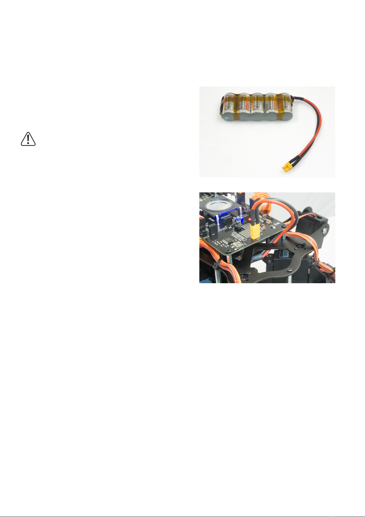
The "Hexapod Robobug" complete set comes with a type XT30 battery plug. This is
soldered to the battery selected by you. The cable length between battery and plug
mustnotexceed20cm!Fortheconnectioncable,werecommendusingahighlyex-
ible silicone cable with a cross-section of between 2 and 2.5 mm².
Pay attention to the polarity (plus/+ and minus/-), and that no short circuit is caused
by soldering.
In the event of a short-circuit, rechargeable batteries can emit a lot of current,
whichcanleadtoburnsandredamageaswellastodangerousinjuries.An
explosion of the battery is also possible!
The ready-made battery is provided with a battery shrink tube. This way the battery
looks clean at the end of the soldering work and indicates that there is no danger of a
short circuit.
In gure 7 you can see how the battery is plugged into the Robobug. The plug is
protected against reverse polarity and cannot therefore be plugged in the wrong way.
d) Installation of the software and rmware
Thesoftwarepackages,rmwareandtoolsrequiredforthe"HexapodRobobug"areavailableonlineasadownloadpackage.Thispackageisupdatedand
extended regularly. Please check occasionally whether a new version or useful extensions are available.
Open your web browser and navigate either via our shop website www.conrad.com to the product page of the "Hexapod Robobug" complete set, or visit our
download centre www.conrad.com/downlods. directly.
Here you can download the package "001664151-up-01-en-DOWNLOAD_BUNDLE_Vx_x" (x_x is the version of the package). The highest version number
correspondstothelatestversion!UnpackthedownloadedZIPleonyourharddisk.
Here is a short explanation of the included folders:
"Arduino" HereisatextlewiththedownloadlinkforthesoftwareArduino™IDEincluded.
Thisisneeded,forexample,toinstallthermwarewithoutanupdater.
"Datasheets" Data sheets and sketches
"Driver" Driver for the FTDI USB chip
"Librarydemos" ContainstheArduinolibrary,demo'sandtheLocomotionrmwareasaZIPle.WillbeinstalledintheArduinoIDE.
"Schematic" SchematicoftheHexapodRobotBoardasPDFle
"Terminal" Calibration software for setting the Hexapod
Figure 6
Figure 7
12
11. Transferring the Firmware
Ondelivery,normwareisinstalledontheHexapodRobotBoard.Thermwaremustrstbetransferredduringinitialcommissioning.Thisisdoneviathe
Arduino IDE.
Thefollowingdescriptionshowsyoutheprocedurefortransferringthermware.InthefollowingchaptersyouwilltransferdifferentprogrammestotheHexapod
Robot Board. The procedure is identical except for the selection of the respective program.
Whentransferring the rmware, theHexapodRobotBoardmustbeconnectedtothepowersupply (battery)! Makesurethatthebatteryisfully
chargedbeforetransferringthermwareorprogrammes.
a) Installing the driver
Connect the "PRG-M" port of the Hexapod Robot Board to a free USB port on your computer. Windows will now attempt to install a new driver. Typically,
Windows will automatically download and install the drivers from the Internet, since the driver for the "FTDI" USB bridge chip used is available in the Windows
driver download (the computer must be connected to the Internet for this to work).
If this method does not work, refer to the driver manually during installation. The driver is located in the unpacked download bundle, in the "Driver" directory.
After installing the driver, check in the device manager whether the driver for the Hexapod Robot Board has been installed and which COM port number has
been assigned. Then select them in the Arduino IDE.
You can also download the drivers directly from http://www.ftdichip.com .
b) Install Arduino IDE
You can download the latest version of the Arduino IDE from www.arduino.cc. The Arduino IDE is available as "installer version" and as "ZIP archive". Both
versions can be used.
With the installer version, you install the Arduino IDE as you would install any other programmes. With the ZIP version, you must unpack the ZIP archive to the
desiredlocationonyourcomputerafterthedownload.Thenstarttheprogrammebydouble-clickingonthele"arduino.exe".
ThecurrentrmwareversionwasdevelopedwithArduinoversion1.8.3.Ifthereareproblemswithnewerversions,downloadanolderversionofthe
Arduino IDE from www.arduino.ccandtransferthermwarewithit.
Also familiarize yourself with the board and its connectors. An overview of the board can be found in Chapter 19 Figure 79.
c) Setting up Arduino IDE
Start the Arduino IDE and follow the instructions in this manual.
Figure 8
13
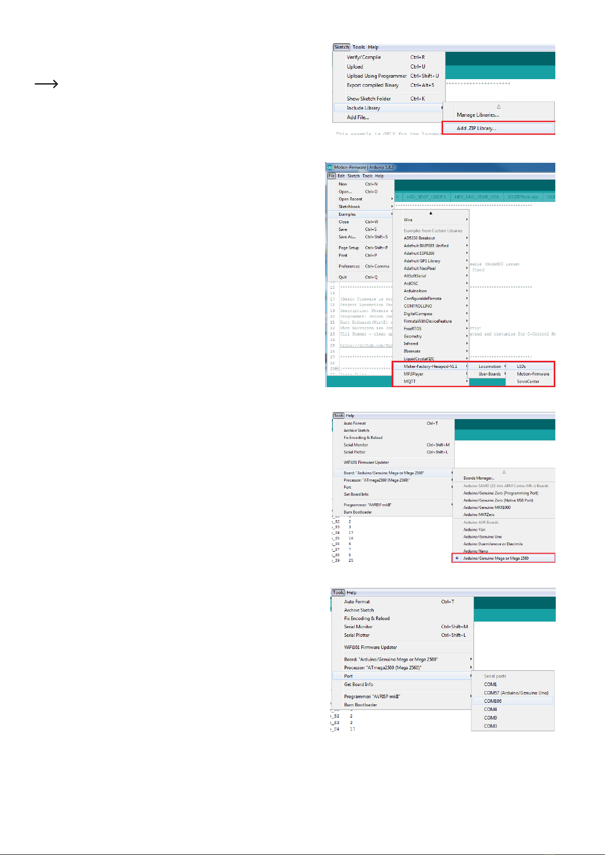
Now install the Hexapod library. It can be found in the download bundle under
"\Library-Demos\Maker-Factory-Hexapod-V1.1.zip". Select the menu item "Sketch\In-
clude Library\Add .ZIP Library..." in the Arduino IDE.
Ifyouupdatethelibrarylater,youhavetodeletetheoldlibraryrst,otherwise
the Arduino IDE will report an error!
Afteryouhaveinstalledthelibrary,youwillndtwofoldersnamed"Locomotion"and
"User-Boards" in the menu item "\File\Examples\Maker-Factory-Hexapod-Vx.x".
The folder "Locomotion" contains programmes for the Locomotion controller, which is
xedontheHexapodRobotBoardandisresponsiblefortheoperation.
The folder "User-Boards" contains programmes for the Arduino compatible user boards
like Arduino UNO and NodeMCU.
Select the microcontroller used under the menu item "Tools\Board\Arduino/Genuino
Mega".
The locomotion controller is compatible with the Arduino Mega 2560.
Select the COM port under "Tools\Port" that was assigned to the Hexapod Robot Board
during driver installation.
Figure 10
Figure 11
Figure 12
Figure 9

14
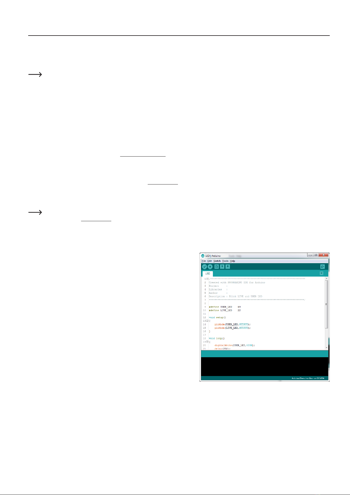
To test if everything works, transfer the sample programme "\User-Board\Locomotion\
LEDs". After successful transmission, the programme causes the blue "LIVE-LED" and
thered"USER-LED"toashalternately.
To transfer the programmes, the battery must be plugged into the Hexapod
Robot Board!
After selecting the "LEDs" programme (also called Sketch in Arduino) a new Arduino
IDE window opens with the "LEDs" Sketch.
With the "arrow to the right" symbol (see picture 14) in the menu you transfer the
programme to the Hexapod Robot Board. Alternatively, you can also use the shortcut
"CTRL+U".
This procedure applies to all programmes to be transferred (called sketches in the Arduino IDE) that are intended for the locomotion controller. For the user
board samples, you only change the applied user board in use and the "COM-Port".
Please read the respective initial comment in the source code of the examples before transferring. This contains important information about the
program!
If the transfer does not work, please check your settings for board and connection and also check if the board has been entered and installed correctly in the
device manager and if the power supply is connected.
HereyoucanndmoreinformationaboutinstallingtheArduinoIDE:http://arduino.cc/en/Guide/Windows
Leave the board plugged in for the next step, as you will need to move the leg servos to the centre position in this step.
Figure 13
Figure 14
15
12. Preparing the leg servos for installation
Before you install the leg servos, you must move them to the centre position. This means moving the servos to the mechanical middle position using the Hexa-
pod Robot Board and the "ServoCenter" program. This is the starting position for assembly.
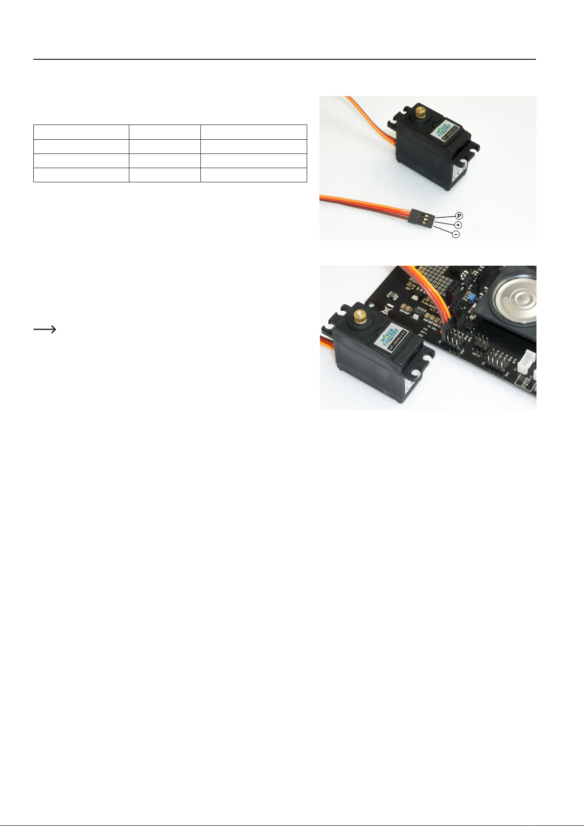
First unpack all 18 servos; then straighten all connecting cables.
Pin assignment:
Labelling in Figure 15 Function Imprints on PCB
P Control pulse SIG
+ Positive pole/+ BAT
- Negative pole/- GND
To set the leg servos, transfer the "ServoCenter" programme (located in the "Locomo-
tion" directory) to the Hexapod Robot Board. The programme automatically moves the
servos from "S0" to "S17" to the middle position.
Connectthe servos tothepin headersasshown in thegure (pay attentiontothe
polarity!). All servo connections (S0 to S17) of the robot board are controlled with a
pulsewidthof1500μs.
At this point you do not have to connect all 18 servos to the Hexapod Robot Board at
the same time. In practice, it has proven to be much easier and faster to use only one
connection (e.g., S0) and then move one servo after the other to the middle position.
The brown wire of the servo cable points to the edge of the board. The board is also
labelled SIG (pulse), BAT+ (+), GND (-).
The battery must be connected for this procedure!
Figure 15
Figure 16
16
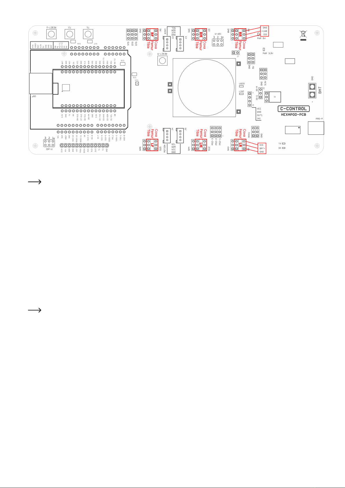
Figure 17
Figure 17 shows the pin headers to which the servos are connected.
The pin strips labelled SA0 to SA5 do not carry a control signal. This connection remains unassigned and can later be used for proper extensions such
as leg contact sensors.
The joint details are given anatomically in Latin and have the following meaning:
• Coxa = hip
• Femur = thigh
• Tiba = leg
The connections are also indicated in Figure 17 with the leg name as an abbreviation:
• RR = Right rear leg ("Right Rear")
• RM = Right Middle leg ("Right Middle")
• RF = Right front leg ("Right Front")
• LR = Left rear leg ("Left Rear")
• LM = Left middle leg ("Left Middle")
• LF = Left front leg ("Left Front")
Leave the programme on the Hexapod Robot Board until the robot is completely assembled. If you accidentally twist a servo mechanically during
assembly, you can plug it in again and align it.
If the servo is turned from the middle position during installation, this has a negative effect on the running characteristics. This can also damage the
servo and the mechanics.
Disconnect the robot board from the power supply in case you won't be using it for a long time to avoid accidental short circuits!
17
Functional description of a servo
Servos have electronics, a motor and a potentiometer.
The potentiometer picks up the mechanical position of the servo and forwards it to the
servo electronics.
The electronics in the servo compares the given position (nominal value, in our case
the pulse width given by the locomotion controller) with the pulse width of the servo
electronics (set via the potentiometer, actual value).
If there is a difference between the two pulse widths, the servo electronics regulates
the motor to the target position.
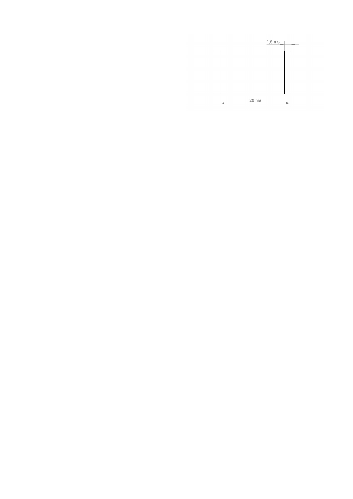
The graphic illustrates the pulse/pause ratio required to control a servo. In this case,
thepulsehasalengthof1.5ms=1500μs,whichcorrespondstothecentreposition
of the servo.
Aservoreceivesascontrolsignalapositivepulsewithapulsewidthbetween500μs
(0.5ms)and2500μs(2.5ms).Thetotalperioddurationofthecontrolsignalis20ms.
Whentheservoisinthemiddleposition,thepulsewidthis1500μs(1.5ms).
If the pulse width is less than 1.5 ms, the servo rotates in one direction. If the pulse width is greater than 1.5 ms, it rotates in the other direction. The angle of
rotation is proportional to the pulse width, i.e. the longer or shorter the pulse, the more or less the servo rotates in the corresponding direction.
Figure 18
18
13. Assembling the mechanical parts
The following illustrations illustrate the mechanical assembly.
Caution!
When tightening the plastic screws, make sure that they are not screwed too tightly into the plastic and that the plastic holders are not damaged!
Ifyouremoveascrewfromaplasticpartandthenscrewitinagain,rstturnthescrewanticlockwiseuntilyounoticethatthescrew"engages".Atthis
point the screw is "engaged" in the existing thread. The screw can then be easily screwed into the thread that has already been created during the
rstscrewingin.Iftheself-tappingplasticscrewisscrewedinwithoutusingthismethod,anewthreadmayoccur.Thisweakensthematerialandthe
tensile strength as well as the hold are no longer guaranteed.
a) Mounting servos
Mount the servos as shown in the following illustrations. You will need 3 pairs of left and 3 pairs of right legs.
Most aluminium parts have a slightly rounded side due to the manufacturing process (punching process). You can use the parts in both directions during as-
sembly. The nicer side should point forward in the direction of travel. The rounded side of the top and bottom plates should point in the same direction (top or
bottom).
Required tool: 1x PH2 Cross Screwdriver
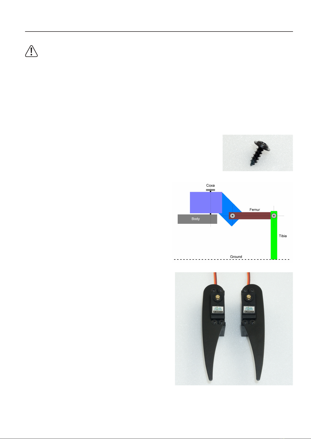
The screws are packed in plastic bags in the kit. Figure 19 shows the type of screws used for servo mounting.
A total of 6x legs must be assembled (3 left and 3 right).
Figure 20 shows a leg of the Robobug. The leg elements are called "Coxa", "Femur"
and "Tibia".
Place the servo in the plastic U-angle and the aluminium leg thereon (pay attention to
the left and right leg and the round edge).
The servo cable is pushed through the oval opening in the U-angle.
Screw the leg together with four plastic screws.
When screwing the parts together, align them so that they are centred in the U-angle,
the aluminium legs lie against the servo and ensure that nothing is strained or warped.
If necessary, loosen the screws a little to relax the mechanics and then carefully tighten
the screws crosswise.
Figure 19
Figure 20
Figure 21

19
The Coxa servo and femur servo holder must be mounted 6 times (3 left and 3 right).
First insert a servo into the holder and screw it on. Only then is the second servo plugged in and screwed in.
The servo cable of the Coxa servo is inserted through the round opening at the top and the servo cable for the femur servo is inserted through the large oval
opening as with the U-angle mounting.
Screw the servos together with four plastic screws.
When screwing the servos together, align them so that they are centred in the plastic holder and are not tensed. If necessary, loosen the screws a little to
release the mechanical tension and then carefully tighten the screws crosswise.
Figure 22
Figure 23
20
b) Mounting of bearings
Required tool: 10 mm hexagon socket (from a socket wrench set) or comparable tool as a tool for mounting the bearings
Push the bearings into the aluminium parts as shown in the following illustrations. Here a hexagon socket wrench or a comparable tool can be helpful. Do not
use rough force, this can damage the base plate and the ball bearings! Avoid tilting, with some sensing the position can be pressed in without great resistance.
Makesurethattheedgeofthebearingisushwiththealuminiumpart.
If a bearing cannot be pressed in, it may be caused by a protruding burr or too much paint. You can easily rework the bore with a knife (e.g., cutter
knifeforwallpaperoroors)orwithale.Iftheborehasbecometoolarge,thebearingcanbegluedtotheangeofthebearingwithasmalldropof
glue (e.g., Uhu®Endfest or comparable).
Thebearingsmaycomelooseduringnalassemblyduetounevenpressingofthecylindricalpinsintotheplasticholders.Thisis,however,nottoo
bad, as the pins can easily be pushed back into the intended hole.
Stickingshouldbealastresort.Thebearingsclampsufcientlystronglyintheholesfortheoperationoftherobotevenwithoutglue.
Figure 24
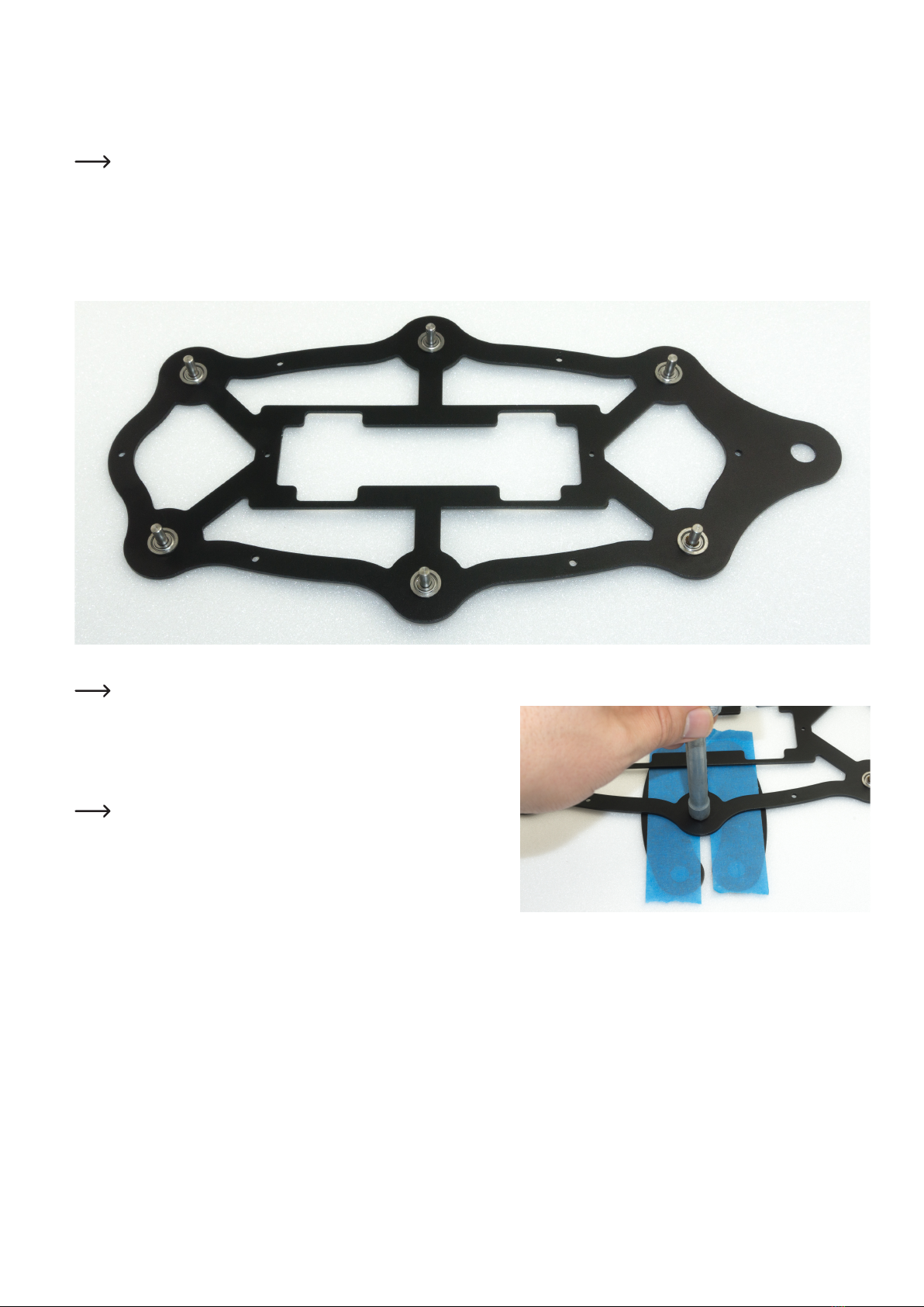
Figure 24 shows the bottom plate from above!
Figure 25 shows how you can press the bearings into the base plate using the femur
aluminium parts as a support.
The hexagon wrench must press against the edge of the bearing. Masking the alu-
minium parts with painter tape protects them from scratching. Other parts that can be
found in the hobby workshop can also be used as underlay.
Do not use adhesive tape that cannot be removed without leaving a residue.
Figure 25
This manual suits for next models
1
Table of contents


