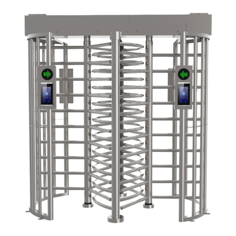
Makim T2500D SINGLE 3 User manual

2019
FULLHEIGHT TURNSTILE
USER MANUAL
T2500D SINGLE 3 ARMED
T2500D SINGLE 4 ARMED
T2500D DOUBLE 3 ARMED
T2500D DOUBLE 4 ARMED
T2500K SINGLE 3 ARMED
T2500K SINGLE 4 ARMED
T2500K DOUBLE 3 ARMED
T2500K DOUBLE 4 ARMED

Contents
Attention
Technical Specificitaion
Physical Specifications
Installation and Mounting
Connections
Maintenance Instruction
Documents
3
3
4
6
7
8
9

Read the all manual, before operating the turnstile and keep
the manual for future usage .
Do not place the devicon moving floor.
Take measures to prevent people or any substance from
contacting the appliance with the power cable.
Protect your turnstiles with strong grounding.
In order to prevent physical injury, take measures to
prevent crossing through the turnstile or outside the
passageway.
Do not spray water directly on the turnstile.
Contact your authorized service center for turnstile
maintenance and repair.
Products must be in their original packaging when transported.
Pay attention to the instructions on the packaging for loading,
transport and stacking.
Bi-directional
Manual
Optional AISI 304 stainless steel or painted body
Mono-block mechanism. ST37 steel material with various covers
Warning indicator for each light in both directions
(green arrow-red cross)
220V50Hz /30W power consumption
24VDC +-%20 operation voltage
0'C +70'C operation temprature
IP42 protection
Attention
Technical Specifications
3

Physical Specification
Dimensions are given in 'mm'.
4
T2500D
SINGLE
3 ARMED
T2500D
DOUBLE
3 ARMED
T2500D
DOUBLE
4 ARMED
T2500D
SINGLE
4 ARMED

Dimensions are given in 'mm'.
5
T2500K
SINGLE
3 ARMED
T2500K
SINGLE
4 ARMED
T2500K
DOUBLE
3 ARMED
T2500K
DOUBLE
4 ARMED

Installation-Mounting
Mounting kit supplied as standard along with the turnstiles
consists of studs and washers Follow the procedure below for
installation:
Mark the hole places on the ground in which the turnstile will
be mounted.
Drill 8 cm deeped marked mounting holes by 12mm drill top
as using drill and hilt.
Fix the steel anchors to the drilled holes. If the ground is not
strong, fix the steel anchors using chemical soil mixture
(recommended one is Hilti HIT HY 150). Wait 20 minutes for
hardening of chemical soil mixture.
6
Concrete thickness should be at least '400 mm'.
Concrete edge dimensions should be at least '100 mm' longer than the turnstile dimension.

Card Reader Connection
J5
SER+
SER-
When the button and remote control are connected to this port, the
turnstile switches to free mode.
J5
GIR+
GIR-
This port must be operated with pushbutton or relay output. Max. 1
second is recommended. When a signal is received from J5, the
turnstile opens in the direction of entry. (If the set mode input
direction is set to controlled pass).
J5
CIK+
CIK-
This port must be operated with pushbutton or relay output. Max. 1
second is recommended. When a signal is received from J5, the
turnstile opens in the exit direction. (If the set mode output direction
is set to controlled pass).
Mode Settings
SW-3
(MODE)
When the Mode button is touched, the LED 5 lights up. The card is in
program mode. Press the button of the desired direction to make the
program.
SW-1
(GİRİŞ)
After pressing the MODE button, the card will switch to 'LOCKED',
'CONTROLLED', 'FREE' modes each time this switch is touched. After
selecting the desired mode, press MODE SW-3 again. LED 5 is off. The
tourniquet is then programmed to the desired mode.
SW-2
(ÇIKIŞ)
Each time the switch is pressed, the card will switch to 'LOCKED',
'CONTROLLED', and 'FREE' modes, respectively. After selecting the desired
mode, press MODE SW-3 again. LED 5 is off. The tourniquet is then
programmed to the desired mode.
The preferred power source for the turnstile is 25W, 24V, 1.1A. A power
supply below these values should not be used.
L N Port: 220AC V is applied. A grounding line is drawn from the ground
symbol to the turnstile body.
-V +V Port: Connect to V+(+) to V- (-) towards J1 socket of BM32 control
board.
Fullheight turnstiles operate with 220VAC voltage. Power cable which will be used in turnstiles must be min.
3 x 1.5 TTR. Power cable and ground connections points must be screwed in tightly.
BM32 Control Board
Power Supply
Connections
7

Turnstile Body
Dust is removed with a damp cloth. Chemicals adhering to the
surface are cleaned with Würth brand stainless cleaning spray. (1-
4 weeks)
Connectors
The reason of the jerky operation of the turnstile is that the wrong
installation or the connection elements are weakened in time. The
fasteners must be checked and the damaged parts replaced. (6
Months)
Selenoid
Solenoid is observed to prevent any problems in the locking
system. Replacement of parts in case of problems in operation or
locking. (12 Months)
Hydraulic
Damper
The turnstile arm is rotated one turn to control the damper. If the
arm stops decelerating when completing the lap and there is no
impact, the damper setting is normal and operational. If the
rotation cannot be completed or multiplied, the damper setting is
checked first, if not, it is replaced with a new one. In addition, the
damper needs to be adjusted due to seasonal temperature
differences. The screw on the back of the damper is placed in the
1.5-2 position in the summer, and in the 2-3 position in the winter,
allowing the turnstile arm to stop softly and without impact. If the
damper adjustment is not done well, the relevant mechanism parts
(lock paws, bobbins, etc.) will wear out more quickly. (12 months)
Connection
Cables
The solenoid and micro switches on the mechanism are visually
controlled. The tightness and connections of the Megaradar 10-
position terminal screws are checked. (12 months)
Central Control
Equipments and
Rotation Parts
The mechanism is rotated one turn to see if it is working properly, rotating
parts (Central Control Element Tubes) and working surfaces. The
problematic parts are checked and replaced if necessary. If there is no
problem in operation, the tubes and working surfaces are lubricated with
WD40 spray and the maintenance is completed. (These parts are shipped
from production by lubricating with WD40 spray.) (12 months)
Electronic
Equipment and
Cabling
The plugs (connectors) of the transition cards between the cards
and the cables from the cards to the turnstile assembly are
checked. The turnstile works by observing the turnstile. If there is
no problem in the turnstile operation, the system is operational.
If a problem is observed in the study, problem cards are identified
and replaced with a new one. (12 months) Note: It is
recommended to use Würth brand oxide cleaner for cleaning.
System Operating
Control and
Maintenance
Validator and card reader system operation, operation, detailed
control and maintenance information can be found in the
validator and card reader document.
8
The maintenance tips and times given in this part are general informations. It is
suggested to the user to decide maintenance instructios himself depending on
environmental and usage conditions. Turnstile must have maintenance by
authorized service periodically. In case it is not possible to connect with an
authorized dealer, get into contact with manufacturer company and obtain
information on periodical maintenance. The following are the control periods of
the spare parts and the operations to be performed:
Maintenance Instruction

Documents
9
This manual suits for next models
7
Table of contents
Other Makim Turnstile manuals
