Makita DJR186 Manual

April 2016
TECHNICAL INFORMATION
OFFICIAL USE
for ASC & Sales Shop
Cordless Recipro Saw
Model No. DJR186
Description
CONCEPT AND MAIN APPLICATIONS
Model DJR186 is a Cordless recipro saw powered by 18V Li-ion battery and
has been developed for higher cutting efficiency and
more durability than the current models DJR181/ DJR182 by adopting
Vertical crank mechanism and reviewing specifications.
Its main features are:
• Ergonomically designed handle
• High durability thanks to more rigid shoe and durable mechanism
to support slider
• Toolless blade change
• Enhanced performance of cutting speed and stroke length
• Vertical crank mechanism minimizes blade deflection and reduces
vibration to machine.
• Two-finger switch trigger
Note: BL1815 is not compatible.
Specification
Model
Specification DJR186
Battery
Voltage: V 18
Capacity: Ah 1.5, 2.0, 3.0, 4.0, 5.0, 6.0
Energy capacity: Wh 27, 36, 54, 72, 90, 108
Cell Li-ion
Charging time (approx): min 15, 24, 22, 36, 45, 55 with DC18RC
Max output (W) 530
Strokes per minutes: min-1= spm (strokes per minute) 0 - 2,800
Length of stroke: mm (") 32 (1-1/4)
Capacity: mm (") Wood*2255 (10)
Pipe: Ø 130 (5-1/8)
Blade clamp type Toolless
Electric brake Yes
Variable speed control by trigger Yes
Weight according to
EPTA-Procedure 01/ver.2.1: kg (lbs) 3.5 (7.6)*3or 3.8 (8.3)*1
*2 When 300mm (11-3/4") blade is used.
*3 With battery BL1815N, BL1820(B)
Dimensions: mm ( " )
Length (L) 486 (19-1/8)
Width (W) 81 (3-3/16)
Height (H) 223 (8-3/4)*1
*1 With battery BL1830(B), BL1840(B),
BL1850(B), BL1860B
Recipro saw blade 152mm (6") for wood and metal
Recipro saw blade 200mm (7-7/8") for metal
Battery*4
Charger*4
Battery cover*5
Plastic carrying case*4
*4 Battery and Charger and Plastic carrying case are not supplied with “Z” model.
*5 Supplied with the same quantity of extra Battery.
Note: The standard equipment may vary by country or model variation.
Recipro saw blades
Fast charger DC18RC
Charger DC18SD
Charger DC24SC
Automotive charger DC18SE
Two port multi fast charger DC18RD
Four port multi charger DC18SF
Battery BL1815N
BL1820(B),
BL1830(B), BL1840(B),
BL1850(B), BL1860B
Standard equipment
Optional accessories
W
L
H
1 / 22

1INDEX
1INDEX.......................................................................................................................................................................................... 2
2CAUTION .................................................................................................................................................................................... 3
3NECESSARY REPAIRING TOOLS ........................................................................................................................................... 3
4LUBRICANT AND ADHESIVE APPLICATION ...................................................................................................................... 4
5REPAIR ........................................................................................................................................................................................ 6
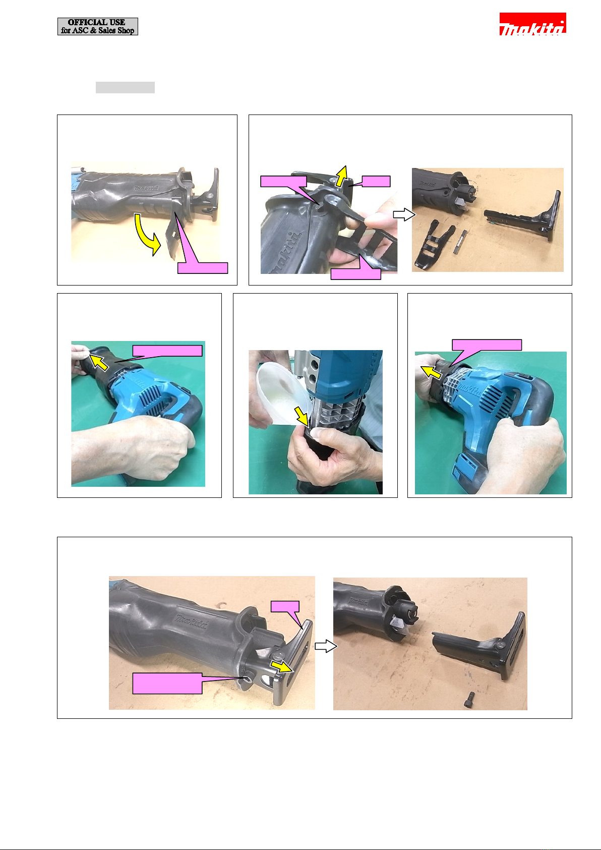
5-1 Insulation cover.................................................................................................................................................................... 6
5-1-1 Disassembling ............................................................................................................................................................. 6
5-1-1-1 For DJR187, DJR360.............................................................................................................................................. 6
5-1-1-2 For DJR186............................................................................................................................................................. 6
5-1-2 Assembling.................................................................................................................................................................. 7
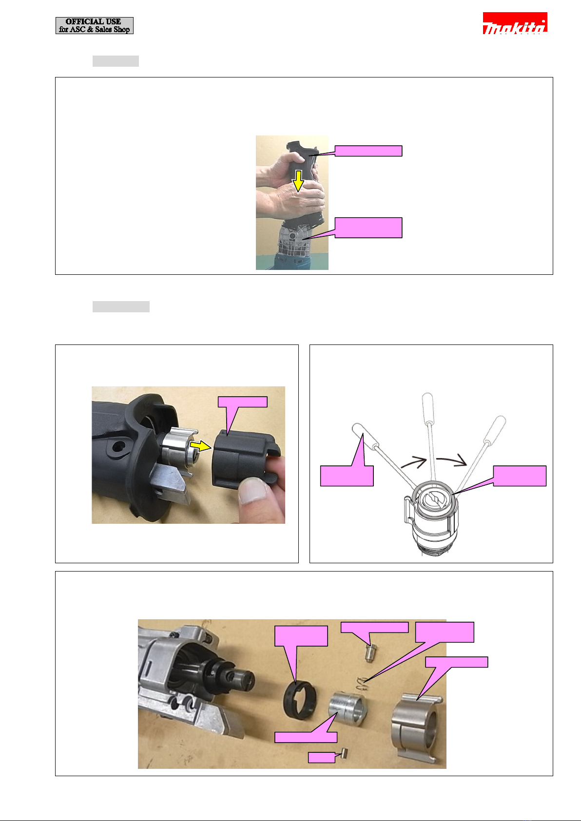
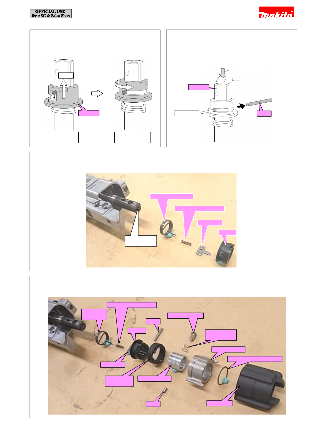
5-2 Slider assembly .................................................................................................................................................................... 7
5-2-1 Disassembling ............................................................................................................................................................. 7
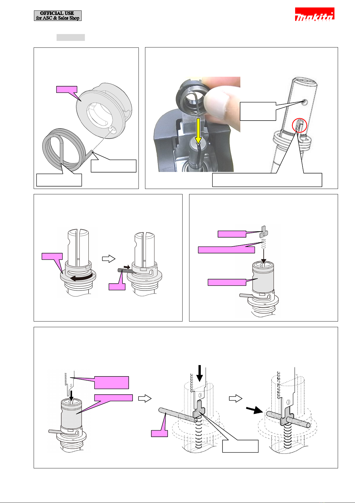
5-2-2 Assembling.................................................................................................................................................................. 9
5-3 Rotor ass'y (Armature ass'y)............................................................................................................................................... 12
5-3-1 Disassembling ........................................................................................................................................................... 12
5-3-1-1 For DJR187, DJR360............................................................................................................................................ 12
5-3-1-2 For DJR186........................................................................................................................................................... 14
5-3-2 Assembling................................................................................................................................................................ 15
5-3-2-1 For DJR187, DJR360............................................................................................................................................ 15
5-3-2-2 For DJR186........................................................................................................................................................... 16
5-4 Gear complete .................................................................................................................................................................... 17
5-4-1 Disassembling ........................................................................................................................................................... 17
5-4-1-1 For DJR187, DJR360............................................................................................................................................ 17
5-4-1-2 For DJR186........................................................................................................................................................... 18
5-4-2 Assembling................................................................................................................................................................ 19
5-5 Slider section...................................................................................................................................................................... 19
5-5-1 Disassembling ........................................................................................................................................................... 19
5-5-2 Assembling................................................................................................................................................................ 19
6Circuit diagram ........................................................................................................................................................................... 20
7Wiring diagram ........................................................................................................................................................................... 21
2 / 22

2CAUTION
Repair the machine in accordance with “Instruction manual” or “Safety instructions”.
Follow the instructions described below in advance before repairing:
· Wear gloves.
· Remove the recipro saw blade from the unit.
· In order to avoid wrong reassembly, draw or write down where and how the parts are assembled, and what are the parts.
It is also recommended to have boxes ready to keep disassembled parts by group.
· Handle the disassembled parts carefully. Clean and wash them properly.
· If some bolts and screws are too tight, use an impact driver.
· Tighten the bolts and the screws to the specified torque.
3NECESSARY REPAIRING TOOLS
Code No.
Description
Use for
1R269
Bearing extractor
removing Ball bearings
1R291
Retaining ring S and R pliers
removing Retaining ring S-12
3 / 22

4LUBRICANT AND ADHESIVE APPLICATION
Apply the following lubricants and adhesives.
Item No.
Description
Portion to lubricate
Lubricant
Amount
16
Slider
Outer circumference
Makita grease
FANo.2
a little
17
Roller
Inner surface
-
Gear shaft
Outer circumference
27 Flat washer 4
Side surface that contacts Needle bearing
1012 of Gear complete
28
Gear complete
Gear portion
14g
29
Flat washer 54
Both side surfaces (front and back)
a little
32 Rod guide L
(a) Side surfaces that contact Roller
(b) Bottom surface that contacts Roller
1g
39
Gear housing L
Around Slider
5g
Fig. 4-1
Gear complete
Flat washer 54
(a) Rod guide L
Gear shaft
Roller
(b) Rod guide L
Gear housing L
Gear housing L
Slider
Flat washer 4
4 / 22

Item No.
Description
Portion to lubricate
Lubricant
Amount
4
Shoulder pin 5
Head point
Makita grease
FANo.2
a little
5
Compression spring 6
Outer circumference
8
Pin 3
Outer circumference
15
Slider guide complete
Inner circumference (both sides)
18
Pin 6
Outer circumference
19
Roller
Inner circumference
22 Rod guide R
(a) Side surfaces that contact Roller
(b) Bottom surface
1g
23
Gear housing R
Around Slider
5g
69
Felt 16x16
Whole surface
Lubricant VG100
a little
14
Rubber ring
Between Rubber ring and Seal ring ThreeBond 1215
30
Seal ring
Gear housing R
(b) Rod guide R
(a) Rod guide R
Roller
Pin 6
Slider guide complete
Pin 3
Shoulder pin 5
Compression
spring 6
Felt 16x16
Seal ring
Rubber ring
Fig. 4-2
5 / 22

5REPAIR
5-1 Insulation cover
5-1-1 Disassembling
5-1-1-1 For DJR187, DJR360
5-1-1-2 For DJR186
[2] Pull out Insulation cover. (Fig. 5-1-1-1-3, Fig. 5-1-1-1-4, Fig. 5-1-1-1-5)
Fig. 5-1-1-1-1
[1] Pull Lock lever.
Fig. 5-1-1-1-2
[2] Pull out Shoe.
[3] Remove Lock lever, and remove Lock pin.
Lock lever
Shoe
Lock pin
Lock lever
Fig. 5-1-1-1-3
[4] Pull and slide Insulation cover
forward.
Fig. 5-1-1-1-5
[6] Pull out Insulation cover.
Insulation cover
Fig. 5-1-1-1-4
[5] Pour soapy water between Gear
housing assembly and Insulation
cover.
Insulation cover
Fig. 5-1-1-2-1
[1] Loosen M6x14 Hex socket head bolt, and remove Shoe.
Shoe
M6x14 Hex
socket head bolt
6 / 22

5-1-2 Assembling
5-2 Slider assembly
5-2-1 Disassembling
[1] Pull out Shoe. (Refer to 5-1 Insulation cover.)
Fig. 5-1-2-1
Apply soapy water onto the inner circumference of Insulation cover, and mount Insulation cover to Gear housing assembly by
thrusting it.
Note: Apply Loctite 272 on M6x14 Hex socket head bolt when you use it again. (Fig. 5-1-1-2-1)
Insulation cover
Gear housing
assembly
Fig. 5-2-1-1
[2] Remove Protector.
Fig. 5-2-1-2
[3] Insert a slotted screwdriver from the end of Retaining
ring 18, then pry it off.
Protector
Slotted
screwdriver
Retaining
ring 18
Fig. 5-2-1-3
[4] Remove Driving sleeve guide, Guide sleeve, Pin 3, Shoulder pin 5, Compression spring 6 and Driving sleeve.
Note: Be sure not to lose Shoulder pin 5 and Compression spring 6.
Driving
sleeve guide
Shoulder pin 5
Compression
spring 6
Driving sleeve
Guide sleeve
Pin 3
7 / 22

Fig. 5-2-1-4
[5] Twist Sleeve while pulling it up toward the blade install
side to set it in release position.
Fig. 5-2-1-5
[6] While holding the top of Slider by finger, push out Pin 3
with a thin bar.
Note: Without holding Slider, Push plate will pop out from
the slit of Slider.
Sleeve
Pull
Sleeve in Lock
position
Sleeve in release
position
Pin 3
Slider
Pull out
Fig. 5-2-1-6
[7] Remove Sleeve, Push plate, Compression spring 2 and Torsion spring 17. (Compression spring 2 is in the groove on Slider.)
Groove on
Slider
Torsion spring 17
Compression spring 2
Push plate
Sleeve
Fig. 5-2-1-7
[8] The components of Slider assembly are as follows:
Compression spring 2
Torsion
spring 17
Pin 3
Sleeve
Shoulder pin 5
Compression
spring 6
Driving sleeve
Retaining ring (EXT) 18
Protector
Pin 3
Guide sleeve
Driving
sleeve guide
Push plate
8 / 22

5-2-2 Assembling
Fig. 5-2-2-1
[1] Assemble Torsion spring 17 to
Sleeve by inserting its short tail into
the hole of Sleeve.
Fig. 5-2-2-2
[2] Set Sleeve by passing the long tail of Torsion spring 17 through the slit of
Slider.
Fig. 5-2-2-4
[4] Mount Guide sleeve temporarily, then Put Compression
spring 2 and Push plate into the slit of Slider.
Hole where
Pin 3 is
installed
Note: Face the short tail of Torsion spring 17
to the hole where Pin 3 is installed.
Sleeve
Short tail of
Torsion spring 17
Long tail of
Torsion spring 17
Fig. 5-2-2-3
[3] Turn Sleeve clockwise and insert Pin 3 into the hole
temporarily as shown below.
Sleeve
Pin 3
Compression spring 2
Guide sleeve
Push plate
Fig. 5-2-2-5
[5] While pushing Push plate straight into Slider with Recipro sawblade, insert pin 3 through the hole of Push plate as shown
below. Then remove Guide sleeve.
Note: Guide sleeve is used as a jig. Do not assemble it to Slider in this step.
Recipro saw
blade
Guide sleeve
Pin 3
Hole of Push
plate
9 / 22

Fig. 5-2-2-6
[6] Remove Guide sleeve.
Fig. 5-2-2-7
[7] Set Driving sleeve to Sleeve while fitting its two projections to
the two concaves of Sleeve.
Guide sleeve
Fig. 5-2-2-8
[8] While push Driving sleeve into Gear housing, turn the sleeve clockwise to lock Pin 3 in place. Then, remove Driving sleeve.
Viewed from the bottom
Driving sleeve
Projections
Concaves of
Sleeve
Pin 3
Sleeve
Driving sleeve
10 / 22

Fig. 5-2-2-10
[10] Mount Guide sleeve.
Fig. 5-2-2-9
[9] Mount Driving sleeve guide while aligning its notches
to the concaves of Sleeve.
Concaves of Sleeve
Driving
sleeve guide
Guide sleeve
Fig. 5-2-2-12
[12] Mount Pin 3.
Fig. 5-2-2-11
[11] Mount Compression spring 6 and Shoulder pin 5 into the
holes of Guide sleeve/ Slider.
Shoulder pin 5
Compression
spring 6
Pin 3
Fig. 5-2-2-13
[13] Put Driving sleeve over Guide sleeve and secure them with Retaining ring (EXT) 18 using 1R291.
Then, install Protector to Driving sleeve.
Note: Fit its projections in the concaves of Sleeve and Driving sleeve guide.
Driving sleeve
Guide sleeve
Projection
Concave of Sleeve and
Driving sleeve guide
Retaining ring
(EXT) 18
Retaining ring
(EXT) 18
Protector
Driving
sleeve
11 / 22

5-3 Rotor ass'y (Armature ass'y)
5-3-1 Disassembling
5-3-1-1 For DJR187, DJR360
[1] Remove Insulation cover. (Refer to 5-1 Insulation cover.)
Fig. 5-3-1-1-1
[2] Loosen two M5x10 Pan head screws, and remove Hook assembly.
M5x10 Pan head
screw (2 pcs.)
Hook assembly
Fig. 5-3-1-1-2
[2] Loosen six 4x18 Tapping screws, and remove Handle set.
Handle set
4x18 Tapping screw
(6 pcs.)
(7 pcs. for DJR360)
Fig. 5-3-1-1-4
[5] Be careful thatM5 Square nut does not fall.
Fig. 5-3-1-1-3
[4] Disconnect the connector of LED circuit.
LED
circuit
M5 Square
nut
12 / 22

Fig. 5-3-1-1-5
[6] Loosen four M5x25 Pan head screws, and remove Motor housing section.
M5x25 Pan head
screw (4 pcs.)
Motor housing section
Fig. 5-3-1-1-6
[7] Loosen twoM4x16 Pan head screws, and remove Rotor ass'y.
Note: If it is hard to remove Rotor ass'y, warm Gear housing L assembly with a heat gun.
Rotor ass'y
M4x16 Pan head
screw (2 pcs.)
Fig. 5-3-1-1-8
[9] Remove Ball bearing 6201DDWwith 1R269, and remove Flat
washer 12 and Bearing retainer 66.
Fig. 5-3-1-1-7
[8] Remove Retaining ring S-12 with 1R291.
Retaining ring
S-12
1R291
Ball bearing 6201DDW
1R269
Flat washer 12
Retaining
ring S-12
Ball bearing
6201DDW
Bearing
retainer 66
13 / 22

5-3-1-2 For DJR186
[1] Remove Insulation cover. (Refer to 5-1 Insulation cover.)
[2] Remove two Brush holders.
Fig. 5-3-1-1-9
[10] Remove Ball bearing 607ZZ with 1R269.
Ball bearing
607ZZ
1R269
Fig. 5-3-1-2-1
[3] Loosen four M5x25 Pan head screws, and remove Motor housing section.
M5x25 Pan head
screw (4 pcs.)
Motor housing section
Fig. 5-3-1-2-2
[4] Loosen two M4x16 Pan head screws, and remove Armature ass'y.
Note: If it is hard to remove Armature ass'y, warm Gear housing L assembly with a heat gun.
Armature ass'y is assembled at the factory under severe quality control, so do not disassemble it.
M4x16 Pan head
screw (2 pcs.)
Armature ass'y
14 / 22

5-3-2 Assembling
[1] Assemble by reversing the disassembly procedure. Be careful to check the points mentioned in Fig. 5-3-2-1-1, Fig. 5-3-2-1-2.
Note: When assembling Rotor ass'y to Motor housing, be careful not to pinch your fingers between Rotor ass'y and Baffle plate.
Caution for Handling of Rotor ass'y (Armature ass'y)
When handling or storing multiple Rotors, be sure to keep a proper distance between Rotors as shown in Fig. 5-3-2-1-1.
Because Rotor has strong magnetic force, failure to follow this instruction could result in:
· Finger injury caused by pinching between Rotors pulling each other
· Magnetic loss of Rotors or damage on the magnet portion of Rotor (Fig. 5-3-2-1-2)
5-3-2-1 For DJR187, DJR360
Fig. 5-3-2-1-2
Fig. 5-3-2-1-1
Fig. 5-3-2-1-4
[3] Check that M5 Square nut is inserted into Motor
housing.
Fig. 5-3-2-1-3
[2] Set the U-shaped legs of Bearing retainer 66 into the
groove of Gear housing L assembly to assemble
Armature ass'y.
Note: If it is hard to assemble Armature ass'y, warm Gear
housing L assembly with a heat gun.
U-shaped legs of
Bearing retainer 66
Groove of Gear
housing L assembly
M5 Square nut
M5 Square nut
15 / 22

5-3-2-2 For DJR186
Fig. 5-3-2-2-2
[3] Align the notch of Yoke unit with the rib of Motor
housing, then set Yoke unit in place.
Fig. 5-3-2-2-1
[2] Set the U-shaped legs of Bearing retainer 66 into the
groove of Gear housing L assembly to assemble
Armature ass'y.
Note: If it is hard to assemble Armature ass'y, warm Gear
housing L assembly with a heat gun.
U-shaped legs of
Bearing retainer 66
Groove of Gear
housing L assembly
Rib of Motor
housing
Notch of Yoke unit
Yoke unit
16 / 22

5-4 Gear complete
5-4-1 Disassembling
5-4-1-1 For DJR187, DJR360
[1] Remove Insulation cover. (Refer to 5-1 Insulation cover.)
[2] Remove Rotor ass'y (Armature ass'y). (Refer to 5-3 Rotor ass'y (Armature ass'y).)
Fig. 5-4-1-1-1
[3] Loosen twoM4x35 Hex socket head bolts, and remove Shoe guide plate.
M4x35 Hex socket
head bolt (2 pcs.)
Shoe guide plate
Fig. 5-4-1-1-2
[4] Loosen fiveM4x16 Pan head screws, and remove Gear housing R complete.
Note:
· Roller may be attached on Gear housing R complete.
· If LED circuit is removed, be sure to assemble it again.
Gear housing R
complete
M4x16 Pan head
screw (5 pcs.)
Roller
Fig. 5-4-1-1-4
[6] Remove the assembled part of Gear complete and
Slider.
Fig. 5-4-1-1-3
[5] LoosenM4x8 Hex socket head bolt, and remove Flat
washer 4.
M4x8 Hex
socket head bolt
Flat washer 4
Gear complete
Slider
17 / 22

5-4-1-2 For DJR186
[1] Remove Insulation cover. (Refer to 5-1 Insulation cover.)
[2] Remove Rotor ass'y (Armature ass'y). (Refer to 5-3 Rotor ass'y (Armature ass'y).)
[4] Loosen M4x8 Hex socket head bolt, and remove Flat washer 4. (Fig. 5-4-1-1-3)
[5] Remove the assembled part of Gear complete and Slider. (Fig. 5-4-1-1-4)
[6] Remove Gear complete (Spiral bevel gear 44) from Slider. (Fig. 5-4-1-1-5)
Fig. 5-4-1-1-5
[7] Remove Gear complete (Spiral bevel gear 47) from Slider.
Fig. 5-4-1-2-1
[3] Loosen sevenM4x16 Pan head screws, and remove Gear housing R complete.
Note: Roller may be attached on Gear housing R complete.
Roller
Slider
Pin 6
Roller
Gear complete (Spiral bevel gear 47)
Roller
M4x16 Pan head
screw (7 pcs.)
Gear housing R
complete
18 / 22

5-4-2 Assembling
[3] If LED circuit is removed, be sure to assemble it again.
5-5 Slider section
5-5-1 Disassembling
[1] Remove Insulation cover. (Refer to 5-1 Insulation cover.)
[2] Remove Slider assembly. (Refer to 5-2 Slider assembly.)
[3] Remove Rotor ass'y (Armature ass'y). (Refer to 5-3 Rotor ass'y (Armature ass'y).)
[4] Remove Gear complete. (Refer to 5-4 Gear complete.)
5-5-2 Assembling
Fig. 5-4-2-2
[2] Assemble Felt 16x16 between Slider guide complete
and Gear housing L assembly, and push it in the
direction of the arrow.
Fig. 5-4-2-1
[1] Insert the longer part of Shoulder pin 6-8 into Gear
housing L assembly.
Note: For DJR186
Longer part
Shoulder pin 6-8
Gear housing L
assembly
Gear housing L
assembly
Felt 16x16
Slider guide
complete
Fig. 5-5-1-1
[5] Remove Slider guide complete from Slider.
Slider
Slider guide
complete
Fig. 5-5-2-1
Assemble Slider guide complete to Slider as shown below.
Slider
Slider guide
complete
19 / 22

6Circuit diagram
Fig. 6-1
M2
M1
+
AS
-
Black/AWG14
Line filter (if used)
Brush holder
(Right side viewed from the
back of the machine)
Red/ AW G 1 4
Brush holder
(Left side viewed from the
back of the machine)
Heat sink
FET
Insulated
connector
Insulated
connector
Switch
Red/AWG14
Yellow/AWG22
Flag receptacle with
lock (#250, t=0.8mm)
Straight receptacle
with lock (#187, t=0.8)
Terminal
Straight receptacle
with lock (#250, t=0.8)
Black/AWG14
Polyolefin tube
(inner diameter:
ø4.0mm)
Yellow/AWG20
Red/AWG14
Black/AWG14
20 / 22
Other manuals for DJR186
8
Other Makita Cordless Saw manuals

Makita
Makita JV183DZ User manual

Makita
Makita JV143D User manual

Makita
Makita 4334D User manual

Makita
Makita JV002G User manual

Makita
Makita DJR186 User manual

Makita
Makita VJ04 User manual

Makita
Makita XSH10 User manual

Makita
Makita BJR181 User manual

Makita
Makita DJV182 User manual

Makita
Makita CXTJV102DZ User manual

Makita
Makita XRJ01 User manual

Makita
Makita BJR181ZK User manual

Makita
Makita XVJ05 User manual

Makita
Makita JR3000V User manual

Makita
Makita DHS680 User manual

Makita
Makita BSS501Z User manual

Makita
Makita JV102DZ User manual

Makita
Makita DSS610 User manual

Makita
Makita HS009G User manual

Makita
Makita RS001GM101 User manual