P 2 / 17
Repair
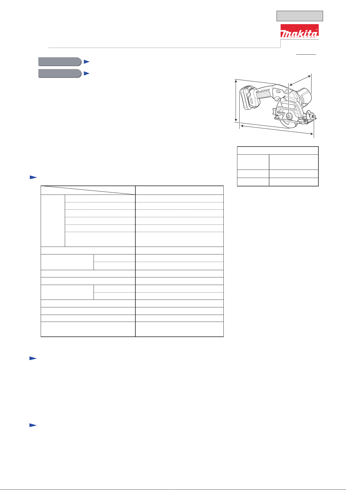
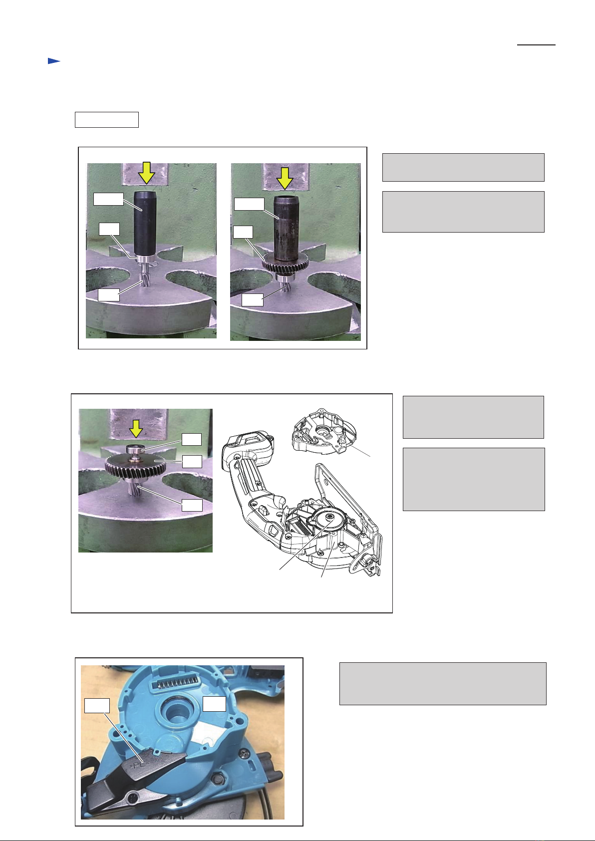
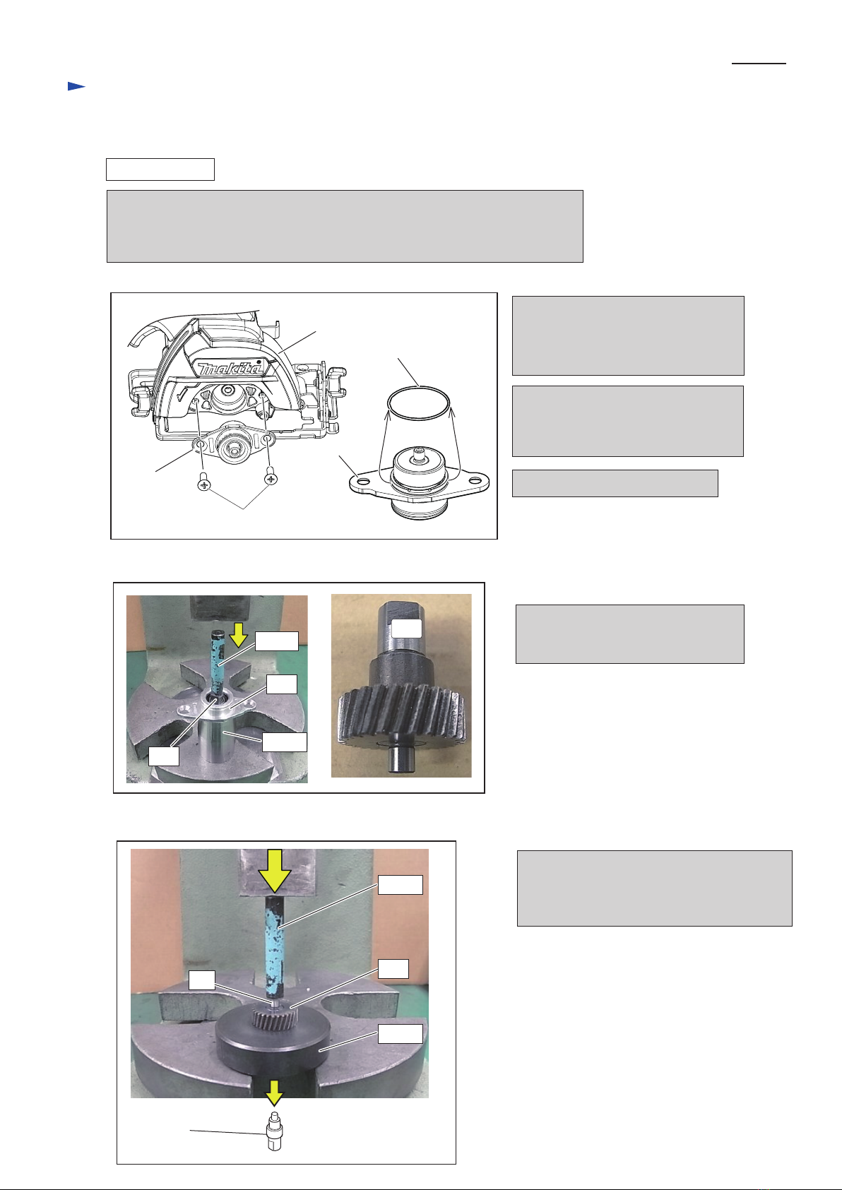
[1] NECESSARY REPAIRING TOOLS
Code No. Description Use for
1R003 removing Retaining ring WR-26
1R027 press fitting Ball bearing 606ZZ
1R028
1R033
1R035
1R037
1R041
1R164
1R212
1R269
1R278
1R282
1R283
RETAINING RING PLIERS ST-2N
BEARING SETTING PIPE 18-10.2
BEARING SETTING PIPE 20-12.2
BEARING SETTING PLATE 10.2
BEARING SETTING PLATE 15.2
BEARING SETTING PLATE 20.2
VISE PLATE
RING SPRING SETTING TOOL A
TIP FOR RETAINING RING PLIERS
BEARING EXTRACTOR
ROUND BAR FOR ARBOR 4-50
ROUND BAR FOR ARBOR 8-50
ROUND BAR FOR ARBOR 9-50
1R356 BEARING PLATE 10MM
1R361 BEARING RETAINER TIGHTEN' TOOL
press fitting Helical gear 28
removing Helical gear 28
removing Helical gear 47
protecting Bearing box from crack
removing Spindle, Helical gear 28
together with 1R003
removing Ball bearing 606ZZ
removing Helical gear 47, Ball bearing 606ZZ
removing Helical gear 28
removing Spindle, Helical gear 28
removing Ball bearing 604ZZ
disassembling / assembling Bearing retainer 14-23
press fitting Helical gear 47 and Helical gear 28
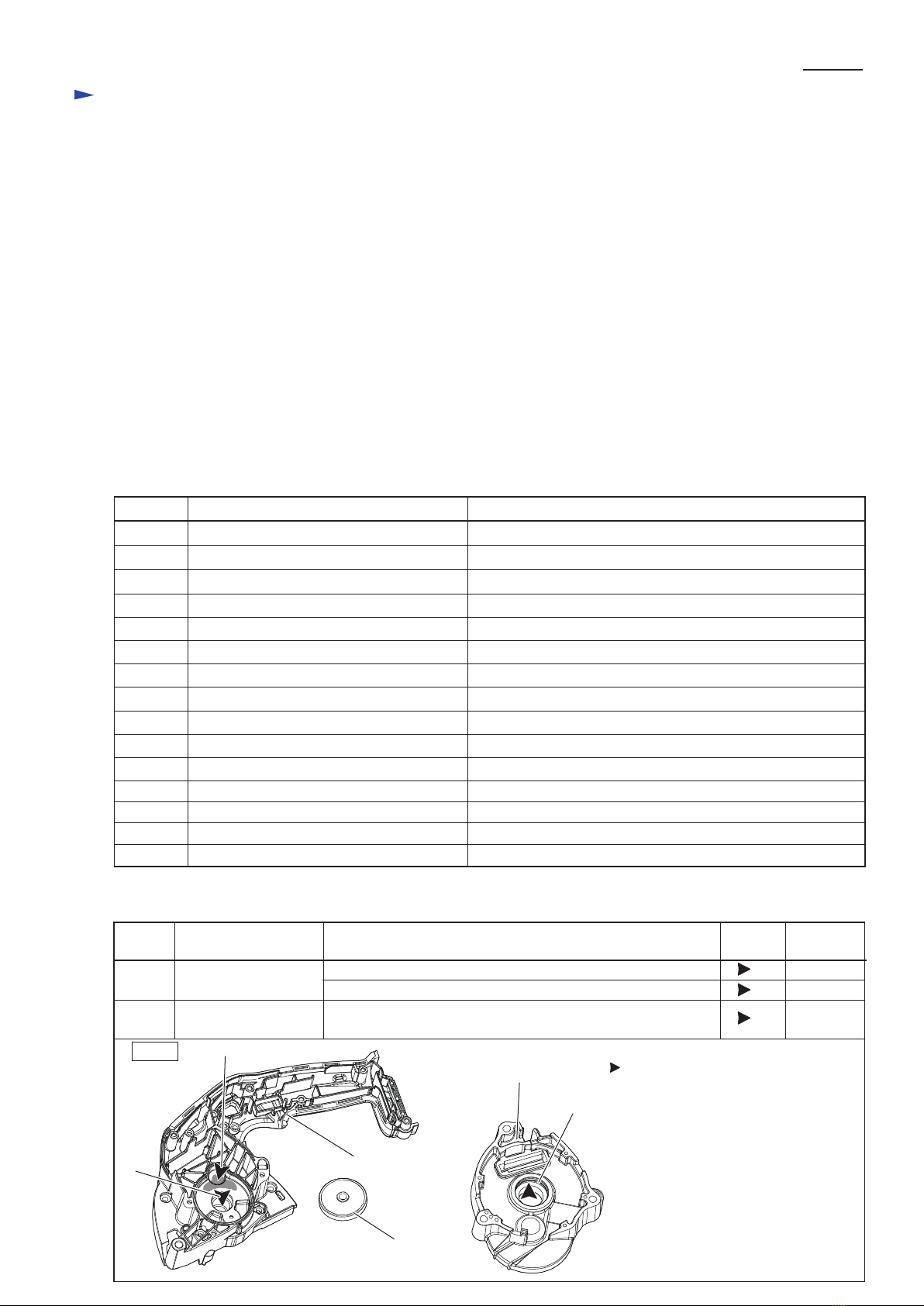
[2] LUBRICATION
Fig. 1
Item No. Description
Handle set R A: Portion in Gear room where Helical gear 47 (26) rotates
B: Hole for Spindle in Gear room
a little
3 g
1 g
(23c) O ring 19 which is a component parts
of Gear housing (23)
Gear housing
Amount
Symbol of
lubricant
Portion to lubricate
Apply Makita grease FA. No.2 to the parts designated with black triangle.
(17)
(17)
(23)
(23)
(26)
(23c)
Makita grease FA. No.2
CAUTION: Repair the machine in accordance with “Instruction manual” or “Safety instructions”.
Index
A
B
[1] NECESSARY REPAIRING TOOLS
[2] LUBRICATION
[3]-1 Tightening torque for Screws
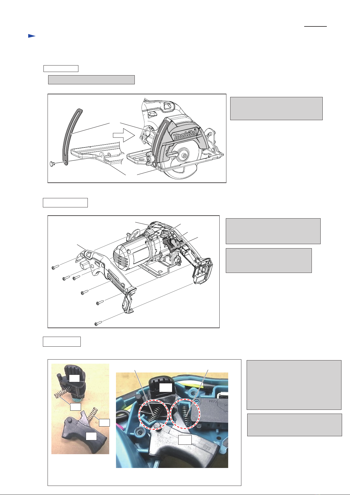
[3]-2. Base
[3]-3. Lock off lever, Switch lever
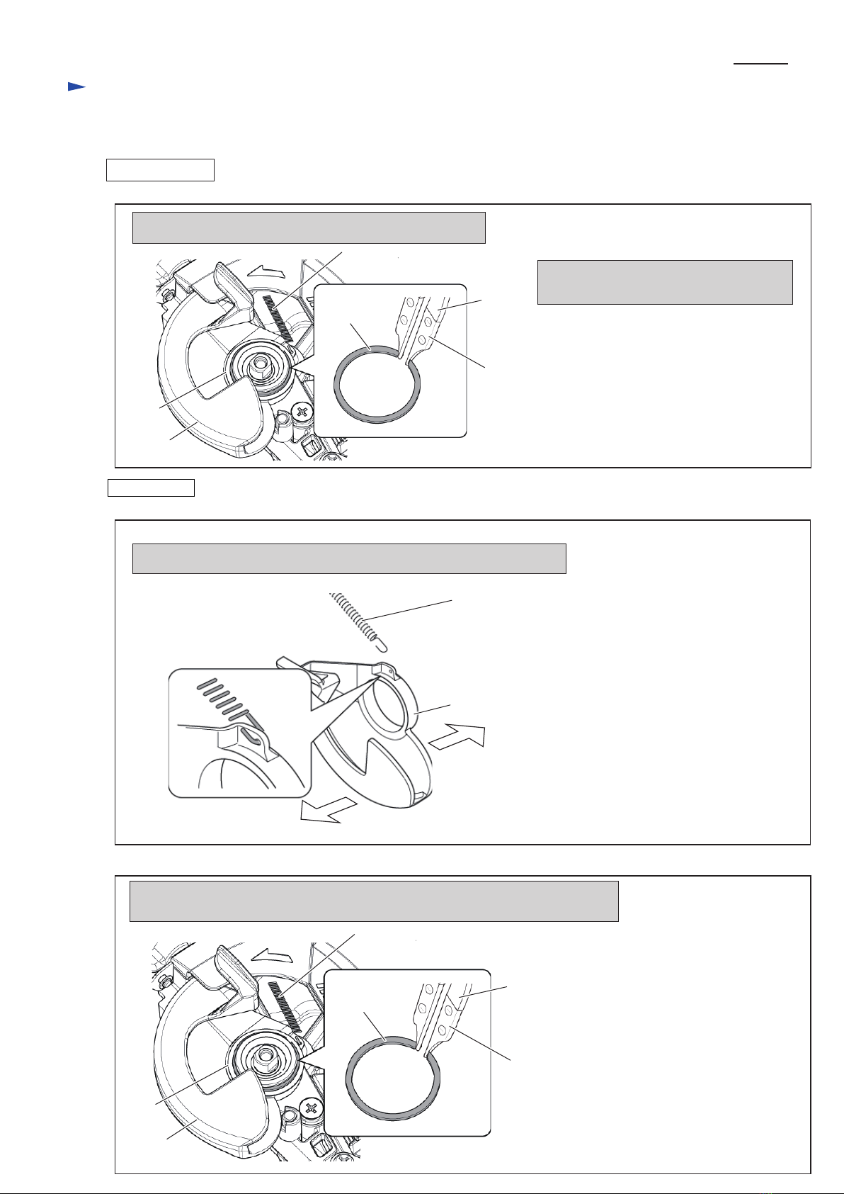
[3]-4. Safety cover
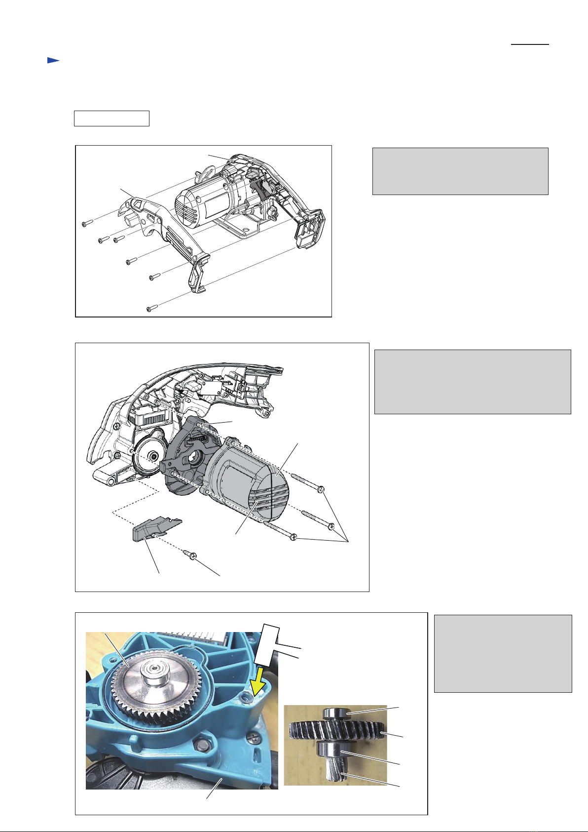
[3]-5. Helical gear 47, Helical gear 9B,
Ball bearing 606ZZ, Ball bearing 604ZZ
[3]-6. Helical gear 28, Ball bearing 6900DDW
[3]-7. DC Motor
* Circuit diagram
* Wiring diagram
Wiring to DC Motor, Wiring in Motor housing
* Wiring of Controller unit
* Wiring in Handle set R
P 2
P 3
P 3-4
P 5
P 6-8
P 9-13
P 13
P 14
P 15
P 16
P 17