Makita JV100D User manual

GB
Cordless Jig Saw Instruction Manual
F
Scie sauteuse sans fil Manuel d’instructions
D
Akku-Stichsäge Betriebsanleitung
I
Seghetto alternativo a batteria Istruzioni per l’uso
NL
Snoerloze figuurzaag Gebruiksaanwijzing
E
Sierra Cacadora Inalámbrica Manual de instrucciones
P
Serra Tico-Tico a Bateria Manual de instruções
DK
Akku-pendulstiksav Brugsanvisning
GR Ασύρματο παλινδρομικό πριόνι Οδηγίες χρήσεως
TR Kablosuz oyma testeresi Kullanma Kılavuzu
JV100D

2
12
4
35
67
12
11
8
7
9
10
4
5
A
B
6
7
8
1
2
3
012335 012312
012314
012313 012315
012316 012318

3
89
10 11
12 13
14 15
15 16
8
7
14
13
14
17
78
14
012319 012320
012321 012322
012323 012324
012325 012326

4
16 17
18 19
20 21
21
25
23
19
20
19
21
22
7
20 8
19
19
12
18
23
24
012327 012328
012329 012330
012331 012333
012334

5
ENGLISH (Original instructions)
Explanation of general view
1 Battery
2 Buttons
3 Cutting action changing lever
4 Lock-off button
5 Switch trigger
6 Blade holder
7Bolt
8Hexwrench
9Blade
10 Roller
11 Hook
12 Dust cover
13 Cutting line
14 Base
15 Edge
16 Graduation
17 Starting hole
18 Hose
19 Rip fence (Guide rule)
20 Fence guide
21 Threaded knob
22 Pin
23 Aluminum base
24 Anti-splintering device
25 Cover plate
SPECIFICATION
• Due to our continuing programme of research and
development, the specifications herein are subject to
change without notice.
• Specifications and battery cartridge may differ from
country to country.
• Weight, with battery cartridge, according to EPTA-Pro-
cedure 01/2003
ENE019-1
Intended use
The tool is intended for the sawing of wood, plastic and
metal materials. As a result of the extensive accessory
and saw blade program, the tool can be used for many
purposes and is very well suited for curved or circular
cuts.
GEA010-1
General Power Tool Safety Warnings
WARNING Read all safety warnings and all
instructions. Failure to follow the warnings and
instructions may result in electric shock, fire and/or
serious injury.
Save all warnings and instructions for future refer-
ence.
GEB045-2
CORDLESS JIG SAW SAFETY WARNINGS
1. Hold power tool by insulated gripping surfaces,
when performing an operation where the cutting
accessory may contact hidden wiring. Cutting
accessory contacting a “live” wire may make
exposed metal parts of the power tool “live” and
could give the operator an electric shock.
2. Use clamps or another practical way to secure
and support the workpiece to a stable platform.
Holding the work by hand or against your body
leaves it unstable and may lead to loss of control.
3. Always use safety glasses or goggles. Ordinary
eye or sun glasses are NOT safety glasses.
4. Avoid cutting nails. Inspect workpiece for any
nails and remove them before operation.
5. Do not cut oversize workpiece.
6. Check for the proper clearance beyond the work-
piece before cutting so that the blade will not
strike the floor, workbench, etc.
7. Hold the tool firmly.
8. Make sure the blade is not contacting the work-
piece before the switch is turned on.
9. Keep hands away from moving parts.
10. Do not leave the tool running. Operate the tool
only when hand-held.
11. Always switch off and wait for the blade to come
to a complete stop before removing the blade
from the workpiece.
12. Do not touch the blade or the workpiece immedi-
ately after operation; they may be extremely hot
and could burn your skin.
13. Do not operate the tool at no-load unnecessarily.
14. Some material contains chemicals which may be
toxic. Take caution to prevent dust inhalation
and skin contact. Follow material supplier safety
data.
15. Always use the correct dust mask/respirator for
the material and application you are working
with.
SAVE THESE INSTRUCTIONS.
Model JV100D
Length of stroke 18 mm
Strokes per minute (min–1) 0 – 2,400
Blade type B type
Max. cutting capacities
Wood 65 mm
Mild steel 2 mm
Aluminium 4 mm
Overall length 231 mm
Net weight 1.7 kg
Rated voltage D.C. 10.8 V

6
WARNING:
DO NOT let comfort or familiarity with product
(gained from repeated use) replace strict adherence
to safety rules for the subject product. MISUSE or
failure to follow the safety rules stated in this instruc-
tion manual may cause serious personal injury.
ENC009-1
IMPORTANT SAFETY INSTRUCTIONS
FOR BATTERY CARTRIDGE
1. Before using battery cartridge, read all instruc-
tions and cautionary markings on (1) battery
charger, (2) battery, and (3) product using bat-
tery.
2. Do not disassemble battery cartridge.
3. If operating time has become excessively
shorter, stop operating immediately. It may
result in a risk of overheating, possible burns
and even an explosion.
4. If electrolyte gets into your eyes, rinse them out
with clear water and seek medical attention right
away. It may result in loss of your eyesight.
5. Do not short the battery cartridge:
(1) Do not touch the terminals with any conduc-
tive material.
(2) Avoid storing battery cartridge in a container
with other metal objects such as nails, coins,
etc.
(3) Do not expose battery cartridge to water or
rain.
A battery short can cause a large current flow,
overheating, possible burns and even a break-
down.
6. Do not store the tool and battery cartridge in
locations where the temperature may reach or
exceed 50°C (122°F).
7. Do not incinerate the battery cartridge even if it
is severely damaged or is completely worn out.
The battery cartridge can explode in a fire.
8. Be careful not to drop or strike battery.
9. Do not use a damaged battery.
SAVE THESE INSTRUCTIONS.
Tips for maintaining maximum battery life
1. Charge the battery cartridge before completely
discharged.
Always stop tool operation and charge the bat-
tery cartridge when you notice less tool power.
2. Never recharge a fully charged battery cartridge.
Overcharging shortens the battery service life.
3. Charge the battery cartridge with room tempera-
ture at 10°C – 40°C (50°F – 104°F). Let a hot bat-
tery cartridge cool down before charging it.
FUNCTIONAL DESCRIPTION
CAUTION:
• Always be sure that the tool is switched off and the bat-
tery cartridge is removed before adjusting or checking
function on the tool.
Installing or removing battery cartridge (Fig. 1)
• Always switch off the tool before installing or removing
of the battery cartridge.
• To remove the battery cartridge, withdraw it from the
tool while pressing the buttons on both sides of the car-
tridge.
• To install the battery cartridge, hold it so that the battery
cartridge front shape fits to that of the battery install-
ment opening and slip it into place. Always insert it all
the way until it locks in place with a little click. If not, it
may accidentally fall out of the tool, causing injury to
you or someone around you.
• Do not use force when installing the battery cartridge. If
the cartridge does not slide in easily, it is not being
inserted correctly.
Battery protection system
The tool is equipped with a battery protection system.
This system automatically cuts off power to the motor to
extend battery life.
The tool will automatically stop during operation if the
tool and/or battery are placed under one of the following
conditions:
• Overloaded:
The tool is operated in a manner that causes it to
draw an abnormally high current. In this situation,
release the trigger switch on the tool and stop the
application that caused the tool to become over-
loaded. Then pull the trigger switch again to restart.
• Low battery voltage:
The remaining battery capacity is too low and the
tool will not operate. If you pull the switch trigger, the
motor runs again but stops soon. In this situation,
remove and recharge the battery.
Selecting the cutting action (Fig. 2)
This tool can be operated with an orbital or a straight line
(up and down) cutting action. The orbital cutting action
thrusts the blade forward on the cutting stroke and
greatly increases cutting speed.
To change the cutting action, just turn the cutting action
changing lever to the desired cutting action position.
Refer to the table to select the appropriate cutting action.
Position Cutting action Applications
0Straight line
cutting action
For cutting mild steel,
stainless steel and
plastics.
For clean cuts in wood and
plywood.
ISmall orbit cut-
ting action
For cutting mild steel,
aluminum and hard wood.
II Medium orbit
cutting action
For cutting wood and
plywood.
For fast cutting in
aluminum and mild steel.
III Large orbit cut-
ting action
For fast cutting in wood
and plywood.

7
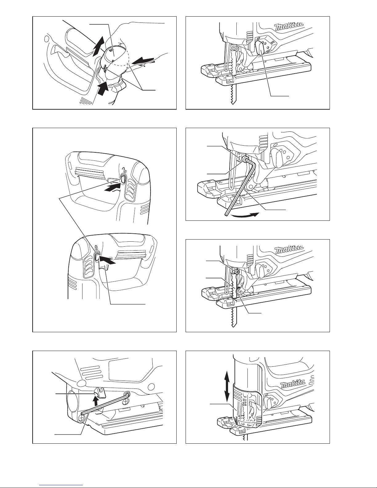
Switch action (Fig. 3)
CAUTION:
• Before installing the battery cartridge into the tool,
always check to see that the switch trigger actuates
properly and returns to the “OFF” position when
released.
• When not operating the tool, depress the lock-off but-
ton from A side to lock the switch trigger in the OFF
position.
To prevent the switch trigger from accidentally pulled, the
lock-off button is provided.
To start the tool, depress the lock-off button from B side
and pull the switch trigger.
Tool speed is increased by increasing pressure on the
switch trigger. Release the switch trigger to stop. After
use, always press in the lock-off button from A side.
ASSEMBLY
CAUTION:
• Always be sure that the tool is switched off and the bat-
tery cartridge is removed before carrying out any work
on the tool.
Installing or removing saw blade (Fig. 4 & 5)
CAUTION:
• Always clean out all chips or foreign matter adhering to
the blade and/or blade holder. Failure to do so may
cause insufficient tightening of the blade, resulting in a
serious personal injury.
• Do not touch the blade or the workpiece immediately
after operation; they may be extremely hot and could
burn your skin.
• Always secure the blade firmly. Insufficient tightening of
the blade may cause blade breakage or serious per-
sonal injury.
• Use only B type blades. Using blades other than B type
blades causes insufficient tightening of the blade,
resulting in a serious personal injury.
To install the blade, loosen the bolt counterclockwise on
the blade holder with the hex wrench.
With the blade teeth facing forward, insert the blade into
the blade holder as far as it will go. Make sure that the
back edge of the blade fits into the roller. Then tighten the
bolt clockwise to secure the blade.
To remove the blade, follow the installation procedure in
reverse.
NOTE:
• Occasionally lubricate the roller.
Hex wrench storage (Fig. 6)
When not in use, store the hex wrench as shown in the
figure to keep it from being lost.
First, insert the hex wrench into the hole. Then push it
into the hook until it locked.
Dust cover (Fig. 7)
CAUTION:
• Always wear safety goggles even when operating the
tool with the dust cover lowered.
Lower the dust cover to prevent chips from flying. How-
ever, when making bevel cuts, raise it all the way.
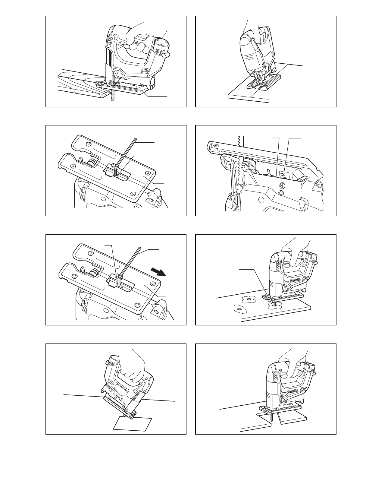
OPERATION
CAUTION:
• Always hold the base flush with the workpiece. Failure
to do so may cause blade breakage, resulting in a seri-
ous injury.
• Advance the tool very slowly when cutting curves or
scrolling. Forcing the tool may cause a slanted cutting
surface and blade breakage.
Turn the tool on without the blade making any contact
and wait until the blade attains full speed. Then rest the
tool base flat on the workpiece and gently move the tool
forward along the previously marked cutting line. (Fig. 8)
Bevel cutting (Fig. 9, 10 & 11)
CAUTION:
• Always be sure that the tool is switched off and the bat-
tery cartridge is removed before tilting the base.
• Raise the dust cover all the way before making bevel
cuts.
With the base tilted, you can make bevel cuts at any
angle between 0° and 45° (left or right).
Loosen the bolt on the back of the base with the hex
wrench. Move the tool base so that the bolt is positioned
in the center of the cross-shaped slot in the base.
Tilt the base until the desired bevel angle is obtained.
The edge of the motor housing indicates the bevel angle
by graduations. Then tighten the bolt to secure the base.
Front flush cuts (Fig. 12)
Loosen the bolt on the back of the tool base with the hex
wrench, and slide the base all the way back. Then tighten
the bolt to secure the tool base.
Cutouts
Cutouts can be made with either of two methods A or B.
A) Boring a starting hole (Fig. 13)
For internal cutouts without a lead-in cut from an
edge, pre-drill a starting hole 12 mm or more in diam-
eter. Insert the blade into this hole to start your cut.
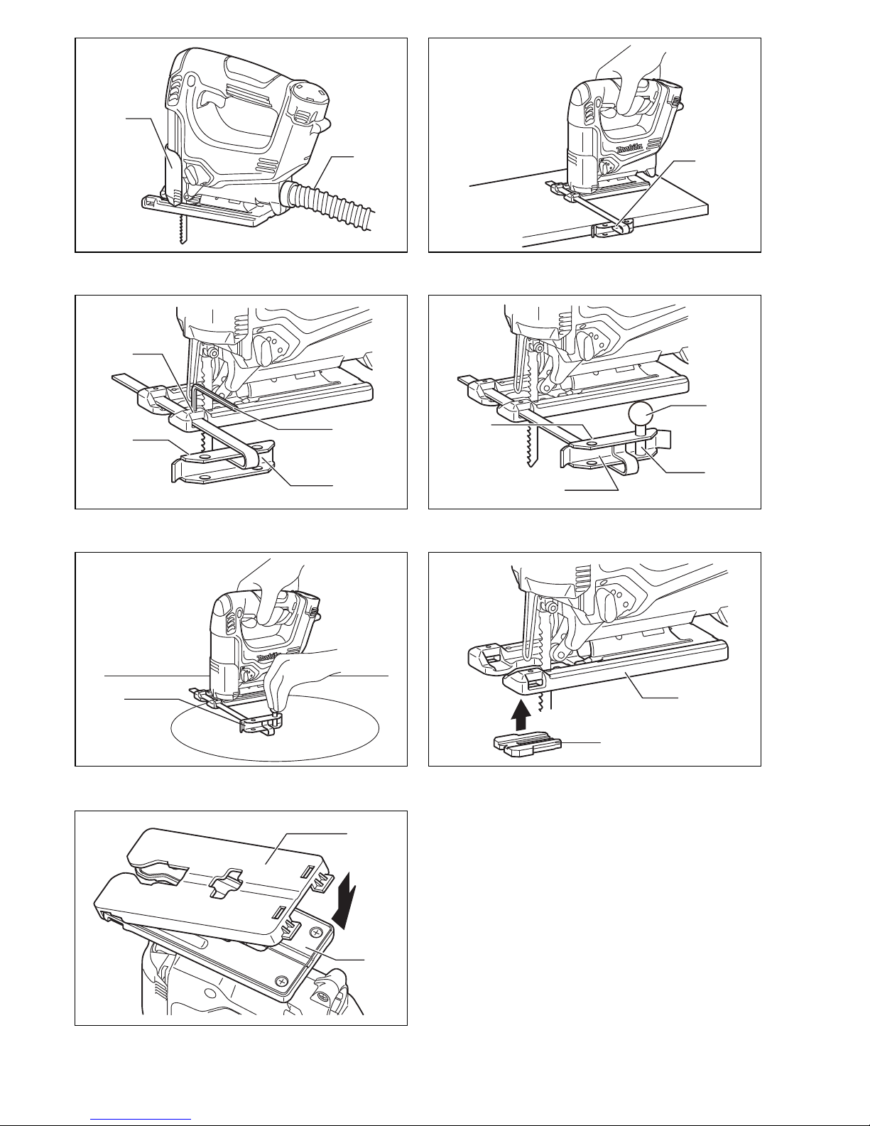
B) Plunge cutting (Fig. 14)
You need not bore a starting hole or make a lead-in
cut if you carefully do as follows.
1. Tilt the tool up on the front edge of the base with
the blade point positioned just above the work-
piece surface.
2. Apply pressure to the tool so that the front edge of
the base will not move when you switch on the tool
and gently lower the back end of the tool slowly.
3. As the blade pierces the workpiece, slowly lower
the base of the tool down onto the workpiece sur-
face.
4. Complete the cut in the normal manner.
Finishing edges (Fig. 15)
To trim edges or make dimensional adjustments, run the
blade lightly along the cut edges.
Metal cutting
Always use a suitable coolant (cutting oil) when cutting
metal. Failure to do so will cause significant blade wear.
The underside of the workpiece can be greased instead
of using a coolant.

8
Dust extraction (Fig. 16)
Clean cutting operations can be performed by connect-
ing this tool to a Makita vacuum cleaner. Insert the hose
of the vacuum cleaner into the hole at the rear of the tool.
Lower the dust cover before operation.
NOTE:
• Dust extraction cannot be performed when making
bevel cuts.
Rip fence (optional accessory)
CAUTION:
• Always be sure that the tool is switched off and the bat-
tery cartridge is removed before installing or removing
accessories.
1) Straight cuts (Fig. 17 & 18)
When repeatedly cutting widths of 160 mm or less,
use of the rip fence will assure fast, clean, straight
cuts.
To install, insert the rip fence into the rectangular hole
on the side of the base with the fence guide facing
down. Slide the rip fence to the desired cutting width
position, then tighten the bolt to secure it.
2) Circular cuts (Fig. 19 & 20)
When cutting circles or arcs of 170 mm or less in
radius, install the rip fence as follows.
Insert the rip fence into the rectangular hole on the
side of the base with the fence guide facing up. Insert
the circular guide pin through either of the two holes
on the fence guide. Screw the threaded knob onto the
pin to secure the pin.
Now slide the rip fence to the desired cutting radius,
and tighten the bolt to secure it in place. Then move
the tool base all the way forward.
NOTE:
• Always use blades No. B-17, B-18, B-26 or B-27 when
cutting circles or arcs.
Anti-splintering device (optional accessory)
(Fig. 21)
For splinter-free cuts, the anti-splintering device can be
used. To install the anti-splintering device, move the tool
base all the way forward and fit it from the back of tool
base. When you use the cover plate, install the anti-splin-
tering device onto the cover plate.
CAUTION:
• The anti-splintering device cannot be used when mak-
ing bevel cuts.
Cover plate (optional accessory) (Fig. 22)
Use the cover plate when cutting decorative veneers,
plastics, etc. It protects sensitive or delicate surfaces
from damage. Fit it on the back of the tool base.
MAINTENANCE
CAUTION:
• Always be sure that the tool is switched off and the bat-
tery cartridge is removed before attempting to perform
inspection or maintenance.
• Never use gasoline, benzine, thinner, alcohol or the
like. Discoloration, deformation or cracks may result.
To maintain product SAFETY and RELIABILITY, repairs,
any other maintenance or adjustment should be per-
formed by Makita Authorized Service Centers, always
using Makita replacement parts.
OPTIONAL ACCESSORIES
CAUTION:
• These accessories or attachments are recommended
for use with your Makita tool specified in this manual.
The use of any other accessories or attachments might
present a risk of injury to persons. Only use accessory
or attachment for its stated purpose.
If you need any assistance for more details regarding
these accessories, ask your local Makita Service Center.
• Jig saw blades
• Hex wrench 3
• Rip fence (guide rule) set
• Anti-splintering device
• Hose (For vacuum cleaner)
• Cover plate (For aluminum base type)
• Various type of Makita genuine batteries and chargers
NOTE:
• Some items in the list may be included in the tool pack-
age as standard accessories. They may differ from
country to country.
ENG905-1
Noise
The typical A-weighted noise level determined according
to EN60745:
Sound pressure level (LpA): 76 dB (A)
Uncertainty (K): 3 dB (A)
The noise level under working may exceed 80 dB (A).
Wear ear protection
ENG900-1
Vibration
The vibration total value (tri-axial vector sum) determined
according to EN60745:
Work mode: cutting boards
Vibration emission (ah, B): 10.5 m/s2
Uncertainty (K): 2.5 m/s2
Work mode: cutting sheet metal
Vibration emission (ah, M): 7.5 m/s2
Uncertainty (K): 1.5 m/s2
ENG901-1
• The declared vibration emission value has been mea-
sured in accordance with the standard test method and
may be used for comparing one tool with another.
• The declared vibration emission value may also be
used in a preliminary assessment of exposure.
WARNING:
• The vibration emission during actual use of the power
tool can differ from the declared emission value
depending on the ways in which the tool is used.
• Be sure to identify safety measures to protect the oper-
ator that are based on an estimation of exposure in the
actual conditions of use (taking account of all parts of
the operating cycle such as the times when the tool is
switched off and when it is running idle in addition to
the trigger time).

9
ENH101-15
For European countries only
EC Declaration of Conformity
We Makita Corporation as the responsible
manufacturer declare that the following Makita
machine(s):
Designation of Machine:
Cordless Jig Saw
Model No./ Type: JV100D
are of series production and
Conforms to the following European Directives:
2006/42/EC
And are manufactured in accordance with the following
standards or standardised documents:
EN60745
The technical documentation is kept by our authorized
representative in Europe who is:
Makita International Europe Ltd.
Michigan Drive, Tongwell,
Milton Keynes, Bucks MK15 8JD, England
26.4.2011
Tomoyasu Kato
Director
Makita Corporation
3-11-8, Sumiyoshi-cho,
Anjo, Aichi, 446-8502, JAPAN

26
NEDERLANDS (Originele instructies)
Verklaring van algemene gegevens
1Accu
2 Knoppen
3 Zaagactie-keuzehendel
4 Vastzetknop
5 Trekkerschakelaar
6 Zaagbladhouder
7 Bout
8 Inbussleutel
9 Zaagblad
10 Rol
11 Haak
12 Stofkap
13 Zaaglijn
14 Voet
15 Zijrand
16 Schaalverdelingen
17 Startgaatje
18 Slang
19 Breedtegeleider
(trekgeleider-set)
20 Geleider
21 Schroefknop
22 Pen
23 Aluminiumvoet
24 Antisplinterinrichting
25 Dekplaat
TECHNISCHE GEGEVENS
• In verband met ononderbroken research en ontwikke-
ling behouden wij ons het recht voor bovenstaande
technische gegevens te wijzigen zonder voorafgaande
kennisgeving.
• De technische gegevens en de uitvoering van de accu
kunnen verschillen van land tot land.
• Gewicht, inclusief accu, volgens EPTA-procedure 01/
2003
ENE019-1
Doeleinden van gebruik
Dit gereedschap is bedoeld voor het zagen van hout,
kunststof en metalen materialen. Een uitgebreide keuze
van accessoires en zaagbladen staat ter beschikking,
zodat het gereedschap voor talrijke doeleinden kan wor-
den gebruikt en optimaal geschikt is voor het zagen van
bogen en cirkels.
GEA010-1
Algemene veiligheidswaarschuwingen voor
elektrisch gereedschap
WAARSCHUWING! Lees alle veiligheidswaar-
schuwingen en alle instructies. Het niet volgen van de
waarschuwingen en instructies kan leiden tot elektrische
schokken, brand en/of ernstig letsel.
Bewaar alle waarschuwingen en instructies om in de
toekomst te kunnen raadplegen.
GEB045-2
VEILIGHEIDSVOORSCHRIFTEN VOOR DE
SNOERLOZE DECOUPEERZAAG
1. Houd elektrisch gereedschap alleen vast aan het
geïsoleerde oppervlak van de handgrepen, wan-
neer u werkt op plaatsen waar het zaagblad met
verborgen bedrading in aanraking kan komen.
Wanneer het zaagaccessoire in aanraking komen
met onder spanning staande draden, zullen de niet-
geïsoleerde metalen delen van het gereedschap
onder spanning komen te staan zodat de gebruiker
een elektrische schok kan krijgen.
2. Gebruik klemmen of een andere praktische
methode om het werkstuk op een stabiele onder-
grond te bevestigen en ondersteunen. Als u het
werkstuk in uw hand of tegen uw lichaam geklemd
houdt, is het onvoldoende stabiel en kunt u de con-
trole erover verliezen.
3. Draag altijd een veiligheidsbril. Een gewone bril
of een zonnebril is GEEN veiligheidsbril.
4. Vermijd het zagen op spijkers. Inspecteer het
werkstuk vooraf op de aanwezigheid van spij-
kers en verwijder deze voordat u met het werk
begint.
5. Zaag geen werkstukken die te groot zijn.
6. Controleer vooraf of er voldoende vrije ruimte is
achter het werkstuk om te voorkomen dat het
zaagblad tegen een vloer, een werkbank e.d.
stoot.
7. Houd het gereedschap stevig vast.
8. Zorg ervoor dat het zaagblad niet in contact is
met het werkstuk voordat u de spanning inscha-
kelt.
Model JV100D
Slaglengte 18 mm
Aantal slagen per minuut (min–1) 0 – 2 400
Type zaagblad Type B
Max. zaagcapaciteit
Hout 65 mm
Zacht staal 2 mm
Aluminium 4 mm
Totale lengte 231 mm
Nettogewicht 1,7 kg
Nominale spanning Gelijkstroom 10,8 V

27
9. Houd uw handen uit de buurt van de bewegende
delen.
10. Schakel altijd het gereedschap uit als u weg
moet. Schakel het gereedschap alleen in als u
het in handen houdt.
11. Schakel altijd uit en wacht tot het zaagblad volle-
dig tot stilstand is gekomen, alvorens het
gereedschap van het werkstuk te verwijderen.
12. Raak onmiddellijk na gebruik het zaagblad of het
werkstuk niet aan, aangezien het nog gloeiend
heet kan zijn en brandwonden kan veroorzaken.
13. Laat het gereedschap niet onnodig onbelast
draaien.
14. Sommige materialen bevatten chemische stoffen
die giftig kunnen zijn. Vermijd inademing van
stof en contact met de huid. Volg de veiligheids-
instructies van de leverancier van het materiaal.
15. Gebruik altijd het juiste stofmasker/ademha-
lingsapparaat voor het materiaal en de toepas-
sing waarmee u werkt.
BEWAAR DEZE VOORSCHRIFTEN.
WAARSCHUWING:
Laat u NIET misleiden door een vals gevoel van com-
fort en bekendheid met het gereedschap (na veelvul-
dig gebruik) en neem alle veiligheidsvoorschriften
van het betreffende gereedschap altijd strikt in acht.
VERKEERD GEBRUIK of het niet naleven van de vei-
ligheidsvoorschriften in deze gebruiksaanwijzing
kan leiden tot ernstige persoonlijke verwonding.
ENC009-1
BELANGRIJKE VEILIGHEIDSVOORSCHRIFTEN
VOOR ACCU
1. Lees alle voorschriften en waarschuwingen op
(1) de acculader, (2) de accu, en (3) het product
waarvoor de accu wordt gebruikt, aandachtig
door alvorens de accu in gebruik te nemen.
2. Neem de accu niet uit elkaar.
3. Als de gebruikstijd van een opgeladen accu aan-
zienlijk korter is geworden, moet u het gebruik
ervan onmiddellijk stopzetten. Voortgezet
gebruik kan oververhitting, brandwonden en
zelfs een ontploffing veroorzaken.
4. Als er elektrolyt in uw ogen is terechtgekomen,
spoel dan uw ogen met schoon water en roep
onmiddellijk de hulp van een dokter in. Elektrolyt
in de ogen kan blindheid veroorzaken.
5. Voorkom kortsluiting van de accu:
(1) Raak de accuklemmen nooit aan met een
geleidend materiaal.
(2) Bewaar de accu niet in een bak waarin
andere metalen voorwerpen zoals spijkers,
munten e.d. worden bewaard.
(3) Stel de accu niet bloot aan water of regen.
Kortsluiting van de accu kan oorzaak zijn van
een grote stroomafgifte, oververhitting, brand-
wonden, en zelfs defecten.
6. Bewaar het gereedschap en de accu niet op
plaatsen waar de temperatuur kan oplopen tot
50°C of hoger.
7. Werp de accu nooit in het vuur, ook niet wanneer
hij zwaar beschadigd of volledig versleten is. De
accu kan namelijk ontploffen in het vuur.
8. Wees voorzichtig dat u de accu niet laat vallen
en hem niet blootstelt aan schokken of stoten.
9. Gebruik nooit een beschadigde accu.
BEWAAR DEZE VOORSCHRIFTEN.
Tips voor een maximale levensduur van de accu
1. Laad de accu op voordat hij volledig ontladen is.
Stop het gebruik van het gereedschap en laad de
accu op telkens wanneer u vaststelt dat het ver-
mogen van het gereedschap is afgenomen.
2. Laad een volledig opgeladen accu nooit opnieuw
op. Als u de accu te veel oplaadt, zal hij minder
lang meegaan.
3. Laad de accu op bij een kamertemperatuur tus-
sen 10°C en 40°C. Laat een warme accu afkoelen
alvorens hem op te laden.
BESCHRIJVING VAN DE FUNCTIES
LET OP:
• Zorg altijd dat het gereedschap is uitgeschakeld en de
accu ervan is verwijderd alvorens de functies op het
gereedschap af te stellen of te controleren.
Installeren of verwijderen van de accu (Fig. 1)
• Schakel het gereedschap altijd uit alvorens de accu te
installeren of te verwijderen.
• Om de accu te verwijderen, schuift u die uit het gereed-
schap terwijl u de knoppen aan weerszijden van de
accu ingedrukt houdt.
• Om de accu aan te brengen, houdt u die zo dat de
vorm past in de accu-insteekopening en dan schuift u
de accu er in. Schuif de accu er altijd volledig in totdat
die op zijn plaats vastklikt. Als u dit nalaat, zou de accu
uit het gereedschap kunnen vallen en uzelf of anderen
kunnen verwonden.
• Probeer nooit om de accu met kracht te installeren. Als
de accu er niet gemakkelijk ingaat, betekent dit dat u
hem niet op de juiste wijze erin steekt.
Accubeveiligingssysteem
Dit gereedschap is voorzien van een accubeveiligings-
systeem. Dat kan automatisch de stroomtoevoer naar de
motor afsluiten om de levensduur van de accu te verlen-
gen.
Het gereedschap stopt tijdens gebruik automatisch wan-
neer het gereedschap en/of de accu aan één van de vol-
gende omstandigheden wordt blootgesteld:
• Overbelasting:
Als het gereedschap wordt gebruikt op een manier
die een abnormaal hoge stroomsterkte vergt. In dat
geval laat u de trekschakelaar van het gereedschap
los en verhelpt u de oorzaak van de overbelasting.
Vervolgens drukt u de trekschakelaar weer in om het
gereedschap te herstarten.
• Onvoldoende accuspanning:
De resterende accuspanning is onvoldoende, zodat
het gereedschap niet meer werkt. Wanneer u de
trekkerschakelaar indrukt, start de motor even, maar
slaat al gauw weer af. In dit geval verwijdert u de
accu en laadt u die opnieuw op.

28
Selecteren van de zaagactie (Fig. 2)
Dit gereedschap kan met twee zaagacties worden
gebruikt: zagen in een cirkelbaan of in rechte lijn (op en
neer). Tijdens zagen in een cirkelbaan, wordt het zaag-
blad door de zaagactie naar voren geduwd en vermeer-
dert de zaagsnelheid aanzienlijk.
Om de zaagactie te veranderen, draait u gewoon de
zaagactie-keuzehendel naar de gewenste stand.
Zie de tabel om de juiste zaagwerking te kiezen.
Werking van de schakelaar (Fig. 3)
LET OP:
• Alvorens de accu in het gereedschap te installeren,
controleert u eerst of de trekkerschakelaar goed werkt
en na loslaten terugkeert naar de uit-stand.
• Wanneer u het gereedschap niet gebruikt, drukt u op
de uitstand-borgknop vanaf de A-kant om de trekker-
schakelaar te vergrendelen in de uit-stand.
Om per ongeluk indrukken van de trekkerschakelaar te
voorkomen, is er voorzien in een vastzetknop.
Om het gereedschap te starten, drukt u de vastzetknop
in vanaf kant B en drukt u de trekkerschakelaar in.
De snelheid van het gereedschap wordt hoger, naarmate
u de trekkerschakelaar harder indrukt. Laat de trekker-
schakelaar los om te stoppen. Na het gebruik drukt u
altijd de vastzetknop in vanaf kant A.
INEENZETTEN
LET OP:
• Zorg altijd dat het gereedschap is uitgeschakeld en de
accu is verwijderd, alvorens u enig werk aan het
gereedschap gaat verrichten.
Installeren of verwijderen van het zaagblad
(Fig. 4 en 5)
LET OP:
• Verwijder altijd alle spaanders of verontreinigingen van
het zaagblad en/of de zaagbladhouder. Als u dit ver-
zuimt, bestaat er kans dat het zaagblad niet goed vast-
gezet zal zijn, hetgeen ernstige verwonding kan
veroorzaken.
• Raak het zaagblad of het werkstuk niet aan onmiddel-
lijk na het gebruik; deze kunnen gloeiend heet zijn en
brandwonden veroorzaken.
• Zet het zaagblad altijd goed vast. Als het zaagblad
onvoldoende goed is vastgezet, kan het breken en ern-
stig persoonlijk letsel ontstaan.
• Gebruik uitsluitend type B zaagbladen. Als u een ander
zaagblad dan type B gebruikt, wordt het zaagblad
onvoldoende goed vastgezet waardoor ernstig per-
soonlijk letsel kan ontstaan.
Om het zaagblad te monteren, draait u de bout op de
zaagbladhouder met de inbussleutel linksom.
Terwijl de tanden van het zaagblad naar voren wijzen,
steekt u het zaagblad zo ver mogelijk in de zaagbladhou-
der. Zorg ervoor dat de achterrand van het zaagblad in
de rol past. Draai daarna de bout rechtsom vast om het
zaagblad vast te zetten.
Om het zaagblad te verwijderen, volgt u de procedure in
omgekeerde volgorde.
OPMERKING:
• Smeer de rol af en toe.
Opbergplaats voor de inbussleutel (Fig. 6)
Wanneer u de inbussleutel niet gebruikt, bergt u deze op
de plaats aangegeven in de afbeelding op, om te voorko-
men dat deze wordt verloren.
Steek eerst de inbussleutel in de opening. Druk hem ver-
volgens in de haak totdat hij vergrendeld is.
Stofkap (Fig. 7)
LET OP:
• Draag altijd een veiligheidsbril, ook wanneer u het
gereedschap gebruikt met de stofkap naar omlaag
gebracht.
Breng de stofkap omlaag om te voorkomen dat spaan-
ders in het rond vliegen. Voor verstekzagen dient u de
stofkap echter helemaal omhoog te brengen.
BEDIENING
LET OP:
• Houd de voet van het gereedschap altijd vlak met het
werkstuk. Als u dit niet doet, kan het zaagblad breken,
hetgeen ernstige verwonding kan veroorzaken.
• Beweeg het gereedschap langzamer vooruit tijdens het
zagen van bochten en bij ornamentzagen. Als u het
gereedschap dwingt, kan een schuin zaagoppervlak
ontstaan en het zaagblad breken.
Schakel het gereedschap in zonder dat het zaagblad iets
raakt en wacht tot het zaagblad op volle snelheid draait.
Plaats dan de voet van het gereedschap vlak op het
werkstuk en beweeg het gereedschap langzaam naar
voren langs de van te voren op het werkstuk aange-
brachte zaaglijn. (Fig. 8)
Stand Zaagactie Toepassingen
0Zagen in rechte
lijn
Zagen van zacht staal,
roestvrij staal en plastic.
Schoon zagen van hout
en gelaagd hout.
IZagen in kleine
cirkelbaan
Zagen van zacht staal,
aluminium en hard hout.
II
Zagen in mid-
delgrote cirkel-
baan
Zagen van hout en
gelaagd hout.
Snel zagen in aluminium
en zacht staal.
III Zagen in grote
cirkelbaan
Snel zagen in hout en
gelaagd hout.

29
Zagen onder een schuine hoek (Fig. 9, 10 en 11)
LET OP:
• Zorg altijd dat het gereedschap is uitgeschakeld en de
accu is verwijderd, alvorens u het voetstuk kantelt.
• Breng de stofkap helemaal omhoog alvorens schuine
zaagsneden te maken.
Door de gereedschapsvoet schuin te zetten kunt u
schuin zagen bij een willekeurige hoek tussen 0° en 45°
(links of rechts).
Draai met de inbussleutel de bout aan de achterkant van
de voet los. Beweeg de voet zodat de bout vlak in het
midden van de kruisvormige sleuf in de voet komt te zit-
ten.
Kantel de gereedschapsvoet om de gewenste schuine
hoek te krijgen. Op de rand van het motorhuis wordt de
verstekhoek aangegeven door een schaalverdeling.
Draai daarna de bout vast om de voet vast te zetten.
Zagen tot helemaal tegen de kant (Fig. 12)
Draai met de inbussleutel de bout aan de achterkant van
de voet los en schuif de voet helemaal naar achteren.
Draai daarna de bout vast om de voet vast te zetten.
Figuren uitzagen
Voor het uitzagen van figuren kunt u methode A of B
gebruiken.
A) Voorboren van een startgaatje (Fig. 13)
Om figuren onmiddellijk in het midden van het werk-
stuk uit te zagen, en dus niet vanaf de rand, dient u
eerst een startgaatje met een diameter van 12 mm of
meer te boren. Steek het zaagblad door dit gaatje en
begin dan met te zagen.
B) Invalzagen (Fig. 14)
U hoeft geen startgaatje te boren of geen geleides-
nede te maken indien u voorzichtig als volgt te werk
gaat.
1. Houd het gereedschap schuin voorover door alleen
de voorrand van de voet op het werkstuk te laten
rusten, met de punt van het zaagblad net boven
het werkstukoppervlak.
2. Oefen een beetje druk uit op het gereedschap om
te voorkomen dat de voorrand van de voet kan
bewegen, en schakel het gereedschap in. Laat het
achterste van het gereedschap langzaam zakken.
3. Naarmate het zaagblad door het werkstuk heen
zaagt, laat u de voet van het gereedschap lang-
zaam op het werkstukoppervlak zakken.
4. Zaag verder op de normale manier.
Afwerken van de randen (Fig. 15)
Voor het afwerken van randen of voor nauwkeurig op
maat zagen, laat u het zaagblad lichtjes langs de
gezaagde randen lopen.
Zagen van metaal
Voor het zagen van metaal dient u altijd een geschikt
koelmiddel (snijolie) te gebruiken. Wanneer u dit niet
doet, zal het zaagblad snel slijten. In plaats van een koel-
middel te gebruiken, kunt u ook de onderkant van het
werkstuk invetten.
Stofafzuiging (Fig. 16)
U kunt schoner werken door dit gereedschap op een
Makita stofzuiger aan te sluiten. Steek de slang van de
stofzuiger in de opening aan de achterkant van het
gereedschap. Breng de stofkap omlaag alvorens het
gereedschap te gebruiken.
OPMERKING:
• Stofafzuiging is niet mogelijk tijdens zagen onder een
schuine hoek.
Breedtegeleider (optioneel accessoire)
LET OP:
• Zorg altijd dat het gereedschap is uitgeschakeld en de
accu is verwijderd, alvorens u accessoires gaat instal-
leren of verwijderen.
1) Rechte stukken zagen (Fig. 17 en 18)
Wanneer u herhaaldelijk stukken die 160 mm of min-
der breed zijn wilt zagen, kunt u snel rechte en
schone sneden krijgen door de breedtegeleider te
gebruiken.
Om de breedtegeleider te installeren, steekt u deze
met zijn geleider naar beneden gericht door de
rechthoekige opening op de zijkant van de gereed-
schapsvoet. Schuif de breedtegeleider naar de posi-
tie van de gewenste breedte, en draai dan de bout
vast om hem vast te zetten.
2) Cirkels en bogen zagen (Fig. 19 en 20)
Wanneer u cirkels of bogen met een straal van
170 mm of minder wilt zagen, dient u de breedtege-
leider als volgt te installeren.
Steek de breedtegeleider met zijn geleider naar
boven gericht door de rechthoekige opening op de
zijkant van de gereedschapsvoet. Steek de pen van
de cirkelgeleider door een van de twee gaatjes in de
geleider. Zet de pen vast door de schroefknop erop
te schroeven.
Schuif nu de breedtegeleider naar de positie van de
gewenste straal, en zet deze vast door de bout vast
te draaien. Schuif daarna de voet van het gereed-
schap helemaal naar voren.
OPMERKING:
• Gebruik altijd zaagbladen Nr. B-17, B-18, B-26 of B-27
wanneer u cirkels of bogen wilt zagen.
Antisplinterinrichting (optioneel accessoire)
(Fig. 21)
Om splintervrije zaagsneden te krijgen, kunt u de anti-
splinterinrichting gebruiken. Om deze te installeren,
schuift u de gereedschapsvoet helemaal naar voren en
dan bevestigt u de inrichting vanaf de onderzijde van de
voet. Wanneer u de dekplaat gebruikt, installeert u de
antisplinterinrichting op de dekplaat.
LET OP:
• De antisplinterinrichting kan niet gebruikt worden voor
zagen onder een schuine hoek.
Dekplaat (optioneel accessoire) (Fig. 22)
• Gebruik de dekplaat wanneer u decoratiefineerhout,
kunststof e.d. zaagt. Deze plaat beschermt gevoelige
of tere oppervlakken tegen beschadiging. Bevestig de
plaat op de onderzijde van de gereedschapsvoet.

30
ONDERHOUD
LET OP:
• Zorg altijd dat het gereedschap is uitgeschakeld en de
accu is verwijderd, alvorens u inspectie of onderhoud
gaat verrichten. Gebruik voor het reinigen nooit ben-
zine, petroleum, spiritus of thinner.
• Gebruik nooit benzine, wasbenzine, thinner, alcohol en
dergelijke. Hierdoor het verkleuring, vervormingen en
barsten worden veroorzaakt.
Om de VEILIGHEID en BETROUWBAARHEID van het
apparaat te waarborgen, moeten reparaties, inwendig
onderhoud en afstellingen worden verricht bij een
bevoegd Makita servicecentrum, met gebruik van origi-
nele Makita vervangingsonderdelen.
OPTIONELE ACCESSOIRES
LET OP:
• Deze accessoires of hulpstukken worden aanbevolen
voor gebruik met het Makita gereedschap dat in deze
gebruiksaanwijzing wordt beschreven. Het gebruik van
andere accessoires of hulpstukken kan gevaar voor
persoonlijke verwonding opleveren. Gebruik de acces-
soires of hulpstukken uitsluitend voor het gespecifi-
ceerde doel.
Wenst u meer informatie over deze accessoires, neem
dan contact op met het dichtstbijzijnde Makita service-
centrum.
• Decoupeerzaagblad
• Inbussleutel 3
• Breedtegeleider-set (trekgeleider-set)
• Antisplinterinrichting
• Slang (voor stofzuiger)
• Dekplaat (voor type met aluminiumvoet)
• Diverse typen originele Makita accu’s en accu-opladers
OPMERKING:
• Sommige van de onderdelen in deze lijst kunnen bijge-
leverd zijn als standaard-accessoires. Deze accessoi-
res kunnen per land verschillend zijn.
ENG905-1
Geluidsniveau
De typisch, A-gewogen geluidsniveaus vastgesteld vol-
gens EN60745:
Geluidsdrukniveau (LpA): 76 dB (A)
Onnauwkeurigheid (K): 3 dB (A)
Tijdens het werken kan het geluidsniveau 80 dB (A) over-
schrijden.
Draag oorbeschermers
ENG900-1
Trilling
De totaalwaarde van de trillingen (triaxiale vectorsom)
vastgesteld volgens EN60745:
Toepassing: zagen in plaatmateriaal
Trillingsemissie (ah, B): 10,5 m/s2
Onnauwkeurigheid (K): 2,5 m/s2
Toepassing: plaatstaal knippen
Trillingsemissie (ah, M): 7,5 m/s2
Onnauwkeurigheid (K): 1,5 m/s2
ENG901-1
• De opgegeven trillingsemissiewaarde is gemeten vol-
gens de standaardtestmethode en kan worden gebruikt
om dit gereedschap te vergelijken met andere gereed-
schappen.
• De opgegeven trillingsemissiewaarde kan ook worden
gebruikt voor een beoordeling vooraf van de blootstel-
ling.
WAARSCHUWING:
• De trillingsemissie tijdens het gebruik van het elektrisch
gereedschap in de praktijk kan verschillen van de
opgegeven trillingsemissiewaarde afhankelijk van de
manier waarop het gereedschap wordt gebruikt.
• Zorg ervoor dat veiligheidsmaatregelen worden getrof-
fen ter bescherming van de operator die zijn gebaseerd
op een schatting van de blootstelling onder praktijkom-
standigheden (rekening houdend met alle fasen van de
bedrijfscyclus, zoals de tijdsduur gedurende welke het
gereedschap is uitgeschakeld en stationair draait,
naast de ingeschakelde tijdsduur).
ENH101-15
Alleen voor Europese landen
EU-Verklaring van Conformiteit
Wij, Makita Corporation, als de verantwoordelijke
fabrikant, verklaren dat de volgende Makita-
machine(s):
Aanduiding van de machine:
Snoerloze decoupeerzaag
Modelnr./Type: JV100D
in serie zijn geproduceerd en
Voldoen aan de volgende Europese richtlijnen:
2006/42/EC
En zijn gefabriceerd in overeenstemming met de vol-
gende normen of genormaliseerde documenten:
EN60745
De technische documentatie wordt bewaard door onze
erkende vertegenwoordiger in Europa, te weten:
Makita International Europe Ltd.
Michigan Drive, Tongwell,
Milton Keynes, Bucks MK15 8JD, Engeland
26.4.2011
Tomoyasu Kato
Directeur
Makita Corporation
3-11-8, Sumiyoshi-cho,
Anjo, Aichi, 446-8502, JAPAN

Makita Corporation
Anjo, Aichi, Japan
www.makita.com
885079-997
IDE
Other manuals for JV100D
6
Table of contents
Languages:
Other Makita Cordless Saw manuals

Makita
Makita DJV142RTJ User manual

Makita
Makita JV101D User manual

Makita
Makita 4330DWA User manual

Makita
Makita DJV142RMJ User manual

Makita
Makita DJV181 User manual

Makita
Makita DJR188 User manual

Makita
Makita DJV185 User manual

Makita
Makita DJR188RTJ User manual

Makita
Makita JV001GZ User manual

Makita
Makita 43901D User manual

Makita
Makita HS003G User manual

Makita
Makita XSH08 User manual

Makita
Makita JR100D User manual

Makita
Makita DHS781 User manual

Makita
Makita DJV180 User manual

Makita
Makita DJR360RT2 User manual

Makita
Makita JV102D User manual

Makita
Makita DJV180 User manual

Makita
Makita JV101D User manual

Makita
Makita 4331D User manual