Makita 6093D User manual

Cordless
Driver
Drill
Capacities
Steel Wood Wood screw Machine screw
10
mm
18
mm
5.5
mm
x
55
mm
6
mm
1318")
I1
Jj16"l 17/32"
x
2-1j8"l 115164")
Equipped with
Electric
Brake
10
mm
(3/8")
MODEL
60930
10
mm
(3/8")
MODEL
6093DW
Dimensions Net
IL
x W x
HI
265
mm
x
58
mm
x 262
mm
No load speed
weight
1.7 kg
High Low
0
~
1,100
0
-
400
Rimin.
Rimin.
110-318"
x
2-114'
x
10-5/16") 13.7
lbsl
With Fast Charger
INSTRUCTION MANUAL
I
I
SPEC
IF
I
CAT1
0
N
S
Model
6093D
Dimensions Net
I
ILxWxHI
I
weisht
A.C.
only
D.C
1
145
mm
x
80
mm
x
63
mm
0.8 kg
96v
I
Hr'
I
50Hz
-
60Hz
I
7.2
V
-
9.6
V
15-314'
x
3-118"
x 2-112")
1
11.8
lbsl
*
Manufacturer reserves the right
to
change specifications without notice.
Note:
Specifications may differ from country
to
country.

IMPORTANT
SAFETY
IN
STRUCTlO
N
S
(For
All Tools)
WARNING:
WHEN
USING
ELECTRIC TOOLS, BASIC SAFE-
REDUCE THE
RISK
OF
FIRE,
ELECTRIC SHOCK, AND PER-
TY PRECAUTIONS SHOULD ALWAYS
BE
FOLLOWED TO
SONAL INJURY, INCLUDING THE FOLLOWING:
READ ALL INSTRUCTIONS.
1.
2.
3.
4.
5.
6.
7.
8.
9.
IO.
11.
12.
13.
2
KEEP WORK AREA CLEAN. Cluttered areas and benches invite injuries.
CONSIDER WORK AREA ENVIRONMENT. Don’t use power tools in damp
or
wet
locations. Keep work area
well
lit. Don’t expose power tools torain.
Don’t use tool in presence of flammable liquids
or
gases.
KEEP CHILDREN AWAY. All visitors should be kept away from
work
area.
Don’t let visitors contact tool
or
extension cord.
STORE IDLE TOOLS. When not in use, tools should be stored in dry, and high
or
locked-up place
-
out of reach of children.
DON’T FORCE TOOL. It
will
dothejob better and safer at the rate for which
it
was intended.
USE
RIGHT TOOL. Don’t force small tool
or
attachment
to
do the job of a
heavy-duty tool. Don’t use tool for purpose not intended.
DRESS PROPERLY. Don’t wear
loose
clothing
or
jewelry. They can becaught
in moving parts. Rubber gloves and non-skid footwear are recommended
when working outdoors. Wear protective hair covering to contain long hair.
USE SAFETY GLASSES.
Also
use face
or
dust mask
if
cutting operation
is
dusty.
DON’T ABUSE CORD. Never carry
tool
by cord
or
yank
it
to
disconnect from
receptacle. Keep cord from heat,
oil,
and sharp edges.
SECURE WORK. Use clamps
or
a
vise to hold
work.
It’s safer than using
your hand and
it
frees both hands
to
operate
tool.
DON’T OVERREACH. Keep proper footing and balance at all times.
MAINTAIN TOOLS WITH CARE. Keep tools sharp and clean for better and
safer performance.
Follow
instructions for lubricating and changing acces-
sories.
Inspecttool cords periodically and if damaged, have repaired by autho-
rized service facility. Inspect extension cords periodically and replace if
damaged. Keep handles dry, clean, and
free
from
oil
and grease.
DISCONNECTTOOLS.When not in use, before servicing, and when chang-
ing accessories, such as blades, bits, cutters.

14.
REMOVE ADJUSTING
KEYS
AND WRENCHES. Form habit
of
checking to
see
that keys and adjusting wrenches are removed from tool before turning
it
on.
15.
AVOID UNINTENTIONALSTARTING. Don't carry plugged-in
tool
with finger
on switch.
Be
sure switch
is
OFF when plugging in.
16.
OUTDOOR
USE
EXTENSION CORDS. When
tool
is
usedoutdoors, use only
extension cords intended
for
use outdoors and
so
marked.
17.
STAY ALERT. Watch what you are doing, use commonsense. Don't operate
tool
when you are tired.
18.
CHECK DAMAGED PARTS. Before further use of the
tool,
a guard
or
other
part that
is
damaged should be carefully checked to determine that it will
operate properly and perform its intended function. Check
for
alignment of
moving parts, binding
of
moving parts, breakage
of
parts, mounting, and any
other conditions that may affect its operation. A guard
or
other part that
is
damaged should be properly repaired
or
replaced by an authorized serv-
ice
center unless otherwise indicated elsewhere in this instruction manual.
Have defective switches replaced by authorized service center. Don't use
tool if switch does not turn
it
on and off.
19.
GUARD AGAINST ELECTRIC SHOCK. Prevent body contact with grounded
surfaces.
For
example; pipes, radiators, ranges, refrigerator enclosures.
20.
REPLACEMENTPARTS. When servicing,use only identical replacement parts.
VOLTAGE WARNING: Before connecting the tool
to
a power source (receptacle,
outlet, etc.)be sure the voltage supplied
is
the same asthat specified on the
nameplate of the tool. A power source with voltage greater than that specified
for the tool can result in SERIOUS INJURY to the user
-
as
well
asdamage to
the tool.
If
in doubt,
DO
NOT PLUG
IN
THE TOOL. Using a power source with
voltage
less
than the nameplate rating
is
harmful to the motor.
3

IMPORTANT SAFETY
1.
SAVE THESE INSTRUCTIONS
-
This manual
contains important safety and operating instructions for battery charger.
2.
Before using battery charger, read all instructions and cautionary markings
on
(1)
battery charger,
(2)
battery, and
(3)
product using battery.
3.
CAUTION
-
To reduce
risk
of injury, charge only MAKITA Battery
7000,
9000
or
9100.
Other types of batteries may burst causing personal injury
and damage.
4.
Do not expose charger to rain
or
snow.
5.
Use
of an attachment not recommended
or
sold by the battery charger
manufacturer may result in a risk of
fire,
electric
shock,
or
injury
to
persons.
6.
To reduce
risk
of
damage to
electric
plug and cord, pull by plug rather than
cord when disconnecting charger.
7.
Make sure cord
is
located
so
that
it
will
not be stepped on, tripped over,
or
otherwise subjected to damage
or
stress.
8.
An extension cord should not be used unless absolutely necessary.
Use
of
improper extension cord could result in a risk of fire and electric shock. If
extension cord must be used, make sure:
a. That pins on plug of extension cord are the same number, size, and shape
b. That extension cord
is
properly wired and in good electrical condition; and
c.
That wire size
is
at least aslarge asthe one specified in the table below.
TABLE
1
RECOMMENDED
MINIMUM
AWG
SIZE
FOR
EXTENSION CORDS FOR BATTERY CHARGERS
as
those of plug on charger;
Length of Cord
(Feet)
I
25
I
50
I
100
I
150
AWG Size of Cord
I
18
I
18
I
18
I
16
I
9.
Do not operate charger with damaged cord
or
plug
-
replace them im-
mediately.
IO. Do not operate charger if it has received a sharp blow, been dropped,
or
otherwise damaged in any way; take it
to
a qualified serviceman.
11.
Do not disassemble charger
or
battery cartridge; take it to a qualified
serviceman when service
or
repair
is
required. Incorrect reassembly may
result in a
risk
of
electric
shock
or
fire.
12.
To reduce
risk
of electric shock,unplug charger from outlet before attempt-
ing any maintenance
or
cleaning. Turning
off
controls will not reduce this
risk.
4

ADDITIONAL SAFETY
RULES
FOR
CHARGER
&
BATTERY CARTRIDGE
1.
Do not charge Battery Cartridge when temperature
is
BELOW
10°C
(5OOF)
2.
Do not attempt
to
usea step-uptransformer, an engine generator
or
DC power
3.
Do not allow anything to cover
or
clog
the charger vents.
4.
Do not short the battery cartridge:
or
ABOVE
4OoC (104OF).
receptacle.
(1)
Do not touch the terminals with any conductive material.
(2)
Avoid storing battery cartridge in a container with other metal objectssuch
(3)
Do not expose battery cartridge to water
or
rain.
as nails, coins, etc.
A battery short can causea large current
flow,
overheating, possible burns
and even a breakdown.
5.
Do not store the
tool
and Battery Cartridge in locations where the tempera-
6.
Do not incinerate the Battery Cartridge even if it
is
severely damaged
or
is
7.
Always cover
the
battery terminalswith the battery cover when
the
battery
ture may reach
or
exceed
5OoC
(122OF).
completely
worn
out.
The battery cartridge can explode in a
fire.
cartridge
is
not
in
use.
ADDITIONAL SAFETY
RULES
1.
Be
aware that this
tool
is
always in an operating condition, because
it
does
2.
Always be sure you have a firm footing.
3.
Hold the tool firmly.
4.
Keep hands away from rotating parts.
5.
When drilling into walls,
floors
or
wherever "live" electrical
wires
may be
encountered, DO NOT TOUCH ANY METAL PARTS OF THE TOOL!
Hold the tool only by the insulated grasping surfaces toprevent
electric
shock
if
you drill into a "live"
wire.
not have to be plugged into an electrical outlet.
Be
sure no one
is
below when using the tool in high locations.
6.
Do not leave the tool running. Operate the tool only when hand-held.
7.
Do not touch the drill bit
or
the workpiece immediately after operation; they
may be extremely hot and could burn your skin.
SAVE THESE INSTRUCTIONS.
5

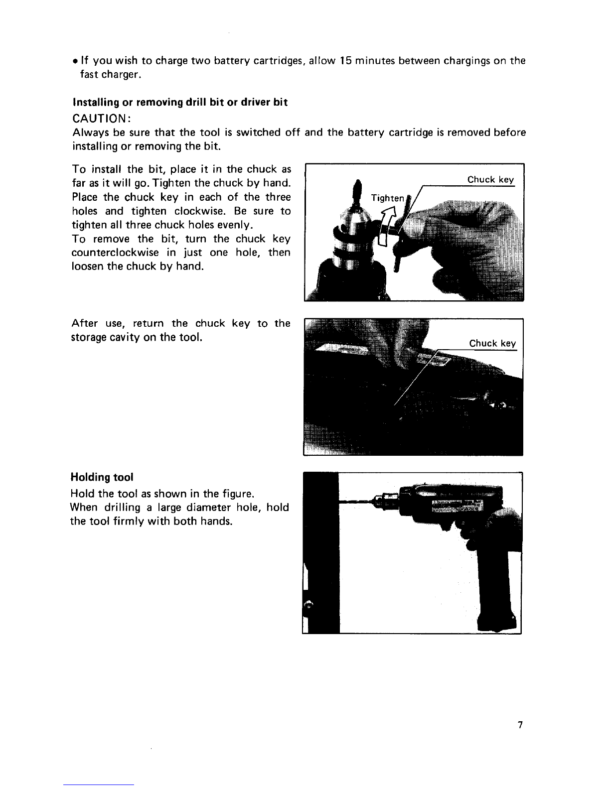
Installing or removing battery cartridge
*Always switch off the
tool
before insertion or removal
of
the battery cartridge.
.To
remove the battery cartridge, pull out
the set plate on the
tool
and grasp both
sides
of
the cartridge while withdrawing
it
from the barrel.
0
To
insert the battery cartridge, align the
tongue on the battery cartridge with the
groove in the housing and slip
it
into
place. Snap the set plate back into place.
Be sure
to
close the set plate fully before
using the
tool.
0
Do
not use force when inserting the battery cartridge.
If
the cartridge does not slide in easily,
it
is not being inserted correctly.
Charging
Plug the fast charger into your power
source. Insert the battery cartridge
so
that
the plus and minus terminals on the bat-
tery cartridge are on the same sides as their
respective markings on the fast charger.
Insert the cartridge fully into the port
so
that
it
rests on the charger port floor.
Press the start button (red). The charging
light will come on and charging will begin.
If the charging light does not come on,
press the reset button (yellow) first, then
the start button (red). If the charging light
goes out within
10
seconds even after pressing the reset button and start button a couple
of
times, the battery cartridge is dead. (CAUTION: Wait for more than
5
seconds after
the charging light goes out
to
press the reset button again.) Replace
it
with a new one.
When the charging light goes out after about one hour, you may remove the fully charged
battery cartridge.
After charging, unplug the charger from the power source.
CAUTION
:
0Your new battery cartridge is not charged. You will need
to
charge
it
before use.
.Do
not keep the button pressed in with tape,
etc.
or the circuit will not function pro-
perly. Also, a malfunction
of
the charger may result possibly causing overheating, etc.
0
If you try
to
charge a cartridge from a just-operated tool, sometimes the charging light
will not come on.
If
this occurs,
let
the cartridge
cool
off for a while. Then re-insert
it
and try
to
charge
it
once more.
6

0
If
you wish
to
charge two battery cartridges, allow
15
minutes between chargings on the
fast charger.
Installing or removingdrill bit or driver bit
CAUTION:
Always be sure that the
tool
is switched
off
and the battery cartridge is removed before
installing
or
removing the bit.
To install the bit, place
it
in the chuck as
far as
it
will go. Tighten the chuck by hand.
Place the chuck key
in
each
of
the three
holes and tighten clockwise. Be sure
to
tighten all three chuck holes evenly.
To
remove the bit, turn the chuck key
counterclockwise in just one hole, then
loosen the chuck by hand.
I
Chuck
key
Holding
tool
Hold the
tool
as shown in the figure.
When drilling a large diameter hole, hold
the
tool
firmly with both hands.
7

Switch action
Tool
speed is increased by increasing pres-
sure
on
the trigger.
To
start the tool,
simply pull the trigger. Release the trigger
to stop.
CAUTION
:
Before inserting the battery cartridge into the tool, always check
to
see
that
the trigger
switch actuates properly and returns to the
"OFF"
position when released.
Reversing switch action
This tool has a reversing switch to change
the direction of rotation. Slide the revers-
ing switch
to
the
right
for clockwise rota-
tion
or
to the left for counterclockwise.
Reversino
switch
1
CAUTION
:
0
Always check the direction of rotation before operation.
.Use the reversing switch only when the tool comes to
a
complete stop. Changing the
direction
of
rotation before the
tool
stops may
ruin
the tool.
Speed
change
To change the tool speed,
turn
the speed
change knob
so
that
the arrow
of
the de-
sired speed on the knob is aligned with the
0
-
400
R/min.
Speed
change
knob
refet-ence arrow
on
the
tool
body.
If
the
speed change knob does
not
turn
easily,
switch
on
the
tool
and
turn
the knob again
while the tool
is
running
under
no
load.
8

Adjusting fastening torque
I
I
The fastening torque can be adjusted in six
stages by turning the adjusting ring
so
that
the pointer on the adjusting ring points
to
a number on the
tool
body. The fastening
torque is minimum when thepointer points
to
the number
1
and maximum when
it
points
to
the
-8-
marking. The clutch
will
slip at varying torque levels when the
pointer is set at the numbers
1
to
5.
The
clutch is designed
not
to
slip atthe
st-
marking.
Before actual operation, drive a trial screw
into your material or a piece
of
duplicate
material
to
determine which torque level
is
required
for
a particular application.
Adjusting
ring
--7i
NOTE
:
The adjusting ring cannot be locked with the pointer positioned half-way between the
numbers.
Screwdriving operation
Place the point
of
the driver bit in the
screw head and apply pressure
to
the
tool.
Start the
tool
slowly and then increase the
speed gradually. Release the trigger as soon
as the clutch cuts in.
9

NOTE
:
0
Use the proper bit for the head
of
the screw that you wish
to
use.
0
Make sure that the driver bit is inserted straight in the screw head,
or
the screw and/or
bit may be damaged.
0
When driving wood screws, predrill Pilot
Nominal diameter
of
I
Recommended size
holes
to
make driving easier and
to
pre-
vent splitting
of
the workpiece. See the
chart.
wood screw
(mm)
3.1 (1/8")
3.5 (9/64")
3.8 (5/32")
4.5
(1
1
/64")
4.8 (3/16')
of
pilot hole
(mm)
2.0
-
2.2
(5/64"
-
3/32")
2.2
-
2.5
(3/32"
-
3/32")
2.5
-
2.8
(3/32"
-
7/64")
2.9
-
3.2
(7/64"
-
118")
3.1
-
3.4
(118''
-
9/64')
3.6
-
3.9
(9/64"
-
5/32")
5.5 (7/32")
Drilling
operation
0
Drilling in wood
When drilling in wood, best results are obtained with wood drills equipped with a guide
screw. The guide screw makes drilling easier by pulling the bit into the workpiece.
0
Drilling in metal
To
prevent the bit from slipping when starting a hole, make an indentation with a
centerpunch and hammer at the point
to
be drilled. Place the point
of
the bit in the
indentation and start drilling.
Use a cutting lubricant when drilling metals. The exceptions are iron and brass which
should be drilled dry.
CAUTION
:
0
Pressing excessively on the
tool
will not speed up the drilling. In fact, this excessive pres-
sure will only serve
to
damage the tip
of
your bit, decrease the
tool
performance and
shorten the service life of the
tool.
.There is a tremendous force exerted on the tool/bit at the time
of
hole breakthrough.
Hold the
tool
firmly and exert care when the bit begins
to
break through the workpiece.
0
A
stuck bit can be removed simply by setting the reversing switch
to
reverse rotation in
order
to
back out. However, the
tool
may back out abruptly
if
you do not hold
it
firmly.
*Always secure small workpieces in a vise or similar hold-down device.
10

Overload protector
The overload protector automatically cuts out to break the circuit whenever heavy work
is prolonged. Wait
20
-30
seconds before resuming operation.
Recycling
the
Battery
The
only
way
to
dispose
of
a
Makita battery
is
to
recycle it. The law prohibits any other
method
of
disposal.
Ni-Cd
To
recycle
a
battery:
1.
Remove the battery from the
tool.
2.
a).
Take the battery to
your
nearest Makita Factory
Service
Center
or
Distributorthat
has
been designated
as
a
Makita
battery recycling location.
Call your nearest Makita Service Centeror Distributor to determinethe
location that provides Makita batteryrecycling.Seeyour local Yellow Pages
under "Tools
-
Electric.
"
b). Take the battery
to
your
nearest
Makita Authorized
Service
Center
or
11

MAINTENANCE
CAUTION
:
Always be sure that the
tool
is switched off and the battery cartridge is removed before
attempting
to
perform inspection
or
maintenance.
To
maintain product SAFETY and RELlABl LITY, repairs, maintenance
or
adjustment
should
be
performed by Makita Authorized
or
Factory Service Centers, always using
Makita
replacement parts.
12

OPTIONAL ACCESSORIES
The accessorieslisted in this manual areavailableatan extra costfrom your Makita distributoror Makita factory
service center. Service centers are listed on
the
warranty card packed with your tool.
CAUTION
:
These accessories
or
attachments are recommended
for
use with your Makita tool specified in this
manual. The use
of
any other accessories
or
attachments might present a risk
of
injury to persons. The
accessories or attachments should be used only
in
the proper and intended manner.
Square
drill bit
0
Bits
784606-0A
Slotted
II
0
Fast charger
Model DC9700
Part
No.
113103-2
0
Charger 12V
for
car
Model DC9112
Part No. 1131
10-5
0
Rubber pad
assembly
Part
No.
123001-2
/r
G
d0
0
Chuck
key
S10
Part No.
763419-1
0
Wool
bonnet
Part
No.
743401
-6
NOTE:
The accessories listed
in
this manual are
available at an extra cost from your Makita
distributor
or
Makita factory service center.
Servicecenters are listed on the warranty
card packed with your tool.
0
Battery holster
Holster holds extra battery.
Part No. 823033-3C
0
Battery cover
Part No. 414938-7
0
Battery cartridge
9000
Part
No.
632007-4
0
Foam
polishing pad
Part
No.
743023-2
Plastic carrying case
Part
No.
824393-9
m
13

Dec
25-'86
EN
10
mm
(318")
CORDLESS DRIVER DRILL
Model
6093D
Note: The switch and other part configurations
may differ from country to country.
14

MODEL
6093D Dec -25-'86
EN
25
26
27
28
29
30
31
32
33
34
35
36
37
38
39
40
41
42
43
44
45
46
'i\M
DESCRIPTION
'i\M
$fD
DESCRIPTION
1
1
1
1
4
1
1
1
1
1
1
1
1
1
1
1
1
1
1
1
1
1
10
11
12
13
14
15
16
17
18
19
20
21
22
Pan
Head
Screw
M4x22 lWllh Washer]
Pan
Head
Screw
M4x35 IWtth Washer1
Housing
Set
(With Item 441
Guide Plate
cam Plate
Pan Head
Screw
M5x12
Change
Ring
Drill
Chuck
S10
Pan Head
Screw
M5x18
Spindle
Ball
Bearing 6000LLB
Stop
Ring
E-9
Compression Spring
10
Thin Washer
10
Spur
Gear
78
Ring
16
Spur
Gear
93
Thin Washer
10
Comprs.rlo" sprang
10
Flat
Washer
5
Plane
Bearing
5
DC
Motor
9
6
V
16
22
31
42
51
62
I1
81
91
1
1
1
1
1
1
1
1
1
1
1
1
1
Flat
Washer 14
Ball
Bearing
626LLB
Flat
Washer
6
Spur
Gear
89
Steel
Ball
4
8
Clutch Cam
Conical Compression
Spring
16-21
Pm
3
Ring
8
DlSC
Thrust Needle Gauge 1023
Flat
Washer
8
Slider
Gear
Complete 12-28
Plane
Bearing 4
P,"
3
Shifter
Holder
6
Hourmg
Set
lWith
Item
31
Switch
Name Plate
Leaf Spmg
23
5wNch
1
41
1
1
1
Set
Plate
24
1
1
Retaining
Ring
S-6
Note: The
switch
and other part Specifications may differ
from
country
to
country.
15

I
MAKITA
LIMED
ONE
YEAR
WARRANTY
Warranty
Policy
t
Every Makita tool is thoroughly inspected and tested before leaving the factory. It
is
warranted to
be free of defects from workmanship and materials for the period of
ONE YEAR
from the date of
original
purchase. Should any trouble develop during this one-year period, retum the
COMPLETE
tool, freight prepaid, to one of Makita’s Factory or Authorized ServiceCenters. If inspection shows
the trouble is caused by defective workmanship or material, Makita will repair (or at our option,
replace) without charge.
This
Warranty does not apply where:
repairs have been made or attempted by others:
repairs are required because
of
normal wear and tear:
The tool has been abused, misused or improperly maintained;
alterations have been made
to
the tool.
IN NO EVENT SHALL MAKITA BE LIABLE FOR ANY INDIRECT, INCIDENTAL OR CON-
SEQUENTIAL DAMAGES FROM THE SALE OR USE
OF
THE PRODUCT. THIS DISCLAIMER
APPLIES BOTH DURING AND AFTER THE TERM
OF
THIS WARRANTY.
MAKITA DISCLAIMS LIABILITY
FOR
ANY IMPLIED WARRANTIES, INCLUDING IMPLIED
WARRANTIES
OF
“MERCHANTABILITY” AND “FITNESS FOR A SPECIFIC PURPOSE,”
AFTER THE ONE-Y EAR TERM
OF
THIS WARRANTY.
This
Warranty gives
you
specific legal rights, and
you
may also have other rights which vary from
state to state. Some states do not allow the exclusion or Limitation of incidental or consequential
damages,
so
the above Limitation or exclusion may
limitation
on
how
long
an implied warranty lasts,
so
Makita Corporation
of
America
2650
Gainesville
Hwy.,
Buford,
GA
30518
MCA-4/93 883579D991
PRINTED
IN
USA.
1993-11-C
This manual suits for next models
1
Table of contents
Other Makita Drill manuals

Makita
Makita HP001G User manual

Makita
Makita 6305 User manual

Makita
Makita 8433D User manual

Makita
Makita DDF485 User manual

Makita
Makita HP2040 User manual

Makita
Makita 6501 User manual

Makita
Makita DHP484 User manual

Makita
Makita 6347DWDE User manual

Makita
Makita 6093DW User manual

Makita
Makita HP332D Manual

Makita
Makita HP1230 User manual

Makita
Makita DF330D User manual

Makita
Makita HP1630 User manual

Makita
Makita DBM131 User manual

Makita
Makita DDF480 User manual

Makita
Makita DA3010 User manual

Makita
Makita XPH07Z User manual

Makita
Makita BHP448 User manual

Makita
Makita maktec MT814 Manual

Makita
Makita M8100 User manual