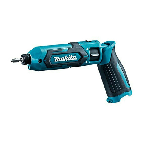
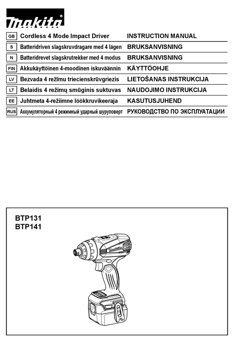
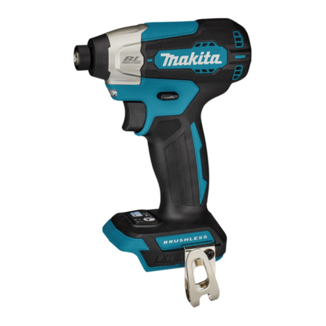
Makita TD001G User manual

TD001G
IMPORTANT: Read Before Using.
POMEMBNO: Pred uporabo preberite.
E RËNDËSISHME: Lexojeni përpara përdorimit.
ВАЖНО: Прочетете преди употреба.
VAŽNO: Pročitajte prije upotrebe.
ВАЖНО: Прочитајте пред употребата.
ВАЖНО: Прочитајте пре употребе.
IMPORTANT: Citiţi înainte de utilizare.
ВАЖЛИВО: Прочитайте перед використанням.
ВАЖНО! Прочтите перед использованием.
EN Cordless Impact Driver INSTRUCTION MANUAL 5
SL Akumulatorski udarni vijačnik NAVODILA ZA UPORABO 17
SQ Trapan me goditje me bateri MANUALI I PËRDORIMIT 28
BG
Акумулаторен ударен винтоверт
РЪКОВОДСТВО ЗА ЕКСПЛОАТАЦИЯ
40
HR Akumulatorski udarni zavrtač PRIRUČNIK S UPUTAMA 53
МК Безжичен ударен одвртувач УПАТСТВО ЗА УПОТРЕБА 65
SR Бежични ударни одвртач УПУТСТВО ЗА УПОТРЕБУ 77
RO Maşină de înşurubat cu
impact cu acumulator MANUAL DE INSTRUCŢIUNI 89
UK
Бездротовий ударний шуруповерт
ІНСТРУКЦІЯ З ЕКСПЛУАТАЦІЇ
101
RU Аккумуляторный ударный
шуруповерт
РУКОВОДСТВО ПО ЭКСПЛУАТАЦИИ
114

1
2
3
Fig.1
1
2
Fig.2
1
Fig.3
1
Fig.4
1
Fig.5
1
AB
Fig.6
3
12
Fig.7
1
Fig.8
2

Fig.9
Fig.10
12
Fig.11
Fig.12
3

1 2
Fig.13
1 32
Fig.14
3
2
1
Fig.15
Fig.16
4

5ENGLISH
ENGLISH (Original instructions)
SPECIFICATIONS
Model: TD001G
Fastening capacities Machine screw 4 mm - 8 mm
Standard bolt 5 mm - 16 mm
High tensile bolt 5 mm - 14 mm
No load speed (RPM) 4 (Max impact mode) 0 - 3,700 min-1
3 (Hard impact mode) 0 - 3,200 min-1
2 (Medium impact mode) 0 - 2,100 min-1
1 (Soft impact mode) 0 - 1,100 min-1
Wood mode 0 - 1,800 min-1
T mode (1) 0 - 2,400 min-1
T mode (2) 0 - 3,700 min-1
Bolt mode (1) 0 - 2,500 min-1
Bolt mode (2) 0 - 3,700 min-1
Bolt mode (3) 0 - 3,700 min-1
Impacts per minute 4 (Max impact mode) 0 - 4,400 min-1
3 (Hard impact mode) 0 - 3,600 min-1
2 (Medium impact mode) 0 - 2,600 min-1
1 (Soft impact mode) 0 - 1,100 min-1
Wood mode 0 - 4,400 min-1
T mode (1) -
T mode (2) 0 - 2,600 min-1
Bolt mode (1) -
Bolt mode (2) 0 - 4,400 min-1
Bolt mode (3) 0 - 4,400 min-1
Rated voltage D.C. 36 V - 40 V max
Overall length 120 mm
Net weight 1.7 - 2.0 kg
• Due to our continuing program of research and development, the specications herein are subject to change
without notice.
• Specications may dier from country to country.
• The weight may dier depending on the attachment(s), including the battery cartridge. The lightest and heavi-
est combination, according to EPTA-Procedure 01/2014, are shown in the table.
Applicable battery cartridge and charger
Battery cartridge BL4025 / BL4040
Charger DC40RA
• Some of the battery cartridges and chargers listed above may not be available depending on your region of
residence.
WARNING: Only use the battery cartridges and chargers listed above. Use of any other battery cartridges
and chargers may cause injury and/or re.
Intended use
The tool is intended for screw driving in wood, metal
and plastic.
Noise
The typical A-weighted noise level determined accord-
ing to EN62841-2-2:
Sound pressure level (LpA) : 96 dB(A)
Sound power level (LWA) : 107 dB (A)
Uncertainty (K) : 3 dB(A)

6ENGLISH
NOTE:
The declared noise emission value(s) has been
measured in accordance with a standard test method
and may be used for comparing one tool with another.
NOTE:
The declared noise emission value(s) may
also be used in a preliminary assessment of exposure.
WARNING: Wear ear protection.
WARNING:
The noise emission during actual
use of the power tool can dier from the declared val-
ue(s) depending on the ways in which the tool is used
especially what kind of workpiece is processed.
WARNING:
Be sure to identify safety measures
to protect the operator that are based on an estima-
tion of exposure in the actual conditions of use (tak-
ing account of all parts of the operating cycle such
as the times when the tool is switched o and when
it is running idle in addition to the trigger time).
Vibration
The vibration total value (tri-axial vector sum) deter-
mined according to EN62841-2-2:
Work mode: impact tightening of fasteners of the maxi-
mum capacity of the tool
Vibration emission (ah) : 10.0 m/s2
Uncertainty (K) : 1.5 m/s2
NOTE: The declared vibration total value(s) has been
measured in accordance with a standard test method
and may be used for comparing one tool with another.
NOTE: The declared vibration total value(s) may also
be used in a preliminary assessment of exposure.
WARNING:
The vibration emission during actual
use of the power tool can dier from the declared val-
ue(s) depending on the ways in which the tool is used
especially what kind of workpiece is processed.
WARNING:
Be sure to identify safety measures
to protect the operator that are based on an estima-
tion of exposure in the actual conditions of use (tak-
ing account of all parts of the operating cycle such
as the times when the tool is switched o and when it
is running idle in addition to the trigger time).
EC Declaration of Conformity
For European countries only
The EC declaration of conformity is included as Annex A
to this instruction manual.
SAFETY WARNINGS
General power tool safety warnings
WARNING: Read all safety warnings, instruc-
tions, illustrations and specications provided
with this power tool. Failure to follow all instructions
listed below may result in electric shock, re and/or
serious injury.
Save all warnings and instruc-
tions for future reference.
The term "power tool" in the warnings refers to your
mains-operated (corded) power tool or battery-operated
(cordless) power tool.
Cordless impact driver safety
warnings
1. Hold the power tool by insulated gripping
surfaces, when performing an operation
where the fastener may contact hidden wiring.
Fasteners contacting a "live" wire may make
exposed metal parts of the power tool "live" and
could give the operator an electric shock.
2. Always be sure you have a rm footing.
Be sure no one is below when using the tool in
high locations.
3. Hold the tool rmly.
4. Wear ear protectors.
5. Do not touch the bit or the workpiece immedi-
ately after operation. They may be extremely
hot and could burn your skin.
6. Keep hands away from rotating parts.
7. Use auxiliary handle(s), if supplied with the
tool. Loss of control can cause personal injury.
8. Hold the power tool by insulated gripping
surfaces, when performing an operation where
the cutting accessory may contact hidden
wiring. Cutting accessory contacting a "live"
wire may make exposed metal parts of the power
tool "live" and could give the operator an electric
shock.
SAVE THESE INSTRUCTIONS.
WARNING: DO NOT let comfort or familiarity
with product (gained from repeated use) replace
strict adherence to safety rules for the subject
product.
MISUSE or failure to follow the safety rules stated
in this instruction manual may cause serious
personal injury.
Important safety instructions for
battery cartridge
1. Before using battery cartridge, read all instruc-
tions and cautionary markings on (1) battery
charger, (2) battery, and (3) product using
battery.
2. Do not disassemble or tamper the battery
cartridge. It may result in a re, excessive heat,
or explosion.
3. If operating time has become excessively
shorter, stop operating immediately. It may
result in a risk of overheating, possible burns
and even an explosion.
4. If electrolyte gets into your eyes, rinse them
out with clear water and seek medical atten-
tion right away. It may result in loss of your
eyesight.

7ENGLISH
5. Do not short the battery cartridge:
(1) Do not touch the terminals with any con-
ductive material.
(2) Avoid storing battery cartridge in a con-
tainer with other metal objects such as
nails, coins, etc.
(3)
Do not expose battery cartridge to water or rain.
A battery short can cause a large current ow, over-
heating, possible burns and even a breakdown.
6. Do not store the tool and battery cartridge in
locations where the temperature may reach or
exceed 50 °C (122 °F).
7. Do not incinerate the battery cartridge even if
it is severely damaged or is completely worn
out. The battery cartridge can explode in a re.
8. Do not nail, cut, crush, throw, drop the battery
cartridge, or hit against a hard object to the
battery cartridge. Such conduct may result in a
re, excessive heat, or explosion.
9. Do not use a damaged battery.
10.
The contained lithium-ion batteries are subject to
the Dangerous Goods Legislation requirements.
For commercial transports e.g. by third parties,
forwarding agents, special requirement on pack-
aging and labeling must be observed.
For preparation of the item being shipped, consulting an
expert for hazardous material is required. Please also
observe possibly more detailed national regulations.
Tape or mask o open contacts and pack up the
battery in such a manner that it cannot move
around in the packaging.
11. When disposing the battery cartridge, remove
it from the tool and dispose of it in a safe
place. Follow your local regulations relating to
disposal of battery.
12. Use the batteries only with the products
specied by Makita. Installing the batteries to
non-compliant products may result in a re, exces-
sive heat, explosion, or leak of electrolyte.
13. If the tool is not used for a long period of time,
the battery must be removed from the tool.
14. During and after use, the battery cartridge may
take on heat which can cause burns or low
temperature burns. Pay attention to the han-
dling of hot battery cartridges.
15.
Do not touch the terminal of the tool immediately
after use as it may get hot enough to cause burns.
16. Do not allow chips, dust, or soil stuck into the
terminals, holes, and grooves of the battery
cartridge. It may result in poor performance or
breakdown of the tool or battery cartridge.
17. Unless the tool supports the use near a
high-voltage electrical power lines, do not use
the battery cartridge near a high-voltage elec-
trical power lines. It may result in a malfunction
or breakdown of the tool or battery cartridge.
SAVE THESE INSTRUCTIONS.
CAUTION: Only use genuine Makita batteries.
Use of non-genuine Makita batteries, or batteries that
have been altered, may result in the battery bursting
causing res, personal injury and damage. It will
also void the Makita warranty for the Makita tool and
charger.
Tips for maintaining maximum
battery life
1. Charge the battery cartridge before completely
discharged. Always stop tool operation and
charge the battery cartridge when you notice
less tool power.
2. Never recharge a fully charged battery car-
tridge. Overcharging shortens the battery
service life.
3. Charge the battery cartridge with room tem-
perature at 10 °C - 40 °C (50 °F - 104 °F). Let
a hot battery cartridge cool down before
charging it.
4. When not using the battery cartridge, remove
it from the tool or the charger.
5. Charge the battery cartridge if you do not use
it for a long period (more than six months).
FUNCTIONAL
DESCRIPTION
CAUTION: Always be sure that the tool is
switched o and the battery cartridge is removed
before adjusting or checking function on the tool.
Installing or removing battery
cartridge
CAUTION: Always switch o the tool before
installing or removing of the battery cartridge.
CAUTION: Hold the tool and the battery car-
tridge rmly when installing or removing battery
cartridge. Failure to hold the tool and the battery
cartridge rmly may cause them to slip o your hands
and result in damage to the tool and battery cartridge
and a personal injury.
► Fig.1: 1. Red indicator 2. Button 3. Battery cartridge
To remove the battery cartridge, slide it from the tool
while sliding the button on the front of the cartridge.
To install the battery cartridge, align the tongue on the
battery cartridge with the groove in the housing and slip
it into place. Insert it all the way until it locks in place
with a little click. If you can see the red indicator on the
upper side of the button, it is not locked completely.
CAUTION: Always install the battery cartridge
fully until the red indicator cannot be seen. If not,
it may accidentally fall out of the tool, causing injury to
you or someone around you.
CAUTION: Do not install the battery cartridge
forcibly. If the cartridge does not slide in easily, it is
not being inserted correctly.
8ENGLISH
Indicating the remaining battery
capacity
Press the check button on the battery cartridge to indi-
cate the remaining battery capacity. The indicator lamps
light up for a few seconds.
► Fig.2: 1. Indicator lamps 2. Check button
Indicator lamps Remaining
capacity
Lighted O Blinking
75% to 100%
50% to 75%
25% to 50%
0% to 25%
Charge the
battery.
The battery
may have
malfunctioned.
NOTE: Depending on the conditions of use and the
ambient temperature, the indication may dier slightly
from the actual capacity.
Tool / battery protection system
The tool is equipped with a tool/battery protection sys-
tem. This system automatically cuts o power to the
motor to extend tool and battery life. The tool will auto-
matically stop during operation if the tool or battery is
placed under one of the following conditions:
Overload protection
When the battery is operated in a manner that causes it
to draw an abnormally high current, the tool stops auto-
matically. In this situation, turn the tool o and stop the
application that caused the tool to become overloaded.
Then turn the tool on to restart.
Overheat protection
When the tool is overheated, the tool stops automati-
cally, and the front lamps blink. In this situation, let the
tool cool before turning the tool on again.
Overdischarge protection
When the battery capacity is not enough, the tool stops
automatically. In this case, remove the battery from the
tool and charge the battery.
Switch action
► Fig.3: 1. Switch trigger
CAUTION: Before installing the battery car-
tridge into the tool, always check to see that the
switch trigger actuates properly and returns to
the "OFF" position when released.
To start the tool, simply pull the switch trigger. Tool
speed is increased by increasing pressure on the switch
trigger. Release the switch trigger to stop.
NOTE: The tool automatically stops if you keep pull-
ing the switch trigger for about 6 minutes.
NOTE: While pulling the switch trigger, any other
buttons do not work.
Lighting up the front lamp
CAUTION: Do not look in the light or see the
source of light directly.
► Fig.4: 1. Front lamp
► Fig.5: 1. Button
Pull the switch trigger to turn on the front lamps. To turn o,
release the switch trigger. The front lamps go out approxi-
mately 10 seconds after releasing the switch trigger.
To turn o the front lamps within 10 seconds, press and
hold the button for a few seconds.
To disable the front lamps, turn o the lamp status. To
turn o the lamp status, rst pull and release the switch
trigger. Within 10 seconds after releasing the switch
trigger, press and hold the button for a few seconds.
When the lamp status is o, the front lamps will not turn
on even if the trigger is pulled.
To turn on the lamp status again, press and hold the
button for a few seconds.
NOTE:
When the tool is overheated, the front lamps
ash for one minute, and then the LED display goes o.
In this case, cool down the tool before operating again.
NOTE: To conrm the lamp status, pull the trigger.
When the front lamps light up by pulling the switch
trigger, the lamp status is on. When the front lamps
do not light up, the lamp status is o.
NOTE: Use a dry cloth to wipe the dirt o the lens of
the front lamps. Be careful not to scratch the lens of
front lamps, or it may lower the illumination.
Reversing switch action
► Fig.6: 1. Reversing switch lever
CAUTION: Always check the direction of
rotation before operation.
CAUTION: Use the reversing switch only after
the tool comes to a complete stop. Changing the
direction of rotation before the tool stops may dam-
age the tool.
CAUTION: When not operating the tool,
always set the reversing switch lever to the neu-
tral position.

9ENGLISH
This tool has a reversing switch to change the direction
of rotation. Depress the reversing switch lever from the
A side for clockwise rotation or from the B side for coun-
terclockwise rotation.
When the reversing switch lever is in the neutral posi-
tion, the switch trigger cannot be pulled.
Changing the application mode
What's the application mode?
The application mode is the variation of the driving
rotation and impact which are already preset in the tool.
By choosing a suitable application mode depending on
the work, you can accomplish quicker work and/or more
beautiful nish.
This tool features following application modes:
Impact force
• 4 (Max)
• 3 (Hard)
• 2 (Medium)
• 1 (Soft)
Assist type
• Wood mode
• T mode (1)
• T mode (2)
• Bolt mode (1) (clockwise/counterclockwise)
• Bolt mode (2) (clockwise/counterclockwise)
• Bolt mode (3) (clockwise/counterclockwise)
The application mode can be changed by the but-
ton , , or the quick mode-switching button.
► Fig.7: 1. Quick mode-switching button
2. Button 3. Button
By registering a certain application mode to the tool,
you can switch to the registered application mode by
just pressing the quick mode-switching button (quick
mode-switching function).
NOTE: When none of the lamp on the panel is lit,
pull the switch trigger once before pressing the quick
mode-switching button.
NOTE: You will not be able to change the application
mode if you do not operate the tool for approximately
one minute. In this case, pull the switch trigger
once and press the button, button, or quick
mode-switching button.
NOTE: Refer to "Registering the application mode"
in "Quick mode-switching function" section for how to
register the application mode.
Quick mode-switching button
The function of the quick mode-switching button varies
depending on whether you have registered the applica-
tion mode to the tool.
► Fig.8: 1. Quick mode-switching button
When the application mode is not
registered:
The level of impact force changes every time you press
the quick mode-switching button. The front lamps on
both sides will ash once when the impact force is
changed by pressing the quick mode-switching button.
When the application mode is registered:
The tool switches between the registered application
mode and current application mode every time you
press the quick mode-switching button. The front lamps
on both sides will ash once when the application
mode is changed by pressing the quick mode-switching
button.
NOTE: When the lamp status is o, the front lamps
will not ash even when the application mode is
changed by pressing the quick mode-switching
button.
NOTE: Refer to "Registering the application mode"
in "Quick mode-switching function" section for how to
register the application mode.
Disabling the quick mode-switching
button
You can also disable the quick mode-switching button.
After disabling, the quick mode-switching button will not
work for changing the impact force and switching the
application mode.
To disable the quick mode-switching button, press and
hold the quick mode-switching button and the but-
ton at the same time until the all lamps on the panel
blink.
To resume the quick mode-switching button, perform
the same procedure as above again.
NOTE: Registering and erasing the application mode
can be performed even if the quick mode-switching
button is disabled. After registering or erasing the
application mode, the quick mode-switching button
will be activated.

10 ENGLISH
Quick reference
The following table shows the functions of the quick mode-switching button.
indicates the quick mode-switching button.
Button(s) / Purpose Action How to conrm
(When quick mode-switching function
is OFF)
Changing the impact force by the quick
mode-switching button
Press
The front lamps on the tool ash once.
(When quick mode-switching function
is ON)
Switching to the registered application
mode
Press
The front lamps on the tool ash once.
+
Registering the application mode
Press and hold (each button) Example: Wood mode is registered
The lamp of desired application mode
blinks.
+
Erasing the registered application mode
Press and hold (each button)
All impact force grade lamps blink.
+
Disabling/resuming the quick
mode-switching button
Press and hold (each button)
All lamps on the panel blink.
: The lamp is blinking.
Changing the impact force
You can change the impact force in four steps: 4 (max), 3 (hard), 2 (medium), and 1 (soft).
This allows a tightening suitable to the work.
The level of impact force changes every time you press the button or the quick mode-switching button.
You can change the impact force within approximately one minute after releasing the switch trigger.
NOTE: You can extend the time to change the impact force approximately one minute if you press the but-
ton , , or the quick mode-switching button.
► Fig.9
Application mode
(Impact force grade
displayed on panel)
Maximum blows Purpose Example of application
4 (Max) 4,400 min-1 (/min) Tightening with the maximum force
and speed.
Driving screws to underwork materi-
als, tightening long screws or bolts.
3 (Hard) 3,600 min-1 (/min) Tightening with less force and speed
than Max mode (easier to control than
Max mode).
Driving screws to underwork materi-
als, tightening bolts.

11 ENGLISH
Application mode
(Impact force grade
displayed on panel)
Maximum blows Purpose Example of application
2 (Medium) 2,600 min-1 (/min) Tightening when a good nishing is
needed.
Driving screws to nishing boards or
plaster boards.
1 (Soft) 1,100 min-1 (/min) Tightening with less force to avoid
screw thread breakage.
Tightening sash screws or small
screws such as M6.
: The lamp is on.
NOTE: When none of the lamp on the panel is lit, pull the switch trigger once before pressing the button or the
quick mode-switching button.
NOTE: All lamps on the switch panel go out when the tool is turned o to save the battery power. The impact force
grade can be checked by pulling the switch trigger to the extent that the tool does not operate.
Changing assist type
This tool employs assist function that oers several easy-to-use application modes for driving screws with good
control.
The type of the application mode changes every time you press the button .
You can change the assist type within approximately one minute after releasing the switch trigger.
NOTE: You can extend the time to change the assist type approximately one minute if you press the button , ,
or the quick mode-switching button.
► Fig.10
Application mode
(Assist type displayed
on panel)
Maximum blows Feature Purpose
Wood mode * 4,400 min-1 (/min) This mode helps to prevent a screw from falling at
the beginning of driving. The tool drives a screw
with low-speed rotation at rst. After the tool starts
to impact, the rotation speed increases and reaches
the maximum speed.
Tightening long screws.
T mode (1) * –
(The tool stops rotating
soon after impact starts.)
This mode helps to prevent the screws from
over-tightening. It also accomplishes quick oper-
ation and good nish at the same time. The tool
drives a screw with high-speed rotation and stops
soon after the tool starts to impact.
NOTE:
The timing to stop the driving varies depending
on the type of the screw and material to be
driven. Make a test driving before using this
mode.
Driving self-drilling
screws to a thin metal
plate with good nish.
T mode (2) * 2,600 min-1 (/min) This mode helps to prevent the screws from
breakage and stripping. It also accomplishes quick
operation and good nish at the same time. The tool
drives a screw with high-speed rotation and slows
down the rotation when the tool starts to impact.
NOTE:
Release the switch trigger as soon as the tight-
ening nished to avoid overtightening.
Driving self-drilling
screws to a thick metal
plate with good nish.

12 ENGLISH
Application mode
(Assist type displayed
on panel)
Maximum blows Feature Purpose
Bolt mode –Clockwise
This mode helps to repeat screwdriving continu-
ously with equal torque. The stroke of the switch
trigger to reach maximum speed will become short
in this mode.
Counterclockwise
This mode helps to prevent a bolt from falling o.
When loosening a bolt with the tool driving in coun-
terclockwise rotation, the tool automatically stops or
slows down after the bolt/nut gets enough loosened.
The stroke of the switch trigger to reach maximum
speed will become short in this mode.
NOTE:
The timing to stop the driving varies depending
on the type of the screw and material to be
driven. Make a test driving before using this
mode.
Clockwise
Preventing over tighten-
ing of bolts.
Counterclockwise
Loosening bolts.
Bolt mode (1) –Clockwise
The tool stops automatically as soon as it has
started impact blows.
Counterclockwise
The impact force is 2. The tool stops automatically
as soon as it has stopped impacting.
–
Bolt mode (2) –Clockwise
The tool stops automatically approximately 0.3 sec-
ond later from the moment that the tool has started
impact blows.
Counterclockwise
The impact force is 4. The tool stops automatically
as soon as it has stopped impacting.
–
Bolt mode (3) –Clockwise
The tool stops automatically approximately 1 sec-
ond later from the moment that the tool has started
impact blows.
Counterclockwise
The tool slows down the rotation after it has stopped
impacting.
–
: The lamp is on.
* When the tool rotates counterclockwise, it rotates same as the 4 (max) mode, 4,400 min-1 (/min).
NOTE: When none of the lamp on the panel is lit, pull the switch trigger once before pressing the button .
NOTE: All lamps on the switch panel go out when the tool is turned o to save the battery power. The type of the
application mode can be checked by pulling the switch trigger to the extent that the tool does not operate.
Quick mode-switching function
What you can do with the quick mode-switching function
The quick mode-switching function saves the time for changing the application mode of the tool. You can switch to
your desired application mode by just pressing the quick mode-switching button. It is helpful when doing a repetitive
work which requires to switch between two application modes alternately.
EXAMPLE If you have a work to use T mode and max impact force, register the max impact force for quick
mode-switching function. Once register it, you can switch to the max impact force from T mode by just one click
of the quick mode-switching button. Also, you can return to T mode by pressing the quick mode-switching button
again.
Even if the tool is in other application mode than T mode, pressing the quick mode-switching button changes to
max impact force. It is convenient for you to register a application mode that you frequently use.
You can choose one of following application modes for quick mode-switching function:
Impact force
• 4 (Max)
• 3 (Hard)
• 2 (Medium)
• 1 (Soft)

13 ENGLISH
Assist type
• Wood mode
• T mode (1)
• T mode (2)
• Bolt mode (1) (clockwise/counterclockwise)
• Bolt mode (2) (clockwise/counterclockwise)
• Bolt mode (3) (clockwise/counterclockwise)
Registering application mode
To use the quick mode-switching function, register your desired application mode to the tool beforehand.
1. With the button or , choose your desired application mode.
2.
Press and hold the button and the quick mode-switching button at the same time until the lamp of desired application mode blinks.
► Fig.11: 1. Quick mode-switching button 2. Button
NOTE: You can overwrite the current application mode with new one by performing the procedure above.
Using the quick mode-switching function
When the tool is in the mode that is not registered, press the quick mode-switching button to switch to the registered appli-
cation mode. The tool switches between the registered application mode and last application mode every time you press the
quick mode-switching button. The front lamps on both sides will ash once when switching to the registered application mode.
The lamp of the registered application mode will blink when using the registered application mode.
Erasing the quick mode-switching function
Press and hold the button and button at the same time until all impact force grade lamps blink.
NOTE: After erasing the quick mode-switching function, the quick mode-switching button works for changing the
impact force.
Indication patterns
Application mode While registering the application mode When the registered application mode
turns on
4 (Max)
3 (Hard)
2 (Medium)
1 (Soft)
Wood mode
T mode (1)
T mode (2)
Bolt mode (1)

14 ENGLISH
Application mode While registering the application mode When the registered application mode
turns on
Bolt mode (2)
Bolt mode (3)
: The lamp is on.
: The lamp is blinking.
ASSEMBLY
CAUTION: Always be sure that the tool is
switched o and the battery cartridge is removed
before carrying out any work on the tool.
Installing or removing driver bit/
socket bit
► Fig.12
Use only driver bit/socket bit that has inserting portion
shown in the gure. Do not use any other driver bit/
socket bit.
For tool with shallow driver bit hole
A=12mm
B=9mm
Use only these type of driver
bit. Follow the procedure
1. (Note) Bit-piece is not
necessary.
For tool with deep driver bit hole
A=17mm
B=14mm
To install these types of driver
bits, follow the procedure 1.
A=12mm
B=9mm
To install these types of driver
bits, follow the procedure 2.
(Note) Bit-piece is necessary
for installing the bit.
Procedure 1
For tool without one-touch type sleeve
► Fig.13: 1. Driver bit 2. Sleeve
To install the driver bit, pull the sleeve in the direction of
the arrow and insert the driver bit into the sleeve as far
as it will go.
Then release the sleeve to secure the driver bit.
For tool with one-touch type sleeve
To install the driver bit, insert the driver bit into the
sleeve as far as it will go.
Procedure 2
In addition to Procedure 1, insert the bit-piece into the
sleeve with its pointed end facing in.
► Fig.14: 1. Driver bit 2. Bit-piece 3. Sleeve
To remove the driver bit, pull the sleeve in the direction
of the arrow and pull the driver bit out.
NOTE: If the driver bit is not inserted deep enough
into the sleeve, the sleeve will not return to its original
position and the driver bit will not be secured. In this
case, try re-inserting the bit according to the instruc-
tions above.
NOTE: When it is dicult to insert the driver bit, pull
the sleeve and insert it into the sleeve as far as it will
go.
NOTE: After inserting the driver bit, make sure that it
is rmly secured. If it comes out, do not use it.
Installing hook
CAUTION: When installing the hook, always
secure it with the screw rmly. If not, the hook
may come o from the tool and result in the personal
injury.
► Fig.15: 1. Groove 2. Hook 3. Screw
The hook is convenient for temporarily hanging the tool.
This can be installed on either side of the tool. To install
the hook, insert it into a groove in the tool housing on
either side and then secure it with a screw. To remove,
loosen the screw and then take it out.

15 ENGLISH
OPERATION
► Fig.16
The proper fastening torque may dier depending upon
the kind or size of the screw/bolt, the material of the
workpiece to be fastened, etc. The relation between fas-
tening torque and fastening time is shown in the gures.
Proper fastening torque for standard bolt
N•m
(kgf•cm)
M14
M12
M10
M8
M16
M14
M12
M10
M8
M16
140
(1428)
(1224)
(1020)
(816)
(612)
(408)
(204)
120
100
80
60
40
20
01
2
1
2
1. Fastening time (second) 2. Fastening torque
Proper fastening torque for high tensile bolt
200
180
160
140
120
100
80
60
40
20
N•m
(kgf•cm)
(2040)
(1836)
(1632)
(1428)
(1224)
(1020)
(816)
(612)
(408)
(204)
012
2
1
M14
M12
M14
M12
M10
M8
M10
M8
1. Fastening time (second) 2. Fastening torque
Hold the tool rmly and place the point of the driver bit
in the screw head. Apply forward pressure to the tool to
the extent that the bit will not slip o the screw and turn
the tool on to start operation.
NOTICE: If you use a spare battery to continue
the operation, rest the tool at least 15 min.
NOTE: Use the proper bit for the head of the screw/
bolt that you wish to use.
NOTE: When fastening M8 or smaller screw, choose
a proper impact force and carefully adjust pressure on
the switch trigger so that the screw is not damaged.
NOTE: Hold the tool pointed straight at the screw.
NOTE: If the impact force is too strong or you tighten
the screw for a time longer than shown in the gures,
the screw or the point of the driver bit may be over-
stressed, stripped, damaged, etc. Before starting your
job, always perform a test operation to determine the
proper fastening time for your screw.
The fastening torque is aected by a wide variety of
factors including the following. After fastening, always
check the torque with a torque wrench.
1. When the battery cartridge is discharged almost
completely, voltage will drop and the fastening
torque will be reduced.
2. Driver bit or socket bit
Failure to use the correct size driver bit or socket
bit will cause a reduction in the fastening torque.
3. Bolt
• Even though the torque coecient and the
class of bolt are the same, the proper fasten-
ing torque will dier according to the diame-
ter of bolt.
• Even though the diameters of bolts are the
same, the proper fastening torque will dier
according to the torque coecient, the class
of bolt and the bolt length.
4. The manner of holding the tool or the material
of driving position to be fastened will aect the
torque.
5. Operating the tool at low speed will cause a reduc-
tion in the fastening torque.
MAINTENANCE
CAUTION: Always be sure that the tool is
switched o and the battery cartridge is removed
before attempting to perform inspection or
maintenance.
NOTICE: Never use gasoline, benzine, thinner,
alcohol or the like. Discoloration, deformation or
cracks may result.
To maintain product SAFETY and RELIABILITY,
repairs, any other maintenance or adjustment should
be performed by Makita Authorized or Factory Service
Centers, always using Makita replacement parts.

16 ENGLISH
OPTIONAL
ACCESSORIES
CAUTION: These accessories or attachments
are recommended for use with your Makita tool
specied in this manual. The use of any other
accessories or attachments might present a risk of
injury to persons. Only use accessory or attachment
for its stated purpose.
If you need any assistance for more details regard-
ing these accessories, ask your local Makita Service
Center.
• Driver bits
• Socket bits
• Hook
• Tool hanger
• Plastic carrying case
• Makita genuine battery and charger
NOTE: Some items in the list may be included in the
tool package as standard accessories. They may
dier from country to country.

17 SLOVENŠČINA
SLOVENŠČINA (Originalna navodila)
TEHNIČNI PODATKI
Model: TD001G
Zatezne zmogljivosti Strojni vijak 4 mm–8 mm
Standardni vijak 5 mm–16 mm
Visoko natezni vijak 5 mm–14 mm
Hitrost brez obremenitve (vrt/min)
4 (način z največjim udarcem) 0–3.700 min-1
3 (način z močnim udarcem) 0–3.200 min-1
2 (način s srednjim udarcem) 0–2.100 min-1
1 (način z mehkim udarcem) 0–1.100 min-1
Način za les 0–1.800 min-1
Način T (1) 0–2.400 min-1
Način T (2) 0–3.700 min-1
Vijačni način (1) 0–2.500 min-1
Vijačni način (2) 0–3.700 min-1
Vijačni način (3) 0–3.700 min-1
Udarci na minuto 4 (način z največjim udarcem) 0–4.400 min-1
3 (način z močnim udarcem) 0–3.600 min-1
2 (način s srednjim udarcem) 0–2.600 min-1
1 (način z mehkim udarcem) 0–1.100 min-1
Način za les 0–4.400 min-1
Način T (1) -
Način T (2) 0–2.600 min-1
Vijačni način (1) -
Vijačni način (2) 0–4.400 min-1
Vijačni način (3) 0–4.400 min-1
Nazivna napetost D.C. 36 V–40 V najv.
Celotna dolžina 120 mm
Neto teža 1,7–2,0 kg
• Ker nenehno opravljamo raziskave in razvijamo svoje izdelke, se lahko tehnični podatki v tem dokumentu
spremenijo brez obvestila.
• Tehnični podatki se lahko razlikujejo od države do države.
• Teža se lahko razlikuje glede na priključke, vključno z akumulatorsko baterijo. Najlažja in najtežja kombinacija v
skladu s postopkom EPTA 01/2014 sta prikazani v preglednici.
Uporabna akumulatorska baterija in polnilnik
Baterijski vložek BL4025/BL4040
Polnilnik DC40RA
• Nekatere zgoraj navedene akumulatorske baterije in polnilniki morda v vaši državi prebivališča niso na voljo.
OPOZORILO: Uporabljajte le zgoraj navedene akumulatorske baterije in polnilnike. Uporaba drugih
akumulatorskih baterij in polnilnikov lahko povzroči telesne poškodbe in/ali požar.
Predvidena uporaba
Orodje je namenjeno za vijačenje v les, kovino in
plastiko.
Hrup
Običajna A-ovrednotena raven hrupa v skladu z
EN62841-2-2:
Raven zvočnega tlaka (LpA): 96 dB (A)
Raven zvočne moči (LWA): 107 dB (A)
Odstopanje (K): 3 dB (A)

18 SLOVENŠČINA
OPOMBA: Navedene vrednosti oddajanja hrupa so
bile izmerjene v skladu s standardnimi metodami
testiranja in se lahko uporabljajo za primerjavo orodij.
OPOMBA: Navedene vrednosti oddajanja hrupa
se lahko uporabljajo tudi pri predhodni oceni
izpostavljenosti.
OPOZORILO: Uporabljajte zaščito za sluh.
OPOZORILO: Oddajanje hrupa med dejansko
uporabo električnega orodja se lahko razlikuje od
navedenih vrednosti, odvisno od načina uporabe
orodja in predvsem vrste obdelovanca.
OPOZORILO: Upravljavec mora za lastno
zaščito poznati varnostne ukrepe, ki temeljijo
na oceni izpostavljenosti v dejanskih pogojih
uporabe (poleg časa proženja je treba upoštevati
celoten delovni cikel, vključno s časom, ko je
orodje izklopljeno, in časom, ko deluje v prostem
teku).
Vibracije
Skupne vrednosti vibracij (vektorska vsota treh osi) v
skladu z EN62841-2-2:
Delovni način: udarno privijanje pritrjevalnikov z najve-
čjo zmogljivostjo orodja
Emisije vibracij (ah): 10,0 m/s2
Odstopanje (K): 1,5 m/s2
OPOMBA: Navedene skupne vrednosti oddajanja
vibracij so bile izmerjene v skladu s standardnimi
metodami testiranja in se lahko uporabljajo za primer-
javo orodij.
OPOMBA: Navedene skupne vrednosti oddajanja
vibracij se lahko uporabljajo tudi pri predhodni oceni
izpostavljenosti.
OPOZORILO: Oddajanje vibracij med
dejansko uporabo električnega orodja se lahko
razlikuje od navedenih vrednosti, odvisno
od načina uporabe orodja in predvsem vrste
obdelovanca.
OPOZORILO: Upravljavec mora za lastno
zaščito poznati varnostne ukrepe, ki temeljijo
na oceni izpostavljenosti v dejanskih pogojih
uporabe (poleg časa proženja je treba upoštevati
celoten delovni cikel, vključno s časom, ko je
orodje izklopljeno, in časom, ko deluje v prostem
teku).
Izjava o skladnosti ES
Samo za evropske države
Izjava ES o skladnosti je vključena v dodatku A, ki je
priložen tem navodilom za uporabo.
VARNOSTNA
OPOZORILA
Splošna varnostna opozorila za
električno orodje
OPOZORILO: Preberite vsa varnostna opo-
zorila in navodila s slikami in tehničnimi podatki,
ki so dobavljeni skupaj z električnim orodjem.
Ob neupoštevanju spodaj navedenih navodil obstaja
nevarnost električnega udara, požara in/ali hudih
telesnih poškodb.
Shranite vsa opozorila in navo-
dila za poznejšo uporabo.
Izraz „električno orodje“ v opozorilih se nanaša na vaše
električno orodje (s kablom) ali baterijsko električno
orodje (brez kabla).
Varnostna opozorila za brezžični
udarni vijačnik
1. Če obstaja nevarnost, da bi s pritrjevalnikom
prerezali skrito električno napeljavo, držite ele-
ktrično orodje na izoliranih držalnih površinah.
Ob stiku z vodniki pod napetostjo dobijo napetost
vsi neizolirani kovinski deli električnega orodja,
zaradi česar lahko pride do električnega udara.
2. Vedno zagotovite, da imate trden oprijem na
podlagi, kjer stojite.
Kadar uporabljate orodje na višini, se prepri-
čajte, da spodaj ni nikogar.
3. Trdno držite orodje.
4. Uporabljajte zaščito za sluh.
5. Takoj po končani obdelavi se ne dotikajte
nastavka ali obdelovanca. Lahko sta zelo
vroča in povzročita opekline kože.
6. Ne približujte rok vrtečim se delom.
7. Uporabite pomožne ročaje, če so dobavljeni
z orodjem. Izguba nadzora lahko povzroči
poškodbe oseb.
8. Če obstaja nevarnost, da bi z rezilnim orodjem
prerezali skrito električno napeljavo, držite ele-
ktrično orodje na izoliranih držalnih površinah.
Ob stiku z vodniki pod napetostjo dobijo napetost
vsi neizolirani kovinski deli električnega orodja,
zaradi česar lahko uporabnik utrpi električni udar.
SHRANITE TA NAVODILA.
OPOZORILO: NE dovolite, da bi zaradi udob-
nejšega dela ali znanja o uporabi izdelka (prido-
bljenega z večkratno uporabo) opustili strogo
upoštevanje varnostnih zahtev v okviru pravilne
uporabe orodja.
ZLORABA ali neupoštevanje varnostnih zahtev
v teh navodilih za uporabo lahko povzroči resne
telesne poškodbe.

19 SLOVENŠČINA
Pomembna varnostna navodila za
akumulatorsko baterijo
1. Pred uporabo baterijskega vložka preberite
vsa navodila in opozorilne oznake na (1) pol-
nilniku akumulatorja, (2) akumulatorju in (3)
izdelku, ki uporablja akumulator.
2. Ne razstavljajte ali spreminjajte akumulatorske
baterije. S tem lahko povzročite požar, preko-
merno vročino ali eksplozijo.
3. Če se je čas delovanja občutno skrajšal, takoj
prenehajte uporabljati orodje. V nasprotnem
primeru lahko pride do pregretja, morebitnih
opeklin in celo eksplozije.
4. Če pride elektrolit v stik z očmi, jih sperite s
čisto vodo in takoj poiščite zdravniško pomoč.
Posledica je lahko izguba vida.
5. Ne povzročite kratkega stika baterijskega
vložka:
(1) Ne dotikajte se priključkov s kakršnim
koli prevodnim materialom.
(2) Izogibajte se shranjevanju baterijskega
vložka v vsebniku z drugimi kovinskimi
predmeti kot so žeblji, kovanci itn.
(3) Ne izpostavljajte baterijskega vložka vodi
ali dežju.
Kratek stik akumulatorja lahko povzroči velik
električni tok, pregrevanje, morebitne opekline
in celo okvaro.
6. Ne shranjujte orodja in baterijskega vložka
na mestih, kjer lahko temperatura doseže ali
preseže 50 °C.
7. Ne sežigajte baterijskega vložka, tudi če je
hudo poškodovan ali v celoti izpraznjen.
Baterijski vložek lahko v ognju eksplodira.
8. Ne pribijajte, režite, drobite, mečite, spuščajte
akumulatorske baterije oziroma ne udarjajte
z akumulatorsko baterijo po trdem predmetu.
Takšno ravnanje lahko povzroči požar, preko-
merno vročino ali eksplozijo.
9. Ne uporabljajte poškodovanih akumulatorjev.
10. Priložene litij-ionske baterije ustrezajo zahte-
vam zakonodaje v zvezi z nevarnim blagom.
Za komercialne prevoze, npr. tiste, ki jih opravljajo
tretje stranke in carinski posredniki, je treba upo-
števati posebne zahteve v zvezi z embalažo in
označevanjem.
Med postopkom priprave na odpremo izdelka se
je treba posvetovati s strokovnjakom za nevarne
snovi. Pri tem upoštevajte tudi podrobnejše nacio-
nalne predpise.
Odprte stike oblepite z lepilnim trakom ali jih dru-
gače zaščitite, baterijo pa zapakirajte tako, da se v
embalaži ne more premikati.
11. Ko odstranjujete akumulatorsko baterijo, jo
vzemite iz orodja in varno zavrzite. Upoštevajte
lokalne uredbe glede odlaganja baterije.
12. Baterije uporabljajte le z izdelki, ki jih določi
Makita. Če namestite baterije v neskladne izdelke,
lahko pride do požara, pregrevanja, eksplozije ali
puščanja elektrolita.
13. Če orodja dlje časa ne uporabljate, morate iz
njega odstraniti baterijo.
14. Med uporabo in po uporabi lahko akumu-
latorska baterija postane vroča in povzroči
opekline. Z vročimi akumulatorskimi baterijami
ravnajte pazljivo.
15. Ne dotikajte se priključka orodja takoj po upo-
rabi, ker se lahko dovolj segreje, da povzroči
opekline.
16. Ne dovolite, da bi se v priključke, odprtine in
utore akumulatorske baterije zlepili ostružki,
prah ali zemlja. Umazanija lahko povzroči slabše
delovanje ali okvaro orodja oziroma akumulator-
ske baterije.
17. Razen če orodje podpira uporabo v bližini
visokonapetostnih električnih vodov, akumula-
torske baterije ne uporabljajte v bližini visoko-
napetostnih električnih vodov. Takšna uporaba
lahko povzroči motnje v delovanju ali okvaro
orodja oziroma akumulatorske baterije.
SHRANITE TA NAVODILA.
POZOR: Uporabljajte le originalne baterije
Makita. Če uporabljate neoriginalne baterije Makita
ali baterije, ki so bile spremenjene, lahko pride do
eksplozije baterije in posledično do požara, telesnih
poškodb ali materialne škode. S takšno uporabo
boste tudi razveljavili garancijo Makita za orodje in
polnilnik Makita.
Nasveti za ohranjanje največje
zmogljivosti akumulatorja
1. Napolnite baterijski vložek, preden se v celoti
izprazni. Ko opazite, da ima orodje manjšo
moč, vedno ustavite delovanje orodja in napol-
nite baterijski vložek.
2. Nikoli znova ne polnite popolnoma napol-
njenega baterijskega vložka. Prenapolnjenje
skrajša življenjsko dobo akumulatorja.
3. Baterijski vložek s sobno temperaturo pol-
nite pri temperaturi okolja od 10 °C do 40 °C.
Počakajte, da se vroč baterijski vložek pred
polnjenjem ohladi.
4. Ko akumulatorske baterije ne uporabljate, jo
odstranite iz orodja ali polnilnika.
5. Če baterijskega vložka ne uporabljate dalj časa
(več kot 6 mesecev), ga napolnite.

20 SLOVENŠČINA
OPIS DELOVANJA
POZOR:
Pred nastavljanjem ali preizkusom
delovanja orodja se prepričajte, ali je orodje izklju-
čeno in ali je akumulatorska baterija odstranjena.
Nameščanje ali odstranjevanje
akumulatorske baterije
POZOR: Vedno izklopite orodje, preden name-
stite ali odstranite akumulatorsko baterijo.
POZOR:
Kadar nameščate ali odstranjujete akumula-
torsko baterijo, trdno držite orodje in akumulatorsko bate-
rijo. Če orodja in akumulatorske baterije ne držite trdno, se lahko
zgodi, da vam zdrsneta iz rok, posledica pa je lahko poškodba
orodja in akumulatorske baterije ter telesna poškodba.
► Sl.1: 1. Rdeči indikator 2. Gumb 3. Baterijski vložek
Če želite odstraniti akumulatorsko baterijo, jo potisnite iz
orodja, pri tem pa pomikajte gumb na sprednji strani vložka.
Akumulatorsko baterijo vstavite tako, da poravnate jeziček na
bateriji z utorom na ohišju in jo potisnete v ležišče. Potisnite jo
do konca, da se zaskoči. Če je rdeči indikator na zgornji strani
gumba viden, pomeni, da baterija ni ustrezno zaklenjena.
POZOR:
Vedno namestite akumulatorsko bate-
rijo tako, da rdeči indikator ni več viden. Če tega ne
upoštevate, lahko baterija nepričakovano pade iz orodja
in poškoduje vas ali osebe v neposredni bližini.
POZOR: Ne nameščajte akumulatorske bate-
rije s silo. Če se akumulatorska baterija ne zaskoči
zlahka, ni pravilno vstavljena.
Prikazuje preostalo raven
napolnjenosti akumulatorja
Pritisnite gumb za preverjanje na baterijskem vložku,
da preverite raven napolnjenosti akumulatorja.
Indikatorske lučke na kratko zasvetijo.
► Sl.2: 1. Indikatorske lučke 2. Gumb za preverjanje
Indikatorske lučke Prikaz pre-
ostale ravni
napolnjenosti
Sveti Ne sveti Utripa
od 75 % do
100 %
od 50 % do
75 %
od 25 % do
50 %
od 0 % do
25 %
Napolnite
akumulator.
Akumulator
je morda
okvarjen.
OPOMBA: Odvisno od pogojev uporabe in okoljske
temperature se označba lahko nekoliko razlikuje od
dejanske napolnjenosti.
Zaščitni sistem orodja/akumulatorja
Orodje je opremljeno z zaščitnim sistemom za orodje/
akumulator. Sistem samodejno prekine napajanje orodja,
da podaljša življenjsko dobo orodja in akumulatorja.
Orodje se samodejno zaustavi med delovanjem, če
orodje ali akumulator delujeta pod naslednjimi pogoji:
Zaščita pred preobremenitvijo
Kadar akumulator uporabljate na način, ki povzroča
uporabo neobičajno visokega toka, se orodje samo-
dejno ustavi. V tem primeru izklopite orodje in prekinite
delo, ki je povzročilo preobremenitev orodja. Nato vklo-
pite orodje, da ga znova zaženete.
Zaščita pred pregrevanjem
Če je orodje pregreto, se orodje samodejno ustavi in
sprednje lučke začnejo utripati. V tem primeru pustite,
da se orodje ohladi, preden ga znova vklopite.
Zaščita pred izpraznjenjem
Ko je zmogljivost akumulatorja prenizka, se orodje
samodejno ustavi. V tem primeru odstranite akumulator
iz orodja in ga napolnite.
Delovanje stikala
► Sl.3: 1. Sprožilno stikalo
POZOR: Preden vstavite akumulatorsko
baterijo v orodje, se vedno prepričajte, da stikalo
deluje brezhibno in se vrača v položaj za izklop
(OFF), ko ga spustite.
Za zagon orodja povlecite sprožilno stikalo. Hitrost
orodja se poveča za povečani tlak na sprožilnem sti-
kalu. Za izklop spustite stikalo.
OPOMBA: Orodje se samodejno ustavi, če držite
sprožilno stikalo pritisnjeno približno 6 minut.
OPOMBA: Drugi gumbi med pritiskanjem sprožilca
ne delujejo.
Vklop sprednje lučke
POZOR: Ne glejte neposredno v lučko ali vir
svetlobe.
► Sl.4: 1. Sprednja lučka
► Sl.5: 1. Gumb
Povlecite sprožilno stikalo za vklop sprednjih lučk. Za
izklop spustite sprožilec. Sprednje lučke ugasnejo prib-
ližno 10 sekund zatem, ko spustite sprožilec.
Če želite sprednjih lučke izklopiti v 10 sekundah, priti-
snite in nekaj sekund držite gumb .
Če želite onemogočiti sprednje lučke, izklopite stanje
lučke. Če želite stanje lučke izklopiti, najprej povlecite in
spustite sprožilec. V 10 sekundah po tem, ko ste spustili
sprožilec, pritisnite in nekaj sekund držite gumb .
Other manuals for TD001G
5
Table of contents
Languages:
Other Makita Impact Driver manuals

Makita
Makita 6905B User manual

Makita
Makita BTD120 User manual

Makita
Makita BTW120 User manual

Makita
Makita DTD157 User manual

Makita
Makita 6910 User manual

Makita
Makita 6916FD User manual

Makita
Makita DTL063Z User manual

Makita
Makita DTDA040 Series User manual

Makita
Makita 6932FD User manual

Makita
Makita TD127DZ User manual