Makita DUR142L Manual

PRODUCT
CONCEPT AND MAIN APPLICATIONS
Specification
Standard equipment
Optional accessories
P 1/ 13
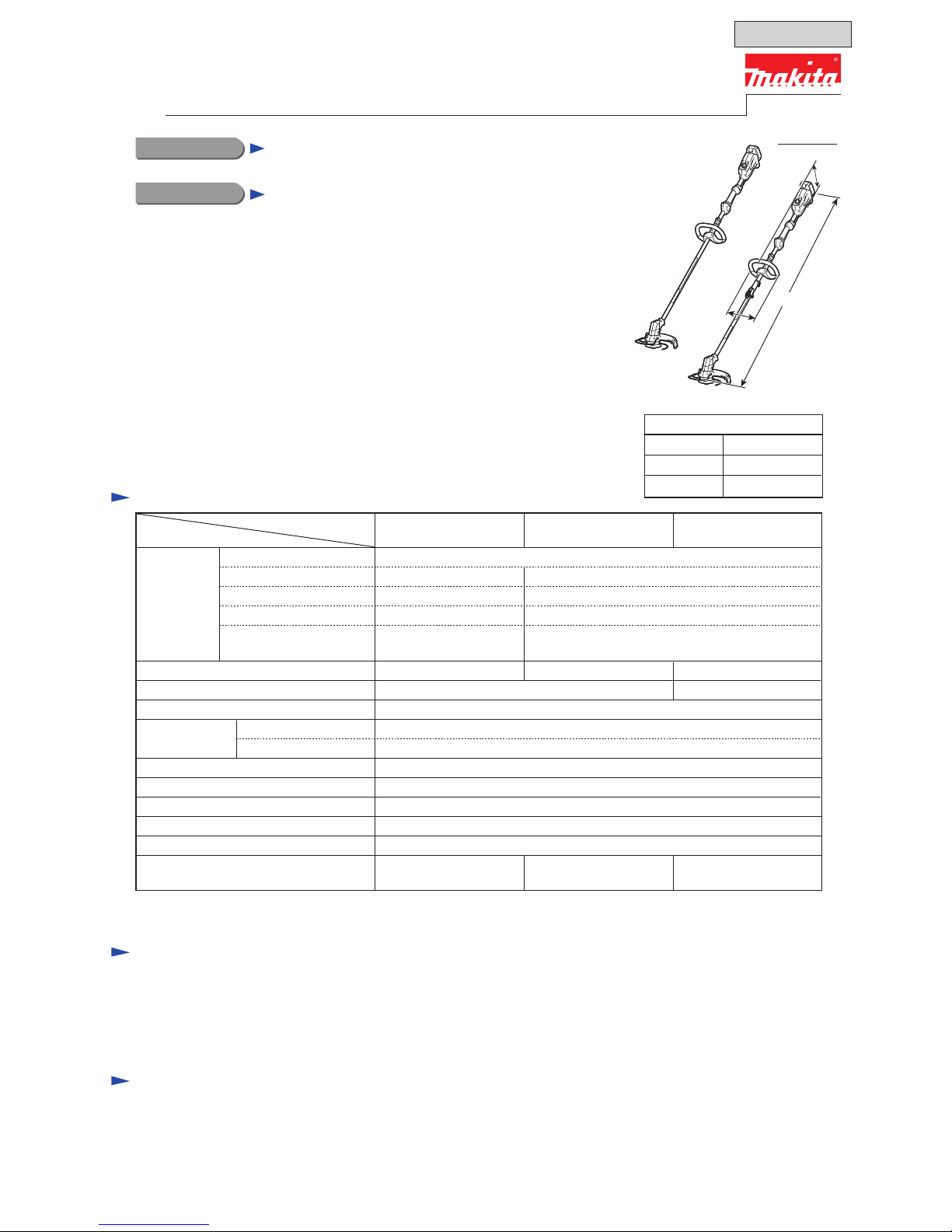
Models DUR142L/DUR182L and DUR183L are lightweight yet powerful
cordless grass trimmers, powered by 14.4/18V Li-ion batteries.
High power yet lightweight Brushless DC motor placed on the bottom side
of the shaft will provide easy handling and high trimming performance.
DUR142L and DUR182L are one-piece shaft models while DUR183L is
a split shaft model.
Their other main features are:
• Enhanced dust and drip-proof performance for use in bad weather
• Compatible with Metal blades, Nylon cutting heads and Plastic blade
• Reverse switch for removing grass clippings from the cutting tool
Dimensions: mm (")
Height (H)
Width (W)
1,843 (72-1/2)Length (L)
253 (10)
287 (11-1/4)
Single harness
Nylon cutting head
Hex wrench 4
Hex wrench 5
Safety goggles
Accessory bag
Cap 24 (for BUR183L only)
Note: The standard equipment may vary by country or model variation.
DUR142L/DUR182L
DUR183L
Cordless Grass Trimmer
Model No.
Description
Fast charger DC18RC
Charger DC18SD
Charger DC24SC
Four port multi charger DC18SF
Automotive charger DC18SE
Universal guard
Nylon cord ø2mm -15m
Metal blades*
(Triple blade, Star blade, Eddy blade)
Plastic blade (cutting width: 260mm)
For DUR142L
Battery BL1415N
Battery BL1415NA
Battery BL1430
Battery BL1430A
Battery BL1440
Battery BL1450
For DUR142L
Battery BL1815N
Battery BL1820
Battery BL1830
Battery BL1840
Battery BL1850
*1With Battery, Nylon cutting head, Harness, Protector, Handle
*2With BL1430, BL1440 or BL1450 *3With BL1830, BL1840 or BL1850
Cutting width:
mm (")
Nylon cutting head
Shaft type
Weight according to
EPTA-Procedure01/2003*1: kg (lbs)
No load speed: minˉ¹=rpm
300 (11-3/4)
Metal blade 230 (9)
200 250
Split shaftOne-piece shaft
Reverse switch Yes
Variable speed control Yes
Electric brake Yes
Spindle thread size M8x1.25, Left-handed
Over load protection Yes
250
3,500 - 6,000
4.1 (9.1)*3
3.9 (8.6)*33.8 (8.3)*2
Battery
Max. output: W
Charging time: min.
Capacity: Ah
Cell
Voltage: V 14.4 18
DUR183LDUR142L DUR182L
1.5, 2.0, 3.0, 4.0, 5.01.5, 3.0, 4.0, 5.0
Energy capacity: Wh 22, 44, 58, 72 27, 36, 54, 72, 90
Li-ion
15, 22, 36, 45
with DC18RC
15, 24, 22, 36, 45
with DC18RC
Model
Specification
Note: • These products are not compatible with BL1415/ BL1815.
• Use of metal blades in some countries is prohibited due to
their safety regulations.
DUR183L
DUR182L
L
W
H
*Only for countries without regulations
TECHNICAL INFORMATION
OFFICIAL USE
for ASC & Sales Shop

CAUTION: Repair the machine in accordance with “Instruction manual” or “Safety instructions”.
P 2/ 13
Apply Makita grease N. No.2 to the following portions designated with the black triangle to protect parts and product
from unusual abrasion.
[3] DISASSEMBLY/ASSEMBLY
[3] -1. Motor section
[1] NECESSARY REPAIRING TOOLS
Code No. Description Use for
1R022 Bearing plate (for Arbor press) supporting Helical gear 31 when removing the gear with 1R279
1R268 Spring pin extractor M3 locking Cutter shaft when removing Cutter assembly
1R279 Round bar for arbor 5-50 removing Helical gear 31
[2] LUBRICATION
Fig. 1
Item No. Description Amount
approx. 3 g
Portion to lubricate
DISASSEMBLING
69 Motor housing set Gear room where Helical gear 31 engages with Armature’s gear
(1) Remove the accessories and attachment from Motor housing as drawn in Fig. 2.
56
1R268Motor housing
1. While inserting 1R268 into the hole
of Motor housing set to stop Cutter
shaft revolving, turn Cutter assembly
clockwise by hand.
Cutter assembly is removed from
Cutter shaft.
2. Remove Guard and
Receive washer from
Cutter shaft.
3. Remove Wire guard by opening
the both ends. Then, unscrew
two M6x30 Hex socket head bolts
and Washers, then remove Protector
and Protector holder.
Cutter
assembly
Guard
Washer
(2 pcs.)
Receive washer
Insertion hole
for Spindle lock
Cutter assembly
Wire guard
Protector holder
Protector
M6x30
Hex socket
head bolt
(2 pcs.)
Fig. 2
56
69
Helical gear 31
Armature’s gear
Repair

[3] DISASSEMBLY/ASSEMBLY
[3]-1. Motor section (cont.)
DISASSEMBLING
(2) Disassemble Motor section as drawn in Fig. 3.
1. Remove Motor housing (R) by unscrewing eight 4x18
Tapping screws.
Fig. 3
Cutter shaft
Helical gear 31
Bearing box
Motor housing (R)
Motor housing (L)
Pipe complete
4x18 Tapping screw
(8 pcs.)
5. Pull out Cutter shaft from Bearing box by hand.
6. Hold Cutter shaft section by inserting 1R022 between
Ball bearing 6000DDW and Helical gear 31.
Helical gear 31
Cutter shaft Ball bearing 6000DDW
1R022 1R022
Repair
P 3/ 13
Stator
5-pin connector.Insulated connector
(3 pcs.)
3. Separate Pipe complete / Pipe A complete
from Motor housing set (L).
2. Disconnect 5-pin Connector and cut three Insulated
connectors to separate Power supply cord unit from
Stator section.
Pipe complete / Pipe A complete
Note: Refer to the next page for disassembly of
Pipe A complete for DUR183L.
4. Remove Rubber sleeve 24.
Pipe complete / Pipe A complete is replaced.
Rubber sleeve 24
Rotor
8. Rotor can be pulled off from Bearing box by hand.
Bearing box
<Note in Repairing>
This gear section is factory-
assembled to Rotor.
The Rotor has to be replaced
together with the gear.
7. Press Cutter shaft end with 1R279 to separate
Cutter shaft and Ball bearing 6000DDW from
Helical gear 31.
Helical gear 31
Ball bearing
626DDW
1R279
Cutter shaft
Ball bearing
6000DDW

ASSEMBLING
DISASSEMBLING
Repair
P 4/ 13
[3] DISASSEMBLY/ASSEMBLY
[3]-1. Motor section (cont.)
(1) Assemble Rotor and Cutter shaft section to Bearing box by reversing the disassembly procedure. (Refer to Fig. 3)
(2) Set Motor section to Motor housing (L) by reversing the disassembly procedure. (Refer to Fig. 3)
(3) Assemble Pipe complete / Pipe A complete to Motor housing (L) as drawn in Fig. 4.
Note: • Assemble Rubber sleeve 24 to Pipe complete/ Pipe A complete while fitting the inner projection of the sleeve to
the hole of the pipe.
• Fit the outer projection of Rubber sleeve 24 into the notch of Housing set and fit the inner projection into
Pipe complete / Pipe A complete.
• Face Stopper pin B of DUR183L to the lower side.
Refer to Fig. 5.
Stopper pin B in Pipe A complete (DUR183L only)
Fig. 5
Inner projection of
Rubber sleeve 24
Inner projection of
Housing set
Notch of Housing set
Oval hole Outer projection of
Rubber sleeve 24
Pipe complete / Pipe A complete
Rubber sleeve 24
(3) As for Split shaft model DUR183L, refer to Fig. 4.
Fig. 4
While pressing and unlocking the side stoppers of Power supply cord unit
from the side holes of Pipe A complete with thin slotted screwdrivers,
push the Power supply cord unit out of Pipe A complete.
Note: Be careful not to lose Stopper pin in this step.
Side stoppers of Power supply cord unit
Side holes of Pipe A complete
Stopper pin
Stopper pin
Power supply
cord unit

DISASSEMBLING
(1) Separate Pipe complete/ Pipe B from Housing set L as drawn in Fig. 6.
1. After removing Housing set R from Housing set L,
disconnect 5 pin connector and 3 pin connector.
Then, cut three Closed end splices at the points
designated with black dotted lines below.
2. Unscrew 4x18 Tapping screws.
Pipe complete and Power supply cord unit
are separated from Housing set.
3. Pipe B for DUR183L, do the following steps.
• Loosen M6x12 Hex socket head bolt and then remove Joint 24.
• Remove Power supply cord unit from Pipe B.
Closed end splice
5 pin
connector
3 pin
connector
Clamp 24
Pipe complete / Pipe B
Housing set L
4x18 Tapping screw
4x18 Tapping screw
M6x12 Hex socket head bolt
Joint 24
Strain relief
Power supply cord unit
to Main grip set
Fig. 6
Repair
P 5/ 13
[3] DISASSEMBLY/ASSEMBLY
[3] -2. Pipe complete / Pipe B [Housing set side]
Power supply cord unit
Pipe B

ASSEMBLING
DISASSEMBLING
Assemble by reversing the disassembly procedure. (Fig. 6 of the previous page)
Note: Lever 94 for DUR183L must be assembled to Joint 24 as drawn in Fig. 7.
Housing set and Pipe B for DUR183L must be assembled as drawn in Fig. 8.
ASSEMBLING
(1) When disassembling Grip set, be sure to secure each component
in place as drawn in Fig. 10. Face the oval hole of Pipe complete/
Pipe A complete upwards, and bring Grip set or Spacer 24 to
the near side of Hanger, then complete their securing.
(2) Fit two Compression springs 4 into the spaces in Lever base so that
their rolls can be hooked with four projections of Lever base.
(Fig. 11)
When removing two Compression springs 4 from Lever base,
use 1R268 as drawn in Fig. 9.
Pulling the compression spring 4 forcibly could cause deforming.
Center line of
Joint 24
Hinge portion of Lever 94
(Lever 94 is over there.)
To Motor side
Joint 24
While holding the end of Lever 94 at
the area max. 71mm far from the center
line of Joint 24 or less, secure Lever 94. 71mm or a little bit less
Lever 94
Repair
P 6/ 13
[3] DISASSEMBLY/ASSEMBLY
[3] -2. Pipe complete / Pipe B [Housing set side] (cont.)
Fig. 7
Fig. 8
Fig. 10
Fig. 11
Fig. 9
Joint 24
Hole on the end
of Pipe B
Be careful to each direction of the parts.
Housing set
Lever base
Motor sideHousing set side
Hanger, Grip set/ Spacer 24 on Pipe viewed from the upper side
Hanger Grip set or Spacer 24
479 ± 3mm Oval hole
1R268
Compression spring 4
(2 pcs.)
[3] -3. Grip set
Four
projections
to hook
each roll of
Compression
spring 4
505 ± 3mm

ASSEMBLING
(3) To assemble Lock off lever to Lever base;
while enlarging Lever base by fingers carefully (Fig. 12) and holding two Compression springs 4 by the another finger
(Fig. 13), insert the projection of Lock off lever in between two Compression springs 4 through the hole of Lever base.
(Fig. 14).
(4) When assembling Grip set to Pipe;
(A) assemble Lead cover and Lever base section shown in Fig. 14 to Grip set L (Fig. 15), then set Pipe, and then,
set Switch lever and Torsion spring 10 in place. (Fig. 16)
(B) Provisionally tighten Clamp 24 to Grip L with M5x18 Hex socket head bolt so that the distance between Controller
section and Grip set is 70 ± 2mm. (Fig. 17) Be sure to place Clamp 24 in between the ribs of Grip set At this time.
(Fig. 18)
(C) Loosely fasten Grip R to Grip L with six 4x18 Tapping screws.
(D) While adjusting the distance between Controller section and Grip set to 70 ± 2mm again and aligning their positions
in a line (Fig. 19 of the next page), tighten two M5x18 Hex socket head bolts. (Fig. 17)
Repair
P 7/ 13
[3] DISASSEMBLY/ASSEMBLY
[3] -3. Grip set (cont.)
Fig. 15
Fig. 12 Fig. 13 Fig. 14
Fig. 18
Compression spring 4 (2 pcs.)
Projection of Lock off lever
Lock off lever
Lever base
Lever base section
Lock off lever Compression
spring 4 (2 pcs.)
Lead cover
to cover lead
wires
Ribs for
holding
Clamp 24
Ribs for
holding
Clamp 24
Lever base
Lock off leverGrip set L
Lever base
Lead wires
Clamp 24
Fig. 16
Torsion spring 10
Switch lever
Pipe complete/ Pipe A complete
Clamp 24
Fig. 17
Hole for access to M5x18
Hex socket head bolt
Hole for access to M5x18
Hex socket head bolt
70mm
Clamp 24
in Grip set
Pipe in Grip set
Controller section
To Controller section To Motor section
Clamp 24
in Grip set

Repair
P 8/ 13
[3] DISASSEMBLY/ASSEMBLY
[3] -3. Grip set (cont.)
Fig. 19
Controller section
Grip section
Pipe complete

Circuit diaphragm
P 9/ 13
Battery capacity
warning lamp
Power switch
Reverse switch Trigger switch
Power
indicator lamp
Speed control dial
Stator
Terminal
Sub controller
Controller A
Power supply
cord unit
Power supply cord unit for
DUR142L and DUR182L
Power supply cord unit for DUR183L is split style
Power supply cord unit as drawn right.
The others are the same as that of DUR142L and
DUR182L
Color index of lead wires' sheath
Black Orange
Red
White
Blue
Yellow
Fig. D-1

Wiring diaphragm
P 10/ 13
Wiring in Motor housing set
Rib B Rib A
Rib C
3.0 mm
Power supply cord unit
Put Three Insulated connectors for orange, white, blue lead wires
to the place between Ribs A and B.
While routing Power supply cord unit between
Ribs B and C, protrude the cord unit end
at least 3.0mm long from Rib B.
Stator
Put 5-pin connector to the place
between Rib A and the inner wall
of the housing.
Fig. D-2

Wiring diaphragm
P 11/ 13
Wiring in Housing set
Note: Be careful not to pinch
Tube with Strain relief.
Wire connecting portion
Flag connector
Terminal
Terminal
6-Pin connector Sub controller
5-Pin Connector Rib C
3.0 mm
3-Pin connector
Closed end
splicer (3 pcs.)
Mark of Poles
While facing the wire connecting portions to the mark of
+ - poles, connect Lead wires (black, yellow) to Terminal.
And then, connect Lead wire (red) to Terminal.
Rib A Rib B
TubeStrain relief
Controller
Put connectors (3-Pin connector, 5-Pin
connector, 6-Pin connector) as drawn below.
Note: Be careful not to put any slacks of
Lead wires on the connectors.
Fig. D-3
Route Power supply cord unit
between Ribs B and C.
Put Controller’s lead wires (orange, white, blue)
which are connected with Closed end splices
between Rib A and Rib B.
Protrude Power supply cord unit at least
3.0mm long from Rib B.

Wiring diaphragm
P 12/ 13
Wiring in Grip set
Reverse
switch
Pile three lead wires with this Lead wire holder A,
then put the upper (yellow) in between Lead wire holder D,
put the middle (black) in between Lead wire holder C,
put the lower (while) in between Lead wire holder B.
Ribs to form
Lead wire holders
Four ribs to hold Lead wires
Lead wire (white)
Lead wire (black)
Lead wire (yellow)
Put Reverse switch to Handle set
while facing Wire connected side of
Receptacles to ON-OFF switch side.
Trigger switch
Closed end splice (2 pcs.)
Place the slacks of Lead wires
around Closed end splices
in the space here.
Wire connected side
of Receptacle
Receptacle
(with Sleeve)
Note: Be careful not
to pinch Tube
with Strain relief.
Fig. D-4
Put Lead wires into the groove
of Grip L
Tube
Power supply cord unit
Wire connected side
of Receptacle
Receptacle
Lead wire
holder B
Lead wire
holder C
Lead wire holder A
Lead wire
holder D

P 13/ 13
Trouble shooting
Whenever you find any trouble in your machine, first, refer to this list to check the machine for solution.
•After removing the blade, Check the cutter shaft to turn smoothly by hand.
•Use the full charged battery which has the star mark.
•When Housing is disassembled, check the conditions of the electrical parts (Connectors, Lead wires, Switches, etc.),
Armature, Stator, Gear section, etc.
Note in Repairing
Check List for Trouble Shooting
Motor runs when the machine
is switched on.
In case of running inconstantly,
go to “No”.
LED indicator lamps
are on.
Symptom Cause Corrective action
Connectors are in incomplete
connection or Lead wires are
broken.
Rotation in constant
speed can be obtained.
Rotation speed can
be changed.
Battery capacity
warning lamp is on.
Power indicator lamp
is blinking.
Rotation can be
reversed.
LED indicator lamps are broken.
Speed Control dial is broken.
Check Sub controller,
or replace it.
Check Sub controller,
or replace it.
Check Sub controller,
or replace it.
Check Sub controller,
or replace it.
Check Sub controller,
or replace it.
Check Reverse Switch/
Trigger switch,
or replace it (them).
LED indicator lamps
are on or blinking.
Power indicator lamp
is on.
Reverse switch is set in reverse
position.
The machine is over heated
condition.
The blade or Cutter shaft is
in locked condition
Yes Yes
Yes
Yes
Yes
Yes
Yes
Yes
No
No
No
No
No
No
No
No
Reverse switch is broken.
Controller A is broken.
Connectors are in incomplete
connection, or Lead wires are
broken.
Speed Control dial is broken.
Connectors are in incomplete
connection, or Lead wires are
broken.
Replace Controller A.
Check Gear section and
Cutter shaft.
Cool down the machine.
Check the items from top of the following list. (Description of the item is referred to Circuit diagram in Fig.-D-1.)
Change Controller A if your problem cannot be solved although its corrective action has been carried out.
Check Sub controller,
or replace it.
Check Sub controller,
or replace it.
Check Terminal, or
replace it.
Check Reverse Switch,
or replace it.
Check Reverse Switch,
or replace it.
Check Trigger Switch,
or replace it.
Power switch is broken.
Connectors are in incomplete
connection, or Lead wires are
broken.
Connectors are in incomplete
connection, or Lead wires are
broken.
Check Sub controller,
or replace it.
Connectors are in incomplete
connection, or Lead wires are
broken.
Trigger switch is broken.
Stator is broken. Replace Stator.
Other manuals for DUR142L
6
This manual suits for next models
2
Other Makita Trimmer manuals

Makita
Makita DUR194 User manual

Makita
Makita HTR5600 User guide

Makita
Makita UR100D User manual

Makita
Makita DUH551 User manual

Makita
Makita DUH483 User manual

Makita
Makita DUR365UPM5 User manual

Makita
Makita M372 User manual

Makita
Makita DUR364L User manual

Makita
Makita DUH506 User manual

Makita
Makita UR006G User manual

Makita
Makita EY2650H User guide

Makita
Makita DUH551 User manual

Makita
Makita UM600D User manual

Makita
Makita DUR142L User manual

Makita
Makita DUN461W User manual

Makita
Makita EN410MP User manual

Makita
Makita HU02 User manual

Makita
Makita UR100D User manual

Makita
Makita UH013G User manual

Makita
Makita EN422MP User manual