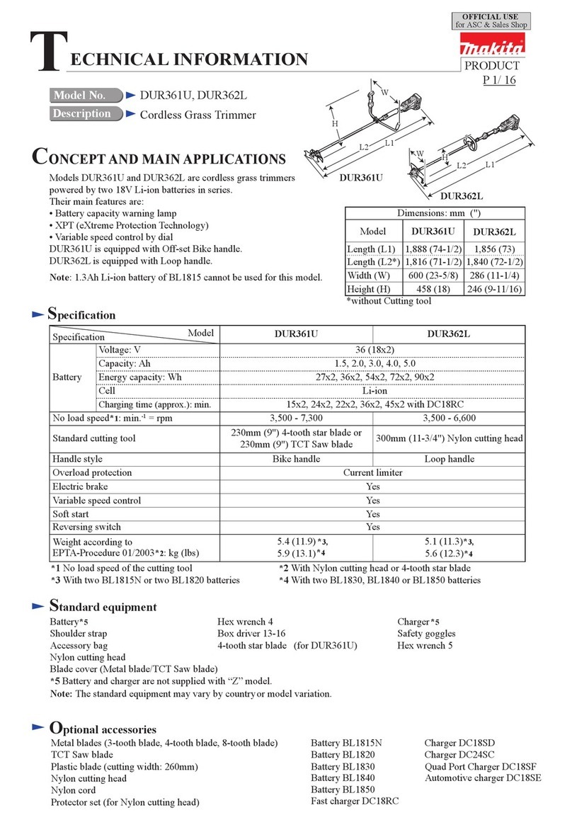
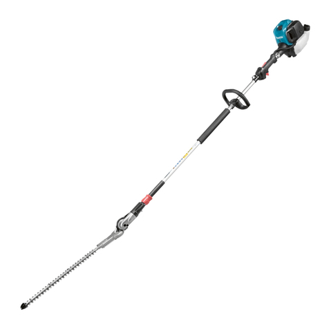
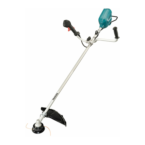
Makita UR3500 User manual

GB Electric Grass Trimmer Instruction Manual
FCoupe-Herbe Electrique Manuel d’instructions
DElektro-Trimmer Gebrauchsanleitung
ITosaerba elettrico Istruzioni per l’uso
NL Elektrische grastrimmer Gebruiksaanwijzing
ECortadora de Cesped Manual de instrucciones
PAparador de Grama Elétrico Manual de instruções
DK Elektrisk græstrimmer Brugervejledning
GR Ηλεκτρικό κουρευτικό γκαζόν Εγχειρίδιο οδηγιών
TR Elektrikli Çim Biçme Makinesi Kullanım Kılavuzu
SElektrisk grästrimmer Bruksanvisning
NElektrisk gresstrimmer Bruksanvisning
FIN Sähkökäyttöinen ruohotrimmeri Käyttöohje
LV Elektriskais zāles trimmeris Lietošanas rokasgrāmata
LT Elektrinė žoliapjovė Naudojimo instrukcija
EE Elektriline murutrimmer Kasutusjuhend
PL Wykaszarka Elektryczna Instrukcja obsługi
HU Elektromos fűnyíró Használati útmutató
SK Elektrická kosačka na trávu Návod na obsluhu
CZ Elektrický vyžínač Návod k použití
SI Električna kosilnica na nitko Navodila za uporabo
AL Kositës Elektrik i Barit Manual Udhëzimi
BG Електрически тример за трева Упътване за работа
HR Električni trimer za travu Upute za korištenje
MK Електрични ножици за трева
(тример) Упатство за работа
RO Trimmer electric pentru iarbă Manual de instrucţiuni
RS Електрични тример за траву Упутство за употребу
RUS
Электрокоса Инструкция по эксплуатации
UA Електротример Інструкція з експлуатації
AR
UR3500
UR3501

2
1
10
6
3
4
2
5
8
11
7
9
4
5
12

3
1
8
14
13
15
17
18
16
19
20
21
22

4
23
18

5
1 Cableholder
2 Powersupplycord(theshape
maydifferfromcountryto
country)
3 Rearhandle
4 Lock-offlever
5 Switchtrigger
6 Fronthandle
7 Hanger(suspensionpoint)
8 Barrier
9 Cuttingtoolguard(protector)
10 Cuttingtool
11 Shoulderharness
12 Mosteffectivecuttingarea
13 Handle
14 Rubberpart
15 Protector
16 Cup
17 Eyelets
18 Spool
19 Lockscrew
20 Cordcutter
21 Cover
22 Hanger
23 80–100mm
Model UR3500 UR3501
Typeofhandle Loophandle
Overalllength 1,550mm
Netweight 4.3kg
Continuousratinginput 700W 1,000W
Noloadspeed 6,500min–1 6,500min–1
Applicablecuttingtool Nyloncuttinghead
Cuttingwidth 350mm
Safetyclass / II
• Duetoourcontinuingprogramofresearchanddevelopment,thespecicationshereinaresubjecttochangewithout
notice.
• Specicationsmaydifferfromcountrytocountry.
• WeightaccordingtoEPTA-Procedure01/2003
Soundpressurelevelaverage Soundpowerlevelaverage
Applicablestandard
Model LPA(dB(A)) UncertaintyK
(dB(A)) LwA(dB(A)) UncertaintyK
(dB(A))
UR3500 81.6 2.5 93.75 1.46 EN50636-2-91:2014
UR3501 79.8 2.5 93.4 1.61
• Wearearprotection.
Frontgrip Reargrip Applicablestandardor
directive
Model ah(m/s2)UncertaintyK
(m/s2) ah(m/s2) UncertaintyK
(m/s2)
UR3500 2.272 1.5 2.222 1.5 EN50636-2-91:2014
UR3501 2.268 1.5 2.248 1.5
• The declared vibration emission value has been
measuredinaccordancewiththestandardtestmethod
andmaybeusedforcomparingonetoolwithanother.
• The declared vibration emission value may also be
usedinapreliminaryassessmentofexposure.
• Thevibrationemissionduringactualuseofthepower
tool can differ from the declared emission value
dependingonthewaysinwhichthetoolisused.
• Be sure to identify safety measures to protect the
operatorthatarebasedonanestimationofexposurein
theactualconditionsofuse(takingaccountofallparts
oftheoperatingcyclesuchasthetimeswhenthetool
isswitchedoffandwhenitisrunningidleinadditionto
thetriggertime).

6
Thefollowingshowthesymbolsusedfortheequipment.
Besurethatyouunderstandtheirmeaningbeforeuse.
• Takeparticularcareandattention.
• Readinstructionmanual.
• Danger;beawareofthrownobjects.
• The distance between the tool and
bystandersmustbeatleast15m.
360°
• Keepbystandersaway.
15m(50FT)• Keepdistanceatleast15m.
• Wear a helmet, goggles and ear
protection.
• Wearprotectivegloves.
• Wear sturdy boots with nonslip
soles. Steeltoed safety boots are
recommended.
• Donotexposetomoisture.
• Disconnectthemainsplugifthecord
isdamagedorentangled.
• Donotuseblade.
• DOUBLEINSULATION
• OnlyforEUcountries
Donotdisposeofelectricequipment
together with household waste
material!
In observance of the European
Directive, on Waste Electric and
Electronic Equipment and its
implementation in accordance with
national law, electric equipment
that have reached the end of their
life must be collected separately
and returned to an environmentally
compatiblerecyclingfacility.
DesignationofMachine:
ElectricGrassTrimmer
ModelNo./Type:UR3500,UR3501
Specications:see“SPECIFICATIONS”table.
2000/14/EC,2006/42/EC,2004/108/EC
Theyaremanufacturedinaccordancewiththefollowing
standardorstandardizeddocuments:
EN60335-1, EN50636-2-91, EN62233,
EN55014-1, EN55014-2, EN61000-3-2,
EN61000-3-3
The technical le in accordance with 2006/42/EC is
availablefrom:
Makita,Jan-BaptistVinkstraat2,3070,Belgium
The conformity assessment procedure required by
Directive2000/14/ECwasinAccordancewithannexVI.
NotiedBody:
SociétéNationaledeCerticationetd’Homologation
11,ruedeLuxembourgL-5230Sandweiler
Identicationnumber0499
ModelUR3500
MeasuredSoundPowerLevel:93.75dB(A)
GuaranteedSoundPowerLevel:96dB(A)
ModelUR3501
MeasuredSoundPowerLevel:93.4dB(A)
GuaranteedSoundPowerLevel:96dB(A)
30.1.2015
YasushiFukaya
Director
Makita,Jan-BaptistVinkstraat2,3070,Belgium

7
Failure to follow the warnings and
instructions may result in electric shock, re and/or
seriousinjury.
1.
2.
3.
4.
5.
6.
7.
8.
9.
10.
11.
12.
13.
14.
15.
16.
17.
1.
1.
2.
3.
1.
2.
Unmodied plugs and matching outlets will
reduceriskofelectricshock.
3.
Thereisanincreasedriskofelectric
shockifyourbodyisearthedorgrounded.
4.
Damaged or entangled cords
increasetheriskofelectricshock.
5.
Useof
acordsuitable foroutdooruse reducestherisk of
electricshock.
6.
UseofanRCDreducestherisk
ofelectricshock.
7.
8. Beforeuse,checkthesupplyandextensioncordfor
signsofdamageorageing.
9. Ifthecordbecomesdamagedduringuse,disconnect
thecordfromthesupplyimmediately.
8
10. Do not use the tool if the cords are damaged or
worn.
11. Keepextensioncordawayfromcuttingelements.
1.
2.
3.
4.
5.
1.
2.
3.
4.
5.
6.
7.
8.
9.
10.
11.
12.
13.
14.
15.
16.
−
−
−
−
−
−
17.
1.
2.
3.
4.
5.
6.
7.
8.
9.
10.

9
•
Failuretoswitchoffandunplug
may result in serious personal injury from accidental
start-up.
•
Operatinga
tool with a switch that does not actuate properly can
leadtolossofcontrolandseriouspersonalinjury.
To prevent the switch trigger from being accidentally
pulled,alock-offleverisprovided.
Tostartthetool,slidethelock-offleverforwardandthen
pulltheswitchtrigger.Releasetheswitchtriggertostop.
• Donotattempttobumpfeedtheheadwhilethetoolis
operatingatahighRPM.BumpfeedingatahighRPM
maycausedamagetothenyloncuttinghead.
• Thebumpfeedwillnotoperateproperlyiftheheadis
notrotating.
The nylon cutting head is a dual grass trimmer head
providedwithabump&feedmechanism.
Tofeedoutthenyloncord,bumpthecuttingheadagainst
thegroundwhilethecuttingheadisrotating.
• Ifthenyloncorddoesnotfeedoutwhilebumpingthe
head, rewind/replace the nylon cord by following the
proceduresdescribedunder“Maintenance.”
Makeasmallloopofpowercable,andhangitontothe
cableholder.
•
Failuretoswitchoffandunplugmayresultinserious
personalinjuryfromaccidentalstart-up.
•
Operation of the tool in a partially
assembledstatemayresultinseriouspersonalinjury
fromaccidentalstart-up.
• Donotremoveorshrinkthespacer.Thespacerkeeps
a certain distance between both hands. Setting the
grip/barrier assembly close to the other grip beyond
thelengthofthespacermaycauselossofcontroland
seriouspersonalinjury.
Fitthehandleandthebarrierontotherubberpartonthe
shaft pipe.Adjust the location of the handle, and then
tightenthemwithfourbolts.
•
Failuretodosocancauseseriouspersonal
injury.
• Takecarenottoinjureyourselfonthecutterforcutting
thenyloncord.
1. Fittheprotectorontotheshaft.
2. Alignthe hole of the protectoralong theslit of the
metalpartontheshaft.
3. Tightenthemwiththebolt.
• Besuretousegenuinenyloncuttinghead.
• Removethecoveronthecordcutterbeforeuse.
Turnthe toolupside down sothat youcan replace the
nyloncuttingheadeasily.
1. Fitthecupontotheaxis.
2. Putthenyloncordsthroughtheeyeletstocomeout
ofthecup.
3. Fitthespoolontheaxis.
4. Pressthespoolintothecup.
5. Holdthecupandthespool,andthentightenthem
withthelockscrewbyturningitclockwise.
To remove the nylon cutting head, turn the lock screw
counterclockwisewhileholdingthecup.
•
Correct positioning of the tool allows for maximum
control and will reduce the risk of serious personal
injury.
•
Use of a damaged nylon cutting head could result in
seriouspersonalinjury.
Puttheshoulderharnessonyourleftshoulderbyputting
yourheadandrightarmthroughitandkeepthetoolon
yourrightsidewhilealwayskeepingthebarrierinfront
ofyourbody.

10
Adjusttheharnesslengthsothatthecuttingtooliskept
parallelwiththeground.
Connectthehangerandtheharness.
•
Failureto
keepcontrolofthetoolcouldresultinseriousinjuryto
thebystanderandtheoperator.
To change the hanger position, loosen the bolt on the
hanger.Thenmovethehanger.
Afteradjustingthehangerposition,tightentheboltwith.
•
Failure to switch off
andunplugmayresultinseriouspersonalinjuryfrom
accidentalstart-up.
• Never use gasoline, benzine, thinner, alcohol or the
like.Discoloration,deformationorcracksmayresult.
•
Failuretoproperly
securethenyloncuttingheadmaycauseittoyapart
resultinginseriouspersonalinjury.
1. Remove the lock screw by turning it
counterclockwise.
2. Removethespoolandthecup.Andremovetheold
nyloncordfromthespool.
3. Cutanyloncordin3–6m.Foldthecuttingcordin
twohalves, leaveone of halflonger 80– 100mm
thananother.
4. Hookthemiddleofthenewnyloncordtothenotch
locatedatthecenterofthespoolbetweenthetwo
channelsprovidedforthenyloncord.
5. Wind both ends rmly along the channels in the
directionindicatedbyarrowmarkonthespool.
6. Install the nylon cutting head as described in this
instructionmanual.
To maintain product SAFETY and RELIABILITY,
repairs,anyothermaintenanceoradjustmentshouldbe
performedbyMakitaAuthorizedServiceCenters,always
usingMakitareplacementparts.

11
Parts: Interval: Howto:
Powercord Everytimebeforeuse Visuallyinspectwhetheritisnotbadlywornordamaged.
Ifitisdamaged,askyourlocalservicecenterforrepair.
Auxiliaryhandlescrew Everytimebeforeuse Checkwhetherscrewisnotloose.Tightenthescrewifit
isloose.Replacethescrewifitisdamaged.
Cuttingtoolguard(protector) Everytimebeforeuse
Checkwhetherscrewisnotloose,whetherprotectoris
notdamaged.Tightenthescrewifitisloose.Replacethe
protectorifitisdamaged.
Nyloncuttinghead Every10h Visuallyinspectwhetheritisnotbadlywornordamaged.
Ifitisdamaged,replaceit.
Beforeaskingforrepairs,conductyourowninspectionrst.Ifyoundaproblemthatisnotexplainedinthemanual,
donotattempttodismantlethetool.Instead,askMakitaAuthorizedServiceCenters,alwaysusingMakitareplacement
partsforrepairs.
Malfunctionstatus Cause Action
Motordoesnotrun.
Powermainsisnotpluggedin. Pluginthemains.
Powercablebroken. Ask your local authorized service
centerforrepair.
The drive system does not work
correctly.
Motorstopsrunningafteralittleuse. Overheating. Stopusingoftooltoallowittocool
down.
ItdoesnotreachmaximumRPM. The drive system does not work
correctly.
Ask your local authorized service
centerforrepair.
Cuttingtooldoesnotrotate:
stopthemachineimmediately!
Foreign object such as a branch is
jammedbetweentheguardandthe
nyloncuttinghead.
Removetheforeignobject.
The drive system does not work
correctly.
Ask your local authorized service
centerforrepair.
Abnormalvibration:
stopthemachineimmediately!
Oneendofthenyloncordhasbeen
broken.
Bumpthenyloncuttingheadagainst
the ground while it is rotating to
causethecordtofeed.
The drive system does not work
correctly.
Ask your local authorized service
centerforrepair.
Cuttingtoolandmotorcannotstop:
Disconnectthemainsimmediately! Electricorelectronicmalfunction.
Disconnectthemainsandaskyour
local authorized service center for
repair.
• Theseaccessories orattachmentsare recommended
forusewithyourMakitatoolspeciedinthismanual.
Theuseofanyotheraccessoriesorattachmentsmight
presentariskofinjurytopersons.Onlyuseaccessory
orattachmentforitsstatedpurpose.
If you need any assistance for more details regarding
theseaccessories,askyourlocalMakitaServiceCenter.
• Nyloncuttinghead
• Nyloncord(cuttingline)
• Shoulderharness
• Some items in the list may be included in the tool
packageasstandardaccessories.Theymaydifferfrom
countrytocountry.

12
1 Supportdecâble
2 Cordond’alimentation(laforme
peutvarierd’unpaysàl’autre)
3 Poignéearrière
4 Boutondesécurité
5 Gâchette
6 Poignéeavant
7 Anneaudesuspension
8 Protection
9 Déecteurdel’outildecoupe
10 Outildecoupe
11 Harnaissimple
12 Zonedecoupelaplusefcace
13 Poignée
14 Partierecouvertede
caoutchouc
15 Déecteur
16 Coupelle
17 Œillets
18 Bobine
19 Écroudeblocage
20 Coupe-l
21 Cachedeprotection
22 Anneaudesuspension
23 80–100mm
Modèle UR3500 UR3501
Typedepoignée Poignéecirculaire
Longueurtotale 1550mm
Poidsnet 4,3kg
Puissanceenrégimecontinu 700W 1000W
Vitesseàvide 6500min–1 6500min–1
Outildecoupeadapté Têtedecoupeàlnylon
Largeurdecoupe 350mm
Catégoriedesécurité / II
• Étantdonnél’évolutionconstantedenotreprogrammederechercheetdéveloppement,lesspécicationscontenues
danscemanuelsontmodiablessanspréavis.
• Lesspécicationspeuventvariersuivantlespays.
• PoidsselonlaprocédureEPTA01/2003
Niveaudepressionacoustique
moyen
Niveaudepuissanceacoustique
moyen Normeapplicable
Modèle LPA(dB(A)) IncertitudeK
(dB(A)) LwA(dB(A)) IncertitudeK
(dB(A))
UR3500 81,6 2,5 93,75 1,46 EN50636-2-91:2014
UR3501 79,8 2,5 93,4 1,61
• Portezdesprotecteursd’oreilles.
Poignéeavant Poignéearrière Normeoudirective
applicable
Modèle ah(m/s2)IncertitudeK
(m/s2) ah(m/s2) IncertitudeK
(m/s2)
UR3500 2,272 1,5 2,222 1,5 EN50636-2-91:2014
UR3501 2,268 1,5 2,248 1,5
• Lavaleurd’émissiondevibrationdéclaréeaétémesurée
conformémentàlaméthoded’essainormaliséeetpeut
êtreutiliséepourcomparerdifférentsoutils.
• Lavaleurd’émissiondevibrationdéclaréepeutaussi
êtreutiliséepourréaliseruneévaluationpréliminairede
l’exposition.
• L’émission de vibration pendant l’utilisation réelle de
l’outil électrique peut différer de la valeur d’émission
déclaréeenfonctiondelafaçondontl’outilestutilisé.
• Assurez-vous que les mesures de sécurité visant à
protégerl’opérateursontbaséessuruneestimationde
l’expositiondans les conditionsnormales d’utilisation,
en tenant compte de toutes les phases du cycle de
fonctionnement, y compris les périodes d’arrêt et de
fonctionnementàvide.

13
Lessymboles suivantsvoussignalentdes informations
importantesrelativesàl’équipement.Assurez-vousque
vouscomprenezleursignicationavantutilisation.
• Soyezvigilant.
• Lisezlemanueld’instruction.
• Danger, risque de projection
d’objets.
• Distanceminimumentrel’outiletles
personnesprésentes:15m.
360°
• Éloignezlespersonnesprésentes.
15m(50FT)• Restez à une distance de 15m
minimum.
• Portez un casque, des lunettes
de sécurité et des protecteurs
d’oreilles.
• Portezdesgantsdeprotection.
• Portez des chaussures solides à
semellesantidérapantes.Leportde
chaussuresdesécuritéàembouten
acierestrecommandé.
• N’exposezpasl’outilàl’humidité.
• Débranchezlaprisedel’alimentation
si le cordon est endommagé ou
emmêlé.
• N’utilisezpasdelame.
• DOUBLEISOLATION
• Pourl’UEuniquement
Ne jetez pas les équipements
électriques dans les ordures
ménagères!
Conformément à la directive
européenne relative aux déchets
d’équipements électriques et
électroniques (DEEE) et à sa
transposition dans la législation
nationale, les équipements
électriques qui ont atteint la n
de leur durée de service doivent
être collectés à part et être soumis
à un recyclage respectueux de
l’environnement.
Désignationdelamachine:
Coupe-HerbeElectrique
N°demodèle/type:UR3500,UR3501
Spécications: se référer au tableau
«SPÉCIFICATIONS».
2000/14/CE,2006/42/CE,2004/108/CE
etest(sont)fabriquée(s)conformémentauxnormesou
auxdocumentsnormaliséssuivants:
EN60335-1, EN50636-2-91, EN62233,
EN55014-1, EN55014-2, EN61000-3-2,
EN61000-3-3
La documentation technique conforme à la norme
2006/42/CEestdisponibleauprèsde:
Makita,Jan-BaptistVinkstraat2,3070,Belgique
Laprocédured’évaluationdelaconformitérequiseparla
Directive2000/14/CEaétéréaliséeenconformitéavec
l’annexeVI.
Organismenotié:
SociétéNationaledeCerticationetd’Homologation
11,ruedeLuxembourgL-5230Sandweiler
Numérod’identication0499
ModèleUR3500
Niveaudepuissanceacoustiquemesuré:93,75dB(A)
Niveaudepuissanceacoustiquegaranti:96dB(A)
ModèleUR3501
Niveaudepuissanceacoustiquemesuré:93,4dB(A)
Niveaudepuissanceacoustiquegaranti:96dB(A)
30.1.2015
YasushiFukaya
Directeur
Makita,Jan-BaptistVinkstraat2,3070,Belgique

14
Le non-
respectdesmisesengardeetdesinstructionspeut
entraîner un choc électrique, un incendie et/ou des
blessuresgraves.
1.
2.
3.
4.
5.
6.
7.
8.
9.
10.
11.
12.
13.
14.
15.
16.
17.
1.
1.
2.
3.
1.
2.
L’utilisation de ches non modiées et de prises
du type correspondant réduit les risques de choc
électrique.
3.
Lesrisquesdechoc
électriqueaugmententsivotrecorpssetrouvemisà
laterreouàlamasse.

15
4.
Les
cordonsendommagésouemmêlésaugmententles
risquesdechocélectrique.
5.
L’utilisationd’unerallongeconçuepour
l’extérieurréduitlesrisquesdechocélectrique.
6.
L’utilisationd’undisjoncteurdifférentiel
réduitlesrisquesdechocélectrique.
7.
8. Avant toute utilisation, inspectez le cordon
d’alimentation et la rallonge pour vérier qu’ils ne
présentent aucun signe de détérioration ou de
vieillissement.
9. Si le cordon d’alimentation est endommagé en
coursd’utilisation,débranchez-leimmédiatementde
l’alimentation.
10. N’utilisezpasl’outilsilescordonssontendommagés
ouusés.
11. Tenezlarallongeàl’écartdesélémentsdecoupe.
1.
2.
3.
4.
5.
1.
2.
3.
4.
5.
6.
7.
8.
9.
10.
11.
12.
13.
14.
15.

16
16.
−
−
−
−
−
−
17.
1.
2.
3.
4.
5.
6.
7.
8.
9.
10.
•
Si vous ne mettez pas l’outil hors
tensionetsivousneledébranchezpas,sondémarrage
accidentelpeutentraîneruneblessuregrave.
•
L’utilisation d’un outil dont
l’interrupteur ne fonctionne pas correctement peut
entraînerlapertedemaîtrisedel’outiletdesblessures
graves.
Le bouton de sécurité permet d’éviter de tirer
accidentellementsurlagâchette.
Pourdémarrerl’outil,faitesglisserleboutondesécurité
versl’avantpuistirezsurlagâchette.Pourarrêterl’outil,
libérezlagâchette.
• N’essayezpasd’utiliserlesystèmed’avanceparchoc
lorsque l’outil fonctionne à régime élevé. L’utilisation
dusystèmed’avanceparchoc à régimeélevérisque
d’endommagerlatêtedecoupeàlnylon.
• Le système d’avance par choc ne fonctionne pas
correctementsilatêten’estpasenrotation.
Latêtedecoupeàlnylonestunetêtededésherbage
doubleéquipéed’unsystèmed’avanceparchoc.
Pourfaireavancerlelnylon,frappezlatêtedecoupe
surlesol,latêteétantenrotation.
• Silelnylonn’avancepaslorsquevousfrappezlatête
surlesol,rembobinez/remplacezlelnylonensuivant
lesprocéduresdécritesdans«Entretien».
Faites une petite boucle sur le câble d’alimentation, et
accrochez-lasurlesupportdecâble.
•
Sivousnemettezpasl’outilhorstension
et si vous ne le débranchez pas, son démarrage
accidentelpeutentraîneruneblessuregrave.
•
L’utilisationdel’outilpartiellementmontépeut
entraîner une grave blessure suite à un démarrage
accidentel.

17
• N’enlevez pas l’entretoise, ne la raccourcissez pas.
L’entretoise maintient une certaine distance entre les
deux mains. Une distance de montage inférieure à
la longueur de l’entretoise entre l’ensemble poignée/
protectionetl’autrepoignéepeutentraînerlapertede
maîtrisedel’outiletdesblessuresgraves.
Placezlapoignéeetlaprotectionsurlapartierecouverte
de caoutchouc de l’arbre. Réglez l’emplacement de
la poignée, et xez l’ensemble en place avec quatre
boulons.
•
Lenon-respectdecetteconsigne
peutentraînerdesblessuresgraves.
• Veillez à ne pas vous blesser avec le coupe-l du l
nylon.
1. Placezledéecteursurl’arbre.
2. Alignezletroududéecteuraveclafentedelapartie
métalliquedel’arbre.
3. Assemblez-lesavecleboulon.
• Veillez à utiliser une authentique tête de coupe à l
nylon.
• Enlevez le cache de protection du coupe-l avant
utilisation.
Retournezl’outilanderemplacerlatêtedecoupeàl
nylonfacilement.
1. Placezlacoupellesurl’axe.
2. Faites sortir les ls nylon par les œillets de la
coupelle.
3. Placezlabobinesurl’axe.
4. Appuyezsurlabobinepourlafairerentrerdansla
coupelle.
5. Maintenez la coupelle et la bobine, puis bloquez-
lesentournantl’écroudeblocagedanslesensdes
aiguillesd’unemontre.
Pourdémonterlatêtedecoupeàlnylon,tournezl’écrou
de blocage dans le sens inverse des aiguilles d’une
montreenmaintenantlacoupelle.
•
Lebon
positionnementdel’outilpermetuncontrôlemaximalet
réduitlerisquedeblessuregrave.
•
L’utilisation d’une tête de coupe
à l nylon endommagée peut entraîner une blessure
grave.
Placez le harnais sur votre épaule gauche en passant
votretêteetvotrebrasdroitàl’intérieur.Maintenezl’outil
à votre droite an que la protection se trouve toujours
devantvous.
Ajustezlalongueurduharnaisanquel’outildecoupe
soittoujoursparallèleausol.
Fixezleharnaissurl’anneaudesuspension.
•
Laperte
decontrôledel’outilprésentedesrisquesdeblessure
gravepourl’opérateuretlespersonnesàproximité.
Pour modier la position de l’anneau de suspension,
desserrez le boulon se trouvant sur celui-ci. Déplacez
ensuitel’anneaudesuspension.
Réglez la position de l’anneau de suspension, puis
resserrezleboulon.
•
Si vous
ne mettez pas l’outil hors tension et si vous ne le
débranchez pas, son démarrage accidentel peut
entraîneruneblessuregrave.
• N’utilisezjamaisd’essence,benzine,diluant,alcoolou
autreproduitsimilaire.Celarisqueraitdeprovoquerla
décoloration,ladéformationoulassurationdel’outil.

18
•
Une tête de coupe à l nylon mal xée risque d’être
éjectéeetdeprovoquerdesblessuresgraves.
1. Retirez l’écrou de blocage en le tournant dans le
sensinversedesaiguillesd’unemontre.
2. Enlevezlabobineetlacoupelle.Enlevezensuitele
vieuxldelabobine.
3. Coupez un morceau de l nylon de longueur
3–6m. Pliez le l de coupe en deux parties
inégales, l’une étant plus longue que l’autre de
80–100mm.
4. Accrochez la boucle du nouveau l nylon sur
l’encoche située au centre de la bobine, entre les
deuxgorgesdestinéesaulnylon.
5. Enroulezenserrantleslsdanslesgorgesselonla
directionindiquéeparlaèchesurlabobine.
6. Installezlatêtedecoupeàlnyloncommeindiqué
dansleprésentmanuel.
PourmaintenirlaSÉCURITÉetlaFIABILITÉduproduit,
les réparations, travaux d’entretien et autres réglages
doiventêtreeffectuésdansuncentredeserviceMakita
agréé, exclusivement avec des pièces de rechange
Makita.
Pièces: Périodicité: Opération:
Cordond’alimentation Avantchaque
utilisation
Vériezvisuellementl’étatdelapièce(usureou
détériorationimportantes).Sielleestendommagée,
demandezàvotrecentretechniquederéaliserles
réparations.
Visdelapoignéeauxiliaire Avantchaque
utilisation
Vériezsilavisestbienserrée.Serrezlavissielleest
desserrée.Remplacezlavissielleestendommagée.
Déecteurdel’outilde
coupe
Avantchaque
utilisation
Vériezsilavisestbienserréeetsiledéecteuresten
bonétat.Serrezlavissielleestdesserrée.Remplacezle
déecteurs’ilestendommagé.
Têtedecoupeàlnylon Toutesles10heures
Vériezvisuellementl’étatdelapièce(usureou
détériorationimportantes).Remplacez-lasielleest
endommagée.

19
Avant de faire faire une réparation, effectuez votre propre inspection. Si vous rencontrez un problème non décrit
dansleprésentmanuel,n’essayezpasdedémonterl’outil.Conez-leàuncentretechniqueagrééMakita,quiutilise
toujoursdespiècesderechangeMakitapourlesréparations.
Dysfonctionnement Cause Remède
Lemoteurnetournepas.
La prise n’est pas branchée sur
l’alimentationélectrique.
Branchez la prise sur l’alimentation
électrique.
Lecâbled’alimentationestcassé. Demandez à un centre technique
agrééderéaliserlesréparations.
Le système d’entraînement ne
fonctionnepascorrectement.
Le moteur arrête de tourner après
unecourteutilisation. Surchauffe. Arrêtez d’utiliser l’outil et laissez-le
refroidir.
Impossible d’atteindre le plein
régime.
Le système d’entraînement ne
fonctionnepascorrectement.
Demandez à un centre technique
agrééderéaliserlesréparations.
L’outildecoupenetournepas:
arrêtezimmédiatementlamachine!
Un corps étranger (par exemple
une branche) est coincé entre le
déecteur et la tête de coupe à l
nylon.
Enlevezlecorpsétranger.
Le système d’entraînement ne
fonctionnepascorrectement.
Demandez à un centre technique
agrééderéaliserlesréparations.
Vibrationsanormales:
arrêtezimmédiatementlamachine!
Unedesextrémitésdulnylons’est
cassée.
Pour faire avancer le l nylon,
frappezlatêtedecoupesurlesol,la
têteétantenrotation.
Le système d’entraînement ne
fonctionnepascorrectement.
Demandez à un centre technique
agrééderéaliserlesréparations.
L’outil de coupe et le moteur ne
s’arrêtentpas:
débranchezimmédiatementl’outilde
l’alimentationélectrique!
Dysfonctionnement électrique ou
électronique.
Débranchez immédiatement l’outil
de l’alimentation électrique et
demandez à un centre technique
agrééderéaliserlesréparations.
• Ces accessoires ou pièces sont recommandés pour
l’utilisation avec l’outil Makita spécié dans ce mode
d’emploi.L’utilisationdetoutautreaccessoireoupièce
peut comporter un risque de blessure. N’utilisez les
accessoiresoupiècesqu’auxnsauxquellesilsontété
conçus.
Si vous désirez obtenir plus de détails concernant ces
accessoires, veuillez contacter le centre de service
Makitaleplusproche.
• Têtedecoupeàlnylon
• Filnylon(ldecoupe)
• Harnaissimple
• Ilsepeutquecertainsélémentsdelalistesoientfournis
avecl’outilentantqu’accessoiresstandard.Ilspeuvent
varierd’unpaysàl’autre.

20
1 Kabelhalter
2 Netzkabel(dieFormkannje
nachLandunterschiedlichsein)
3 HintererHandgriff
4 Einschaltsperrhebel
5 Elektronikschalter
6 VordererHandgriff
7 Aufhänger(Aufhängepunkt)
8 Sperre
9 Schneidwerkschutz
(Schutzhaube)
10 Schneidwerkzeug
11 Schultergurt
12 EffektivsterSchnittbereich
13 Handgriff
14 Gummiteil
15 Schutzhaube
16 Becher
17 Ösen
18 Spule
19 Sicherungsschraube
20 Fadenschneider
21 Abdeckung
22 Aufhänger
23 80–100mm
Modell UR3500 UR3501
Handgrifftyp Ringgriff
Gesamtlänge 1550mm
Nettogewicht 4,3kg
Dauer-Nennleistung 700W 1000W
Leerlaufdrehzahl 6500min–1 6500min–1
Verwendbares
Schneidwerkzeug Nylonfadenkopf
Schnittbreite 350mm
Schutzart / II
• AufgrundunseresDauerprogrammsderForschungundEntwicklungunterliegendiehierangegebenentechnischen
DatenÄnderungohneVorankündigung.
• DietechnischenDatenkönnenvonLandzuLandunterschiedlichsein.
• GewichtnachEPTA-Verfahren01/2003
Durchschnittlicher
Schalldruckpegel
Durchschnittlicher
Schallleistungspegel Zutreffender
Standard
Modell LPA(dB(A)) UnsicherheitK
(dB(A)) LwA(dB(A)) UnsicherheitK
(dB(A))
UR3500 81,6 2,5 93,75 1,46 EN50636-2-91:2014
UR3501 79,8 2,5 93,4 1,61
• EinenGehörschutztragen.
VordererGriff HintererGriff Zutreffender
Standardoder
Richtlinie
Modell ah(m/s2)UnsicherheitK
(m/s2) ah(m/s2) UnsicherheitK
(m/s2)
UR3500 2,272 1,5 2,222 1,5 EN50636-2-91:2014
UR3501 2,268 1,5 2,248 1,5
• Der angegebene Vibrationsemissionswert wurde im
Einklang mit der Standardprüfmethode gemessen
und kann für den Vergleich zwischen Geräten
herangezogenwerden.
• Der angegebene Vibrationsemissionswert kann
auch für eine Vorbewertung des Gefährdungsgrads
verwendetwerden.
• Die Vibrationsemission während der tatsächlichen
Benutzung des Elektrowerkzeugs kann je nach der
Benutzungsweise des Gerätes vom angegebenen
Emissionswertabweichen.
• Identizieren Sie Sicherheitsmaßnahmen zum
Schutz des Benutzers anhand einer Schätzung
des Gefährdungsgrads unter den tatsächlichen
Benutzungsbedingungen (unter Berücksichtigung
aller Phasen desArbeitszyklus, wie z. B. Ausschalt-
und Leerlaufzeiten des Gerätes zusätzlich zur
Betriebszeit).
This manual suits for next models
1
Table of contents
Languages:
Other Makita Trimmer manuals

Makita
Makita RBC225 User guide

Makita
Makita DUR364L User manual

Makita
Makita EN4950H User guide

Makita
Makita DUH501 User manual

Makita
Makita UR014G User manual

Makita
Makita UR003G User manual

Makita
Makita 4050, 4850, 5550, 6350 Manual

Makita
Makita DUH506 User manual

Makita
Makita DUR141 User manual

Makita
Makita EM2600U Instruction Manual

Makita
Makita UH480D User manual

Makita
Makita UH4570 User manual

Makita
Makita UH4261 User manual

Makita
Makita 3700D User manual

Makita
Makita UR002GD201 User manual

Makita
Makita DUN500W User manual

Makita
Makita UH5580 User manual

Makita
Makita UR006G User manual

Makita
Makita UR014G User manual

Makita
Makita DUR369APT2 User manual