makro Gold Racer User manual


READ CAREFULLY BEFORE OPERATING THE DEVICE!
LEGAL DISCLAIMERS
Comply with the laws and regulations in force within the area while using the device.
Do not use the device in protected or archeological sites and military zones. Notify
any historical and cultural artifacts you find to the concerned authorities.
WARNINGS
GOLD RACER is a state-of-the-art electronic device. Do not assemble or operate the
device before reading the user manual.
Do not keep the device and search coil under extremely low and high temperatures
for extended periods. (Storage Temperature: - 20°C to 60°C / - 4°F to 140°F).
Do not immerse the device and its accessories (except for the search coil) in water or
keep them in excessively humid environments.
Protect the device against impacts that may occur during shipping in particular.
GOLD RACER may only be disassembled and repaired by authorized service centers.
Disassembling the device for any reason voids the warranty.

Table of Contents
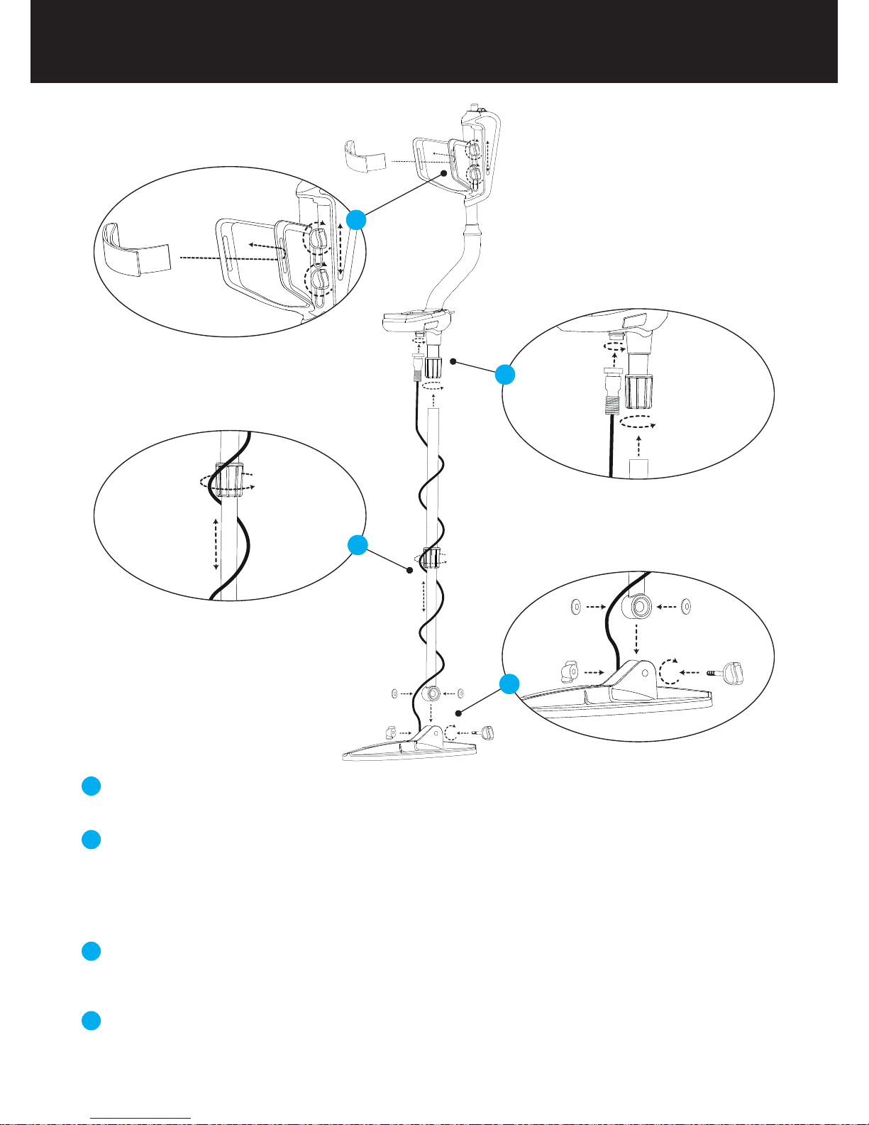
Assembly ..........................................................................................................................................................................................................................
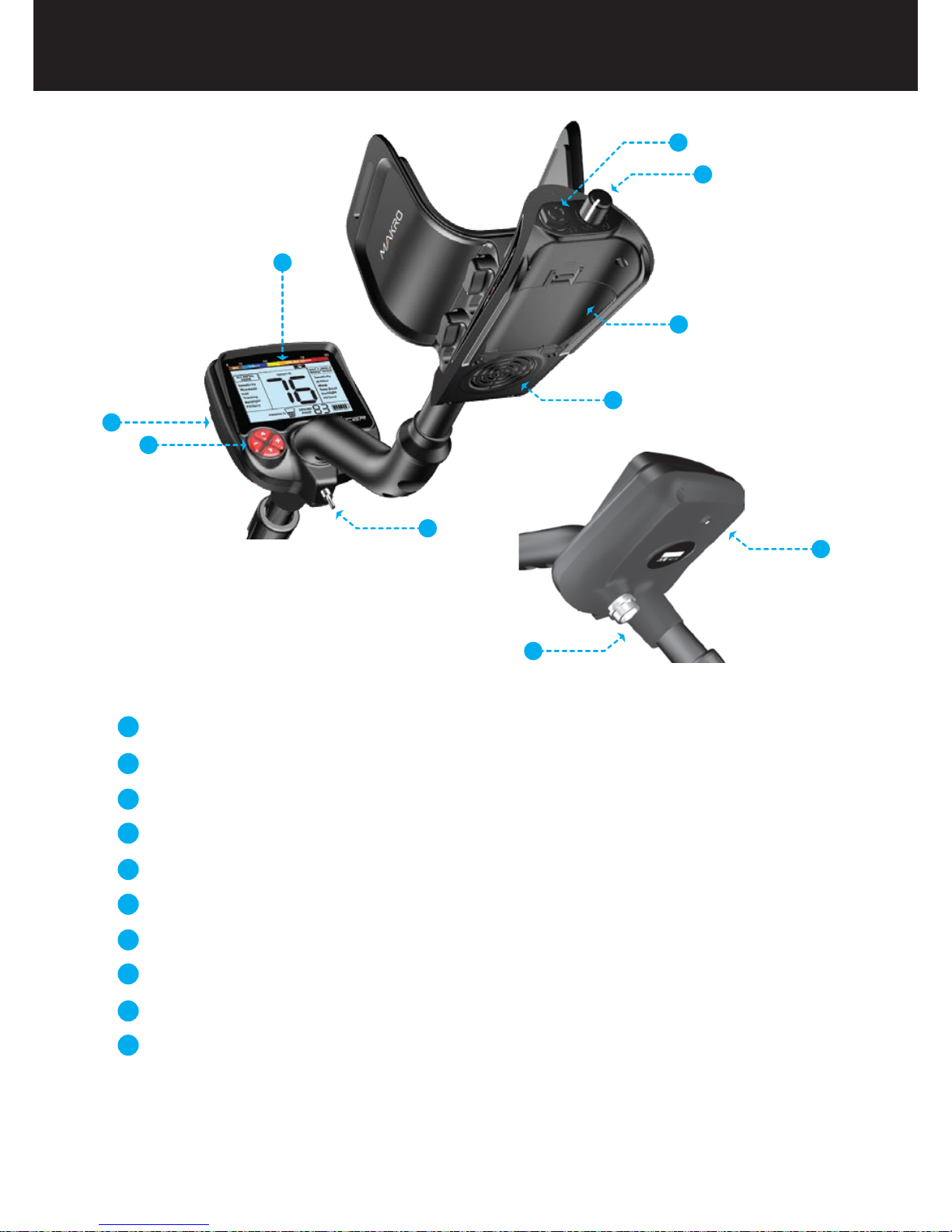
General Description of the Device ........................................................................................................................................
Battery Details ........................................................................................................................................................................................................
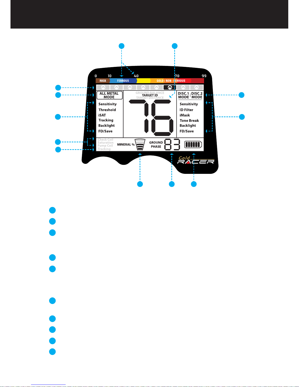
Display..................................................................................................................................................................................................................................
Correct Use....................................................................................................................................................................................................................
Quick Guide.................................................................................................................................................................................................................
Menu........................................................................................................................................................................................................................................
Search Modes.................................................................................................................................................................................................
Settings Comman to All Modes................................................................................................................................................
Ground Balance........................................................................................................................................................................................
Sensitivity, iSAT, Threshold and iMask..................................................................................................................
Target ID and ID Filtering..........................................................................................................................................................
Other Settings Not Shown on Screen.............................................................................................................................
Pinpoint................................................................................................................................................................................................................
Target Distance..................................................................................................................................................................................................
Swinging Speed and Target Identification.............................................................................................................
Large or Near-Surface Targets....................................................................................................................................................
False Signals and Reasons.................................................................................................................................................................
Magnetic Mineralization Indicator......................................................................................................................................
Rocks and Searching in Rocky Terrains.............................................................................................................
Tracking and Effects of Rocks...........................................................................................................................................
Metals Under Rocks....................................................................................................................................................................................
Messages...........................................................................................................................................................................................................
Technical Specifications.......................................................................................................................................................................
1
2
3
4
5
6
7
7-10
11
12-15
16-17
17-18
19
19-20
20
20
20
21
21
21-22
22-23
23
23-24
24

Insert the washers as shown on the telescopic shaft. Install the telescopic shaft to its location on
the search coil. Secure by tightening the screw and nut.
Loosen the twist lock before mounting the telescopic shaft to the upper rod. Press down the pin
and engage the pieces together and tighten the twist lock after the pin is clicked into the hole.
Wind the cable of the search coil on the telescopic shaft without stretching too much. Plug the
connector on the cable to the search coil input socket on the system box and secure by
tightening the nut.
Loosen the twist lock of the telescopic shaft to extend or shorten it. Adjust the length of the shaft
by keeping the pin located on the rear pressed down and clicking the pin in any of the holes.
Secure by tightening the twist lock.
Insert the armrest band through its slot as shown in the figure. Loosen the screws and adjust the
armrest position to your comfort by sliding it down or up and secure by tightening the screws.
1
2
3
4
Assembly Page_1
1
3
2
4

General Description of the Device
Display showing all settings and information.
Wireless headphone module jack (wireless headphones are sold separately).
Keypad for navigation among menu options and changing the device settings.
Ground balance and pinpoint trigger.
Speaker.
Battery compartment cover.
On /Off and volume adjustment button.
Wired headphone jack.
Search coil connector socket.
LED flashlight.
1
2
3
4
5
6
7
8
9
10
9
10
Page_2
1
2
3
4
5
6
7
8

Battery Details
The device is supplied with 4 pieces of AA Alkaline batteries.
To remove the battery compartment cover, press on the latch and pull out. Insert the batteries
observing correct polarity of + (plus) and - (minus).
The device can be used for approximately 25-30 hours when the batteries are fully charged.
Operating time of other brands and types of batteries available on the market may vary.
AA Alkaline batteries are recommended for the best performance. Good quality Ni-MH
rechargeable batteries can be used, too. Rechargeable batteries with high mAh (capacity)
ratings offer extended operating times than batteries with lower rating. We recommend use of
minimum 2500mAh batteries.
Low Battery Level
Battery icon on the display shows the battery life status. When the charge decreases, the bars
inside the battery icon decrease, too. "Lo" message appears on the display when the batteries
are depleted and the device shuts down after a short period.
Page_3

Menu providing access to all settings of the device.
Target ID and color scale.
Cursor indicating the ID of the detected target and its position on the color
scale. It is displayed by itself when the target signal is weak and in a black
box when the signal is strong.
Search modes.
Section which shows the Target ID during search, the ground balance value
during ground balance adjustment and the estimated target depth during
the pinpoint process. Also, the numeric value of any setting selected from
the menu is displayed in this field.
Section which shows the fine tuning value during ground balance
adjustment and current ground balance value during search.
Magnetic mineralization indicator.
Battery level indicator.
Tracking on / off status indicator.
Section which shows the warning messages.
1
3
4
5
6
7
8
9
10
Display
2
Page_4
2
67 8
5
1
10
4
3
9
4
1

Correct Use
Incorrect Handling Correct Handling
Incorrect Use Correct Use
Page_5

Assemble the device as per the instructions on page 1.
Insert the batteries by paying attention to +/- polarity.
Rotate the on/off switch located behind the device clockwise to turn on the
device. This switch also adjusts the volume.
When the device is turned on, it will start in the All Metal mode. You can
change the mode based on the area that you are searching.
To ground balance, push and hold the trigger forward and pump the search
coil up and down 3cm (1.2'') above the ground until a “beep” sound is heard.
You can increase the sensitivity if needed. Increasing the sensitivity will
offer you greater depth. However, if the surroundings or the ground cause
excessive noise in the device, you need to lower the sensitivity setting.
If the device receives a lot of ground noise in the All Metal mode causing a
disruption in the threshold's stability, you can increase the iSAT value.
If the ground is highly mineralized causing the coil to overload, decrease
the sensitivity until the ''Saturation'' message disappears from the screen.
Testing with various metals in discrimination modes is useful for getting
familiar with the sounds produced by the device.
Based on the IDs of the metals you don't want to detect, you can set the ID
Filter and ignore those metals. For instance, if you don’t want to detect
ferrous metals with 20 ID, you can adjust the ID Filter to 21.
You can now start searching.
Since your device operates with the motion principle, swing the search coil
right and left maintaining 5cm (2") distance above the ground. If the search
coil does not move, the device will not provide any warning tones even if
the coil is over a metal target.
When a target is detected, the ID of the target is displayed on the screen
and the cursor indicates its position in the ID and color scale. The device
also produces a warning tone based on the search mode selected.
Upon target detection, you can pinpoint the exact location of the target by
pulling and holding the trigger back.
1
3
4
5
6
7
8
9
10
11
12
13
14
2
Quick Guide
Page_6

3 search modes adapted to different ground conditions and target types are offered by the
GOLD RACER. Names of the search modes are defined as All Metal, DISC.1, and DISC.2 on the
screen. You can easily switch between the modes by using the direction keys during your search.
The name of the selected mode is shown framed on screen. While in settings, the selection
cursor appears on the selected setting and the current mode name is underlined. The settings
for All Metal mode appears on the left side of the screen and the settings for both discrimination
modes appear on the right. Some settings are common to all modes. For more details, please
read the explanations for settings of each mode carefully.
All Metal Mode
It is the deepest mode of the device. Different than the discrimination modes, this mode features
a threshold tone which is continuously heard in the background.
The device does not discriminate targets while in the All Metal mode and detects all targets
(metal, mineralized rocks etc.). ID of the detected target is shown on the display (except for
negative hot rocks) and the same warning tone is provided for all targets. The warning tone
increases in pitch as the target is approached.
Sensitivity, threshold and iSAT settings in this mode are set to default values which provide the
best performance on different terrains. You can modify these settings based on ground
conditions.
Settings for All Metal Mode
Sensitivity
It is the depth setting of the All Metal mode. It is also used to eliminate the ambient
electromagnetic signals from the surrounding environment and noise signals transmitted from
ground.
The device starts in the All Metal mode. You
can change the mode using the +/- buttons.
Select a setting from the menu by using the
up/down buttons. The value of the selected
setting is shown on the display. You can
change the value by using the + and -
buttons.
If up/down and +/- buttons are kept
pressed for a certain period, options and
values change more rapidly.
If no button is pressed for a while after selecting a setting or changing its value, the selection
cursor automatically returns back to the selected mode. Pulling the trigger eliminates the
waiting time.
Menu Page_7
Search Modes

Search Modes
Threshold
This setting is used to adjust the humming sound, referred to as the threshold sound, which is
continuously heard in the background in the All Metal mode. It is used to increase the target
signal, in other words, the depth of the device. For more details, please read Sensitivity,
Threshold, iSAT and iMASK section on pages 16-17.
iSAT
For the All Metal mode to perform accurately, a stable threshold sound is necessary. Changes in
mineralization and soil structure may cause a rise or fall in the background hum and disrupt the
threshold's stability which will result in losing target signals of certain metals such as small gold
nuggets. iSAT feature maintains the steadiness of the threshold by adjusting the speed the
device recovers its threshold sound.
iSAT consists of 10 levels . The device will start at level 6. It is recommended that iSAT should be
increased in high-mineralization and decreased in low mineralization. For more details, please
read Sensitivity, Threshold, iSAT and iMASK section on pages 16-17.
Audio Boost
Ths feature s not ncluded n the settngs on screen. The audio boost switch boosts the sound
of weak signals received from small or deep targets making it easier for you to detect those
uncertain targets. It is recommended that audio boost should be used on a temporary or
as-needed basis because it will not only boost the target signal audio but it will also boost the
loudness of ground noise and false signals along with the threshold hum.
For an instant audio boost, push and hold the (-) button during searching. To exit, just release the
button. If you want to use the audio boost constantly, double click the minus (-) button . The
frame around the ALL METAL MODE text will start blinking indicating that the audio boost is
active. To exit, double click the (-) button again.
NOTE: When you want to use the Audio Boost function, be sure that you are not in the settings
menu and the selection frame is around the ALL METAL MODE text.
Audio Tone
Ths feature s not ncluded n the settngs on screen. It is the setting which allows you to
change the target warning tone and the threshold sound according to your preference. There
are 2 audio frequencies available - low tone (LF) and high tone (HF). To change the audio tone,
keeping the trigger pulled back, press the down button.
Zemin İzleme (TRACKING)
Sensitivity setting range is 01-99 and it is set to the factory default at the initial start-up. It can be
manually modified when necessary.
NOTE: In case of the coil overloading due to very high mineralization, decreasing the sensitivity
will overcome the situation.
For more details, please read Sensitivity, Threshold, iSAT and iMASK section on pages 16-17.
Page_8

Search Modes
Discrimination Modes (DISC.1 and DISC.2)
Different than the All Metal mode, there is no threshold in these modes and the device emits a
warning tone only when a target is detected. If the sensitivity level is not set properly, you can
hear a crackling sound in these modes. Therefore, the sensitivity should be adjusted to a level
that the device is silent when there is no metal present.
Discrimination modes have some common features but they have slight behavioral differences.
ID Filter is a common feature, used frequently in these modes. ID Filter values are preset by the
factory for these modes. If you want, you can change these values based on field and ground
conditions.
DISC.1
It is the 2-tone discrimination mode designed for tough gold fields with high mineralization or
positive hot rocks. It offers slightly less depth but faster target detection and recovery speed in
highly mineralized soils compared to the other modes.
Although the settings for discrimination modes (Sensitivity, ID Filter and iMask) appear
underneath both modes, the changes made in one applies to that mode only and does not
affect the other discrimination mode.
DISC.2
It is the 2- tone discrimination mode designed for cleaner gold fields with milder mineralization.
It provides more depth compared to the DISC.1 mode.
In the DISC.1 and DISC.2 modes, the device will produce a low tone for iron and positive hot
rocks. For all other metals, it will produce a single tone just like in the All Metal Mode, which
increases in pitch as the coil approaches the target.
To get familiar with the warning audio tones, we recommend you to test the device with
different metals and hot rocks before you use it in the field.
When using the discrimination modes, if you record the IDs of the rocks in the field and then
filter them using the ID Filter feature, nugget detection will be more convenient. When filtering
IDs, you must use the ID value closest to the ID of the rocks. Otherwise, you may miss the
nuggets under the rocks. Consequently, you may need to change the default ID Filter value(10)
of these modes to another value based on the IDs of the rocks in the field. For more details on
eliminating hot rocks, please read the related sections (Target ID and ID Filtering, Rocks and
Searching in Rocky Terrains and Metals Under Rocks).
If you dig a target signal in a gold field and find rocks, be sure that there is no small gold nugget
underneath.
Settings for Discrimination Modes
Sensitivity
It is the depth setting of the All Metal mode. It is also used to eliminate the ambient
electromagnetic signals from the surrounding environment and noise signals transmitted from
ground.
NOTE: In case of the coil overloading due to very high mineralization, decreasing the sensitivity
will overcome the situation.
Page_9

ID Filter
Target ID is the number produced by the metal detector based on the conductivity of the metals
and gives an idea to the user about what the target may be. Target ID is shown with two digits
on the display and ranges between 01-99.
ID Filter is the ability of the device to ignore unwanted metals. In other words, the detector will
not provide a warning tone or a target ID when such metals are detected. It provides ease of use
by rejecting mineralized rocks (hot rocks) and metals such as iron and foil.
ID Filter value is pre-set for DISC.1 and DISC.2 modes. You can adjust the ID Filter manually
according to your personal preferences. See TARGET ID and ID FILTER section for further
information (pages 17-18).
iMask
It is used to eliminate false signals caused by ground noise or hot rocks when searching in
discrimination modes and it values between 0-6. Its factory default value is set to 1. You can
change the value using the plus (+) and minus (-) buttons.
For more details, please read Sensitivity, Threshold, iSAT and iMASK section on page pages
16-17.
Tone Break
It is used to adjust the break points of the target response tones on the TARGET ID range. As the
factory default, the device emits a low tone for ferrous metals with target IDs equal to or less
than 40. For gold and non-ferrous metals with 41-99 IDs, it produces a high tone. By using the
Tone Break feature, you can change the point where the low tone changes into the high tone.
To be able to do this, first select the Tone Break setting on screen. Factory default 40 will be
displayed. Adjust the value by using the plus (+) and minus (-) buttons. Let's say you changed it
to 20. In this case, the device will produce a low tone for all metals with IDs equal to or less than
20 and a high tone for metals with IDs greater than 20. To give another example, let's say you
increased the tone break point from 40 to 65. In this case, the device will produce a low tone for
all metals with IDs equal to or less than 65 and a high tone for metals with IDs greater than 65.
Deeper or small nuggets or nuggets underneath or next to rocks tend to give a ferrous like
response resulting in not being able to hear the target signals clearly. Using the tone break
feature to adjust the low tone breakpoint to a lower number will help in hearing the target
signals more clearly.
Sensitivity setting range is 01-99 and it is set to the factory default at the initial start-up. It can be
manually modified when necessary.
For more details, please read Sensitivity, Threshold, iSAT and iMASK section on pages 16-17.
Page_10 Search Modes

Although the Tracking feature appears under the ALL METAL mode, it is actually a common
feature to all modes so when it is turned on, it becomes active in all modes. The reason it appears
on the left side of the screen only is that the use of tracking is recommended in the ALL METAL
mode and not in the discrimination modes. After using Tracking in the ALL METAL mode, if you
switch to the discrimination modes and do not want to use tracking you need to select it in the
menu again and turn it off.
When tracking is active (01 position), the device continuously tracks the changing ground
structures and automatically reconfigures the ground balance setting. The invisible changes in
ground affects the detection depth as well as the discrimination ability of the device so it is
possible to operate the device at higher performance using this feature under suitable ground
conditions. You can find more details on tracking on page 14.
Tracking
It enables you to adjust the keypad and display backlight level according to your personal
preferences. It ranges between 0-5 and C1-C5. At 0 level, the keypad and display backlight are
off. When set between 1-5, it lights up only for a short period of time when a target is detected
or while navigating the menu and then it goes off. At C1-C5 levels, it will light up constantly. As
the constant operation of the backlight will affect power consumption, it is not recommended.
The backlight setting is restored to the final saved setting when the device is turned off and on
again. This setting is common in all modes; change made in any mode also applies to the other
modes.
Backlight
With the FD/Save feature of the GOLD RACER, you can save your settings or restore factory
defaults. This setting appears on both sides of the screen and has the same function. Save
function saves all settings except for the ground balance and the Audio Boost in the All Metal
mode. The device starts in the last mode where the save function was performed. For example,
you changed the settings of both the All Metal mode and the discrimination modes and you
saved the settings while in the DISC.1 mode. Your device will start in the DISC.1 mode upon next
start up.
To save your settings, select FD/Save on screen. SA will be displayed. To confirm, pull the trigger
once and release. SA will stay on screen for a short period of time and it will disappear when
saving is completed.
To restore factory defaults, select FD/Save on screen and press the minus (-) button. FD will be
displayed. To confirm, pull the trigger once and release. FD will stay on screen for a short period
of time and it will disappear when the process is completed.
Factory Default /Save (FD/Save)
Page_11
Settings Comman to All Modes

Automatic Ground Balance
Ground balance can be performed by three ways in GOLD RACER: Automatic, Manual and
Tracking.
If the trigger is pushed forward while performing automatic or manual ground balance, the
device will switch to the All Metal mode automatically on the background without any
indication to the user, regardless of the selected search mode.
Upon completion of ground balance, current ground balance value is shown next to the
GROUND PHASE text in the bottom of the display.
Automatic ground balance is performed as follows in all search modes:
1. Find a spot where there is no metal.
2. Push the ground balance trigger forward (GROUND BALANCE value and “Pump Coil” warning
message is shown on the display) and start pumping the search coil up and down from about
15-20 cm (~6''- 8'') above the ground down to 3 cm (~1'') off the ground with smooth
movements and keeping it parallel to the ground.
3. Continue until a beep, indicating the completion of ground balance, is heard. Based on
ground conditions, it usually takes about 2-4 pumps for the ground balance to be completed.
4. Upon completion of the ground balance, ground balance value is shown on the display. The
device continues to ground balance and produce a beep sound as long as you keep the trigger
pushed forward and pump the coil. In order to ensure that the ground balance is proper, ground
balance at least 2-3 times and check the ground balance values on the display. In general, the
difference between the values shall not be higher than 1-2 numbers.
5. If you cannot ground balance, in other words, if no beep sound is produced, it means that
either the ground is too conductive or not mineralized or there is a target right below the search
coil. In such a case, retry ground balance at a different spot. Perform manual ground balance if it
still fails.
When the ground balance trigger is released, the device continues to operate in the All Metal
mode for a short period of time and ground balance value stays on the display. This makes it
possible to manually fine tune the automatic ground balance value. Refer to the following
Manual Ground Balance section for further information regarding this feature. If this is not
desired, pull and release the trigger once to return to the main screen.
Page_12 Ground Balance

Manual Ground Balance
Allows you to manually modify the ground balance value. It is not preferred mostly because it
takes time. However, it is the preferred option in cases where a successful ground balance
cannot be performed using other methods or minor corrections are required to the automatic
balance.
GOLD RACER is designed to allow for automatic ground balancing conveniently on any type of
ground. Therefore, it is recommended to perform automatic ground balance upon start up.
However, the ground may not be suitable for automatic ground balancing in some cases and the
device cannot ground balance on such grounds. For instance, wet beach sand, soils containing
alkali or salty water, lands with high waste metal content, ploughed fields, high mineralized
grounds and grounds with very low mineralization are not suitable for automatic ground
balance. We recommend manual ground balancing for making it easier to search in such areas.
Manual ground balance requires a skill which develops over time through practice.
For performng manual ground balance:
1. Find a spot without metals and switch the device to the All Metal mode.
2. You need to listen the sounds coming from the ground in order to perform manual ground
balance. Pump the search coil up and down from about 15-20 cm (~6''- 8'') above the ground
down to 3 cm (~1'') off the ground with smooth movements and keeping it parallel to the
ground.
If the sound gets higher when lifting off the search coil above the ground, the ground balance
value is too low, in other words, the effect from the ground is negative and the ground balance
value needs to be increased by using the ( + ) button. On the other hand, if the sound gets higher
when lowering the search coil to the ground, the ground balance value is too high, in other
words, the effect from the ground is positive and the ground balance value needs to decreased
by using the ( - ) button.
3. Push the ground balance trigger forward once and release it. The ground balance value will
be shown on the display and remain there for a moment. You can return to the ground balance
screen by pushing the ground balance trigger forward if the screen switches.
Press ( + ) and ( - ) to increase and decrease the ground balance value, respectively. If the key is
pressed once at a time, the values count one by one and if kept pressed down, they change
quickly.
4. Repeat the above procedure until the sound heard from the ground is eliminated.
Manual ground balance functions within the range of 0-99.
However, each value covers 5 steps used for fine tuning
within itself and these steps are indicated as multiples of 20
in the Ground Phase indicator shown on the display. For
example, ground balance value shown on the side is 70.80.
Page_13
Ground Balance

Tracking
The sound may not be eliminated completely in some areas. In these cases, listen to the sounds
produced when moving the search coil towards and away from the ground to check if the
ground balance is correct. If there is no difference between the two sounds then the ground
balance is set properly.
The device will return to the main screen automatically after a moment upon completion of
ground balance. To return immediately, just pull and release the trigger once.
IMPORTANT! Experienced detectorists adjust the ground balance setting to little positive
response (weak but audible sound is produced when moving the search coil closer to ground).
This method may produce favorable results for experienced users in certain fields where small
gold nuggets are searched for.
In this option, the user does not need to make any adjustments. TRACKING feature is activated
from the menu by switching it to 01 position. The word ''Tracking'' is displayed on the left
bottom corner of the screen. The device updates the ground balance automatically as long as
the search coil is swung over the ground and shows the ground balance value next to the
GROUND PHASE text in the bottom of the display. It does not provide any feedback to the user
(like ground balance value or a beep sound in automatic ground balance).
While Tracking is active, the device can initially produce a loud signal when it detects a different
ground structure (for instance a mineral rock) or a target. In this case, swing the search coil over
the spot where the device produces the signal . If the sound remains the same and the device
shows an ID, it is possibly a target. If the sound attenuates too much or is lost after a few swings,
it means that the device has produced a signal for the different ground structure or a stone.
It is recommended that you use Tracking in the All Metal mode and not in the discrimination
modes (DISC.1 and DISC.2) for the best performance.
Tracking is suitable for use in areas where different soil structures are present within the same
land, steep and broken fields or in fields where mineral rocks are scattered widely apart. If you
use Ground Tracking in areas where hot rocks are intensely present, the device may not be able
to eliminate these high mineralized rocks or you may miss the smaller (such as gold nuggets) or
deeper metals.
IMPORTANT! Ensure that Tracking is off during air tests. Otherwise, the device attempts to
perform ground balance on the target and the depth is reduced.
Page_14 Ground Balance

Ground Balance Value
Important Details Concerning Ground Balance
Ground balance value provides information about the ground you are searching on. Some
typical ground types are as follows:
0-25 Wet salt water or wet alkali soils.
25-50 Wet salt water and wet alkali soils covered with dry layers.
50-70 Regular, low-quality soils.
70-90 Highly magnetic soils, magnetite or maghemite and similar highly mineralized soils,
black sand.
1. Upon start up, the ground balance value is set as 90. The device can perform ground balance
automatically within the range of 20-90 in all modes.
2. If the ground mineralization is too low, automatic ground balance may fail to work. Try manual
ground balance in such a case.
3. You can test the accuracy of the ground balance with the pinpoint mode. After ground
balancing, if you receive no sound or a weak one when you move the search coil closer to the
ground in the pinpoint mode, then the ground balance is successful. If the sound gets louder
when you move the search coil closer to the ground, then the ground balance is not successful.
In this case, simply change your location. If ground balance is not possible despite these efforts,
you should continue your search without performing ground balance.
In order to search without ground balancing, restart the device . If you hear a sound when you
swing the search coil over the ground, switch the device to DISC.1 or DISC.2 mode, adjust the ID
Filter enough to eliminate the sound and start searching. Since the ID Filter is not active in the
ALL METAL mode, you cannot perform a search if you can’t reduce the sound.
4. Once the ground balance is set, it will remain satisfactory for a long time in most areas.
However, if you encounter an excavated, backfilled or geologically composite soil structure
(these type of soils can be encountered frequently on gold fields), ground balance should be
performed again to adapt to the varying soil structure.
5. When using the optional large coil, pump the coil more slowly and do not keep it very close to
the ground.
6. In some cases where the iSAT value is set high, the device may not be able to ground balance
automatically. In such a case, first lower the iSAT and after ground balancing switch it back to its
previous position.
Page_15
Ground Balance

Sensitivity, Threshold and iSAT in All Metal Mode
Adjustment of these four settings is critical for a noise-free and high performance operation of
the device. It is possible to obtain an average performance with the default settings. However,
these settings need to be adjusted in order to perform deeper searches when ground and
surrounding conditions allow or to be able to perform a search under challenging conditions.
In the All Metal mode, search is performed with a continuous humming sound in the
background, also referred to as the threshold sound. The loudness of this hum directly impacts
the detection depth of smaller and deeper targets and it is adjusted by the threshold setting. If
the threshold is set too high, the target signal may not be heard. On the contrary, if it is too low,
you give up the depth advantage this setting offers. In other words, weak signals of smaller or
deeper targets may be missed. It is recommended for average users to leave this setting at its
default value and for experienced users to adjust to the highest level where they can still hear
the weak target signals.
You cannot search in the All Metal mode without ground balancing. Changes that occur in the
ground effect after ground balancing cause false signals or disruption in the threshold hum .
iSAT adjusts the speed that the device recovers its threshold hum and eliminates the negative
effects of mineralized soils. Increasing the iSAT in high mineralization will enable a more stable
operation by avoiding false signals. This, however, may cause some loss in depth and it is normal.
Not: In high mineralization, if you receive too many false signals without disruption in the
threshold hum, lower the sensitivity first before increasing the iSAT. If the false signals continue,
set the sensitivity back to its original value and increase the iSAT.
If the mineralization is low, you can decrease the iSAT and sweep the coil more slowly for a
deeper search.
In the All Metal mode, although the sensitivity setting seems like it is behaving similarly to the
threshold, it actually causes an increase or decrease in the popping sounds and false signals. It is
important to set the sensitivity setting to the highest level possible where no major popping
sounds are heard. For example; if the noise level is suitable for searching and is the same at
sensitivity levels 20 and 50, then 50 should be preferred. Using the factory default levels will be
a good starting point until you get familiar and experienced with the device.
If the device is stable but too noisy, the threshold setting should be decreased. However, if it
sounds erratic and there is too much popping and disruption in the threshold hum, first the
sensitivity setting should be lowered. If the noise continues, the sensitivity should be set back to
its original setting and iSAT should be adjusted.
Since the threshold setting is not available in the discrimination modes, you can increase the
depth of the device or ensure noise-free operation on different grounds only by using the
sensitivity setting.
In order to adjust the sensitivity in the discrimination modes, first ground balance while the
sensitivity is at its default setting. After ground balance is completed, hold the search coil still or
swing over the ground at search height.
Sensitivity in Discrimination Modes
Page_16 Sensitivity, Threshold, iSAT and iMask

Reduce the sensitivity if device receives noise. If not (ensure that the ID FILTER is also at its
default settings when checking this), increase the sensitivity gradually until there is no popping
sound. If the device starts to receive noise during searching, reduce the sensitivity gradually.
If the device receives a lot of false signals due to highly mineralized soil or hot rocks in the
discrimination modes, first re-ground balance. If the false signals continue, lower the sensitivity
and check again. In case the false signals still exist, try increasing the ID Filter value keeping in
mind that ferrous metals will be eliminated and you may miss signals of smaller nuggets by
doing so. Regardless of all these, if the false signals still exist, first change the sensitivity and ID
Filter values back to their previous levels. Then, increase the iMask level until the false signals are
eliminated.
At the maximum level of iMASK, false signals will disappear or will be minimized. However, in
some cases, increasing the iMASK will result in either loss of depth or undetection of certain
metals such as copper.
NOTE: iMask value ranges between 0-6. The factory default is 1. At ''0'', the iMASK feature will be
inactive. If you are searching for micro jewelry or coins and the ground is not highly mineralized,
setting the iMask to ''0'' is recommended.
iMASK in Discrimination Modes
Target ID and ID Filtering
Page_17
As explained before, target ID is a 2 digit number defining the target, produced by the metal
detector while the search coil goes over a target The number is shown on the display as TARGET
ID.
In some cases, the device may produce multiple IDs for the same target. This may result from a
couple of factors. Target orientation, depth, purity of the metal, corrosion, mineralization level of
the soil etc. Direction of the search coil swing may even cause the device to generate multiple
IDs.
In some cases the device may fail to provide any ID. The device needs to receive a strong and a
clear signal from the target in order to provide an ID. Therefore, it may not be able to provide an
ID for targets which are too deep or too small even if the device detects them.
Keep in mind that target IDs are“probable”, in other words, estimated values and it would not be
possible to know the properties of a buried object exactly until it is dug out.
IDs of non-ferrous metals such as
copper, silver, aluminum and lead are
high. Target ID range of gold is wide and
may fall within the same range of metal
wastes such as iron, foil, screw caps, and
pull tabs. Therefore, if you are looking
for gold targets, digging out some trash
metals is expectable.
Some possible Target IDs and their
probabilities are indicated in the table
on the right:
Sensitivity, Threshold, iSAT and iMask
0-5 ●●● ●
5-10 ●● ●
10-20 ● ●● ●● ●
20-40 ●●● ●●● ●●
40-70 ●●●
70-80 ● ●
80-90 ●●● ●●
90-99 ● ● ●● ●●●
Gold under
hot rocks
Brass
C
opper
Aluminum
ID Hot
Rocks
I
ron
G
old
S
ilver
Table of contents
Other makro Metal Detector manuals