Malabar 795 User manual

MALABAR
INTERNATIONAL
Date: June 7, 2006
OWNER’S MANUAL FOR MALABAR MODEL
AIRCRAFT MAINTENANCE & SUPPORT EQUIPMENT
795
SINGLE STAGE FIXED HEIGHT
HYDRO - MECHANICAL
AVIATION TRIPOD JACK
* GENERAL DESCRIPTION
* OPERATION
* SERVICE
* PARTS BREAKDOWN
For Service & Spare
Parts, Please Contact: Malabar International
220 W. Los Angeles Avenue
Simi Valley, California 93065
Phone: (805) 581-0116
Fax: (805) 584-1624
E-mail: [email protected]
Web site: http://www.malabar.com
OVER 65 YEARS OF SERVICE & EXPERIENCE
2002 Malabar International. All rights reserved. Permission to reproduce all or part of this material must be obtained from Malabar International.
READ
AND
SAVE
THIS
INSTRUCTION
MANUAL
Property of American Airlines

- 1 -
GENERAL DESCRIPTION, OPERATION, SERVICE AND PARTS BREAKDOWN
MALABAR MODEL 795
SINGLE STAGE FIXED HEIGHT
HYDRO-MECHANICAL AVIATION TRIPOD JACK
CAUTION: AIRCRAFT MANUFACTURER’S SPECIFICATIONS AND INSTRUC-
TIONS MUST BE FOLLOWED. IN THE EVENT OF CONTRADICTION
BETWEEN AIRCRAFT MANUFACTURER’S SPECIFICATIONS AND
MALABAR’S, AIRCRAFT MANUFACTURER’S SPECIFICATIONS WILL
PREVAIL.
SPECIFICATIONS:
Rated Capacity---------------------------------------------------------------------------------- 100 tons (90.7 m. tons)
Side Load----------------------------------------------------------------------------------------- 15% of vertical load
Roll Under Height------------------------------------------------------------------------------- 98.5 inches (2502 mm)
Low Height---------------------------------------------------------------------------------------- 97 inches (2464 mm)
Hydraulic Lift ------------------------------------------------------------------------------------- 72 inches (1829 mm)
Extension Screw-------------------------------------------------------------------------------- 24 inches (610 mm)
Total Extended Height------------------------------------------------------------------------- 193 inches (4902 mm)
Oil Pressure at Rated Capacity------------------------------------------------------------- 3140 psig (221 kg/sq cm)
Safety Pop-off Valves
System Relief Valve set at-------------------------------------------------------------- 110 tons (99.8 m. tons)
Thermal Relief Valve set at------------------------------------------------------------- 125 tons (113.4 m. tons)
Hydraulic Caster Relief Valves set at------------------------------------------------ 900 psig (63.3 kg/sq cm)
Proof Load---------------------------------------------------------------------------------------- 150 tons (136.1 m. tons)
Reservoir Capacity----------------------------------------------------------------------------- 26 gallons (98.4 liters)
Hydraulic Fluid----------------------------------------------------------------------------------- MIL-H-5606 or equivalent
Maximum Towing Speed--------------------------------------------------------------------- 5 mph (8 km/h)
Approximate Jack Net Weight -------------------------------------------------------------- 3800 lbs (1724 kg)
Input power--------------------------------------------------------------------------------------- 230/460V, 60Hz
Pump motor / starter----------------------------------------------------- 2 HP, 3 PH, 1725 RPM, explosion proof with
red and green indicator lights
GENERAL DESCRIPTION:
The Malabar Fixed Height Tripod Jack Model 795 is a 100 ton capacity single stage hydraulic jack
designed primarily for use in aircraft maintenance. It consists of a tripod structure, hydraulic cylinder
assembly, reservoir, valve block assembly, hand pump assembly, tow handle, swivel casters and the
following optional equipment:
*Air pump
*Electric motor operated hydraulic pump
*Load gauge
*Adjustable swivel foot
*Adjustable swivel foot with hydraulic caster
**Shock absorber for hydraulic caster option
*Ladder
*Remote control (platform operated)
The jack tow handle readily connects to tow vehicle for ease of transport. The jack should never be used
as a personnel carrier while being towed or in motion. On jacks equipped with spring loaded swivel
casters, the jack leg pads are raised off the ground. The casters will retract and the pads rest on the
ground when a load is applied to the jack. On jacks equipped with adjustable swivel foot, the jack leg
Property of American Airlines

- 2 -
pads have adjustable leveling feet for slightly uneven or sloping floors. On jacks equipped with hydraulic
casters, leveling of the jack is faster and easier by selectively extending or retracting the caster plungers
utilizing the caster hand pump or release valve. Extending the casters also increases the towing ground
clearance. For extended towing over rough surfaces, a hydro-pneumatic shock absorber is provided to
cushion against towing loads and improve caster life.
PREPARATION FOR USE:
Disregard the following erection procedure if the jack is shipped fully assembled. If the jack is shipped
partially assembled, erection is accomplished by following the suggested sequence below (also see
figures 1A & 1B):
1. Install sling under tripod head of cylinder assembly and support from a crane or forklift capable of
lifting 6000 pounds to a height of 12 feet.
2. Install legs, tripod head pins and retaining rings.
3. Install braces.
4. Tighten all bolts.
If jack is equipped with adjustable swivel feet, perform the following procedure to calibrate bubble level:
1. Hang 2 plumb bobs (at 90°) from the tripod head with the plumb bob strings approximately parallel to
the cylinder assembly (dial indicator magnetic bases work well as supports for the plumb bobs).
2. Stand on jack footpads and screw the footpad locknuts up to the end of the legs, continue turning
footpad locknuts until weight of jack is off casters (one end of the pump handle fits into the footpad
locknuts to provide extra leverage if required). Adjust footpad locknuts so both plumb bob strings are
parallel to the cylinder assembly (carefully measure top and bottom from cylinder assembly to
strings). Alternately, if jack is equipped with hydraulic casters, operate hydraulic caster hand pumps
and/or release valves to extend or retract casters until both plumb bob strings are parallel to the
cylinder assembly.
3. Remove cover from bubble level and adjust screws to center bubble. Lock adjustment screws and
replace cover. Tag with date of calibration.
4. Raise footpads fully to stow position and reinsert pump handle in handle holder. Remove plumb bobs.
5. Bubble level should be checked periodically as directed by cognizant quality control department.
Before placing jack in operation, perform the following procedure:
1. Remove filler cap from the filler spout located at the side of the reservoir.
2. Fill jack reservoir to mark on dipstick with MIL-H-5606 hydraulic fluid or approved equivalent
(reservoir capacity is approximately 26 gallons/98.4 liters). Jack plunger must be fully retracted before
filling reservoir. Replace filler cap.
3. Open release valve and operate hand pump a few strokes to bleed all air trapped under hand pump.
4. Close release valve and operate hand pump to raise plunger approximately 1 inch.
5. Open release valve to retract plunger fully to bleed all air trapped under jack plunger. Close release
valve.
6. If jack is equipped with hydraulic casters, perform the following procedure:
a. Remove the elbow/breather located on top of the reservoir.
b. Open release valve and fully retract caster plunger.
c. Fill reservoir to the top with MIL-H-5606 hydraulic fluid or approved equivalent. Replace
elbow/breather.
d. Open release valve and operate hydraulic caster hand pump a few strokes to bleed all air trapped
under hand pump.
e. Close release valve and operate hand pump to extend caster approximately 1 inch.
f. Open release valve to retract caster fully to bleed all air trapped under plunger. Close release
valve.
g. Repeat for other hydraulic casters.
7. If jack is equipped with shock absorbers for the hydraulic casters, remove valve cap at end of unit and
charge with nitrogen gas to 275 psig (19.3 kg/sq cm) using accumulator test gauge assembly (P/N
872845).
8. If jack is equipped with electric motor operated hydraulic pump, note factory wired for 460V. Internal
wiring changes are required for 230V.
Property of American Airlines

- 3 -
PRE-OPERATION INSPECTION:
Each time the jack is to be used, inspect the following:
1. Check the tripod structure for rigidity. Make sure all bolts are tightened.
2. Check hydraulic line connections for leaks. Tighten as required.
3. Check for hydraulic fluid leaks around the base, reservoir, tripod head, hand pump, air pump (if so
equipped), hydraulic casters (if so equipped) and shock absorber (if so equipped).
4. Check hand pumps for proper operation.
5. Check swivel casters for proper operation.
6. Check jack reservoir fluid level with plunger fully retracted.
7. Check hydraulic caster reservoir fluid levels with caster plungers fully retracted (if so equipped).
8. Check nitrogen charge in shock absorbers (if so equipped).
OPERATION:
CAUTION: PRIOR TO TOWING, ENGAGE THE TWO TRAILING SWIVEL CASTER
LOCKS. ON JACKS EQUIPPED WITH ADJUSTABLE SWIVEL FOOT,
ALWAYS FULLY RETRACT THE FOOTPADS BEFORE MOVING OR
TOWING THE JACK. ON JACKS WITH HYDRAULIC CASTERS, FULLY
EXTEND CASTERS BEFORE MOVING OR TOWING JACK.
1. Position the jack under the jacking pad of the aircraft. For maximum maneuverability, verify all swivel
caster locks are disengaged.
2. Raise the extension screw by turning counterclockwise until the ship adapter contacts the jacking pad
or as far as the screw will travel (24 inches maximum).
3. Verify the jack is leveled (shim footpads if necessary). The jack plunger should be plumb during
lifting. On jacks equipped with adjustable swivel foot, check level using the bubble level mounted on
the jack. Adjust the footpads to contact the ground and plumb the jack. The footpads are adjusted by
standing on the footpad and adjusting the footpad locknut as required to extend the footpad. One end
of the pump handle fits the footpad locknut for final adjusting. On jacks equipped with hydraulic
casters, operate hydraulic caster hand pumps to extend casters to plumb the jack and then adjust the
footpads to contact the ground.
CAUTION: OPEN HYDRAULIC CASTER RELEASE VALVES TO ENSURE THE
WEIGHT IS TAKEN THROUGH THE FOOTPADS
CAUTION: ON JACKS EQUIPPED WITH AIR PUMP, AIR RELIEF VALVE MUST
BE INSTALLED AT ALL TIMES. IF AIR RELIEF VALVE IS REMOVED,
IT IS POSSIBLE TO OVER PRESSURIZE THE PNEUMATIC SYSTEM
WHICH COULD CAUSE EQUIPMENT FAILURE AND POSSIBLE
BODILY INJURY.
4. On jacks equipped with air pump, connect air supply (90-110 psig) to the 1/2 NPT air inlet at the air
valve (a minimum of 56 scfm is required). Air relief valve must be properly installed. Do not attempt to
remove air relief valve.
CAUTION: LOCKNUT MUST BE INSTALLED AND OPERABLE ON JACK AT ALL
TIMES. ALWAYS MAINTAIN LESS THAN 2 INCHES BETWEEN THE
LOCKNUT AND THE TRIPOD HEAD IN ALL PHASES OF LOAD
RAISING AND LOWERING.
5. On jacks equipped with electric motor operated hydraulic pump, connect power supply (230/460V,
60 hertz) to the switch box. Note: Factory wired for 460V. Internal wiring changes required for
230V.
Property of American Airlines

- 4 -
6. To raise the load manually:
a. The jack is equipped with an adjustable hand pump. The hand pump handle length can be varied
by inserting the quick release pin through the clamp and appropriate hole along the handle (see
figure 4). A longer handle length provides greater pumping leverage for high pressure pump
operation. A shorter handle will increase the plunger stroke and allow more oil pumped per stroke.
This permits a more rapid raising of the jack plunger under a light or no load.
b. Close release valve located on the panel.
c. Operate the air valve or electric motor or hand pump until the ship adapter contacts the jacking
pad. Insure the ship adapter and the jacking pad are correctly mated. The load may now be raised
by operating the air valve or electric motor or hand pump.
d. Do not lift a load greater than the rated capacity of 100 tons.
e. Do not attempt to raise the plunger beyond the rated hydraulic lift (72 inches maximum).
f. Avoid lifting with excessive side load on the jack.
g. Spin the locknut down to the tripod head, as plunger is extending.
h. Keep the release valve closed at all times.
7. To lower the load:
a. Operate the air valve or electric motor or hand pump to relieve pressure on the locknut.
b. Spin the locknut out of the way.
c. Slowly open the release valve located on the panel to lower the load. The speed of lowering is
controlled by the amount the release valve is opened.
d. Close release valve after the plunger is fully retracted.
e. Lower the extension screw by turning clockwise.
f. Fully retract the adjustable footpads (if so equipped).
g. Fully extend hydraulic casters (if so equipped).
h. Cover the jack when not in use to prevent entrance of contaminants and water into the cylinder.
SERVICING:
Servicing the jack consists primarily of the following:
1. When in use, the jack and hydraulic caster (if so equipped) reservoirs should be kept at the proper
level with hydraulic fluid MIL-H-5606 or approved equivalent. Always check fluid levels with jack and
hydraulic caster plungers fully retracted.
2. When in use, the nitrogen precharge in the hydraulic caster shock absorbers (if so equipped) should
be maintained at 275 psig (19.3 kg/sq cm).
3. Grease the swivel casters.
4. Lubricate hand pump pivot pins.
5. Fill pump lubricator with SAE #10 oil.
6. If the jack has been put into storage or has not been used, the plunger must be fully extended and
retracted every 90 days to exercise the seals. A portion of the lift should be operated by the air pump
(if so equipped) and a portion by the hand pump. Also, the hydraulic caster plungers must be fully
extended and retracted by operating the hydraulic caster hand pumps and release valves.
DISASSEMBLY INSPECTION:
CAUTION: THE JACK THERMAL RELIEF VALVE AND SYSTEM RELIEF VALVE,
LOCATED IN THE JACK VALVE BLOCK ASSEMBLY, SHOULD NOT
BE REMOVED UNLESS ABSOLUTELY NECESSARY. THE JACK
THERMAL RELIEF VALVE IS SET TO BY-PASS HYDRAULIC FLUID
BACK TO THE RESERVOIR AT 20-25% ABOVE THE RATED
CAPACITY OF 100 TONS. THE JACK SYSTEM RELIEF VALVE IS SET
TO BY-PASS HYDRAULIC FLUID BACK TO THE RESERVOIR AT 5-
10% ABOVE THE RATED CAPACITY OF 100 TONS. IF ADJUSTMENT
IS REQUIRED, SEE PROCEDURE UNDER TESTING (SEE SHEET 5).
CAUTION: THE HYDRAULIC CASTER RELIEF VALVES (IF SO EQUIPPED),
Property of American Airlines

- 5 -
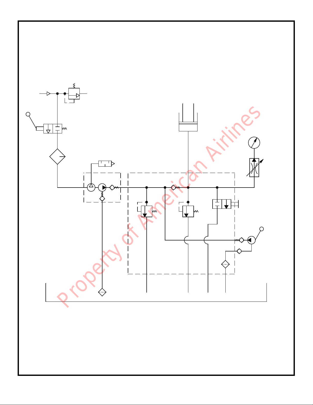
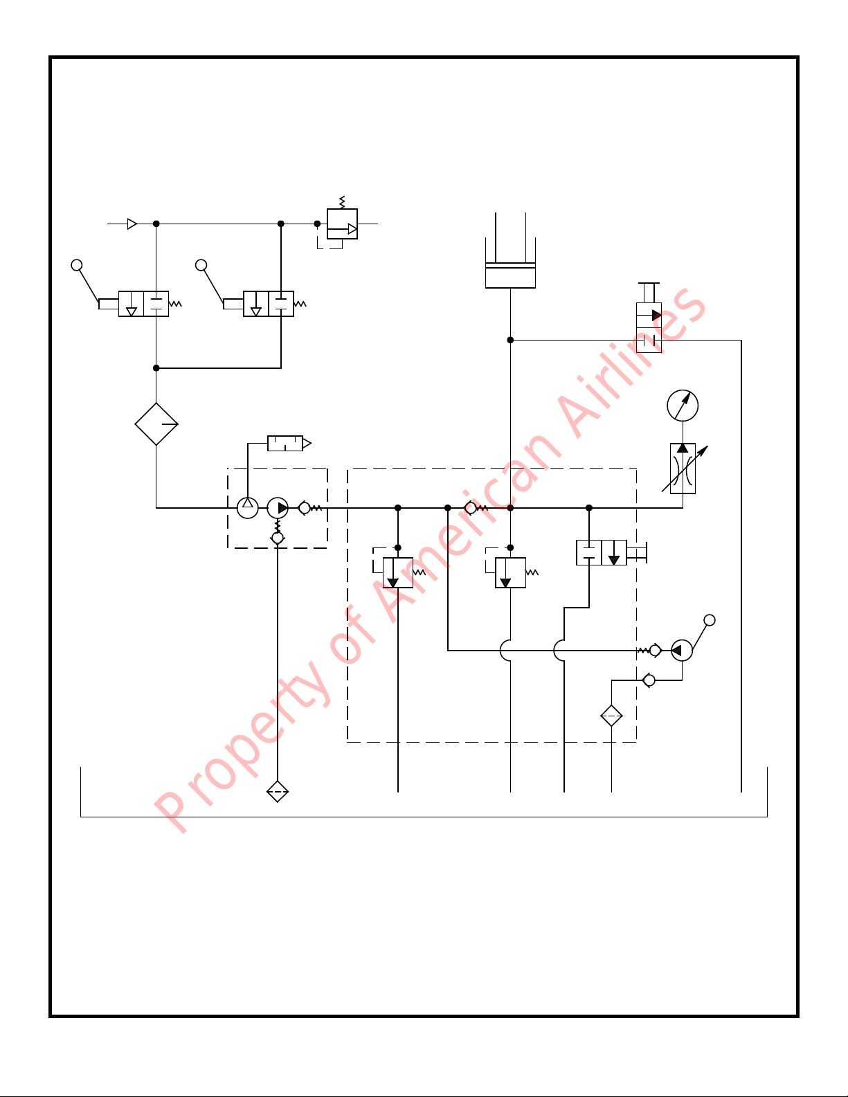
LOCATED IN THE HYDRAULIC CASTER VALVE BLOCK
ASSEMBLIES, SHOULD NOT BE REMOVED UNLESS ABSOLUTELY
NECESSARY. THE HYDRAULIC CASTER RELIEF VALVES ARE SET
TO BY-PASS HYDRAULIC FLUID BACK TO THE RESERVOIRS AT 900
± 20 psig (63.3 ± 1.4 kg/sq cm) IF ADJUSTMENT IS REQUIRED, SEE
PROCEDURE UNDER TESTING (SEE SHEET 5).
When necessary to disassemble the jack and/or the hydraulic casters (if so equipped), open all release
valves, drain all hydraulic fluid from reservoirs and carefully inspect the following:
1. Inspect interior walls of cylinders for smoothness and freedom from rust, nicks, scratches and
excessive wear.
2. Check plungers, extension screw, cylinders, tripod head, etc., for corrosion, wear and condition of
threads.
3. Verify that the extension screw has a positive stop to prevent it from being extended beyond its safe
thread engagement.
4. Inspect packings, seals, gaskets and wipers in the cylinder assembly, hand pumps and hydraulic
caster assemblies for cuts, scratches, deterioration and distortion.
5. Inspect upper and lower bearings for excessive scoring and/or wear.
6. Check oil screen located in the valve block for cleanliness.
7. Inspect valves and valve seats in the hand pump bodies and valve blocks for scratches, dents and
proper seating of the balls.
8. Inspect all pivot pins for wear, cracks, pits or evidence of damage or pending damage.
9. Check tripod structure for damages.
10. Inspect all areas for excessive dirt, oil, dust and chips.
REPAIR AND REPLACEMENT:
No definite time schedule can be established for the overhaul of the jack for replacement of the various
moving parts. The number of times the jack is raised and lowered and the amount of load raised at each
operation materially affect the life of the working parts. Do not overload the jack. Overloading is
dangerous, will hasten the need for overhaul and may damage the jack. During overhaul, replace all parts
that do not pass disassembly inspection requirements. Regardless of apparent condition, replace all parts
marked with (♦) and (✚) in the parts breakdown. A repair parts kit (P/N 795PK) which contains all of the
parts marked with (♦) and a hydraulic caster repair parts kit (P/N 8818PK) which contains all of the parts
marked with (✚) are available and recommended to keep on hand at your facility. Coat all O-rings and
back-up rings with hydraulic fluid MIL-H-5606 prior to assembly. Clean all metal parts with clean solvent
and dry with compressed air. Lubricate all threads. Use teflon tape carefully on all pipe threads. Remove
excess tape because it can clog valves and passages. If ball valves, located in valve blocks, do not seat
properly, they may need to be reseated by tapping the ball into the valve seat with a brass rod cupped at
one end.
TESTING:
Place jack in a load indicating test fixture. Make sure the test adapter is 1 1/4 inch female spherical
radius. Operate jack hand pump to extend plunger against the test adapter. Make sure ship adapter and
test adapter are correctly mated. Load test the jack at rated capacity of 100 tons. If the jack fails to
operate properly, check for trouble as indicated in the Trouble Shooting Chart (see sheet 12). With the
plunger extended and supporting the capacity load, allow the jack to stand for 10 minutes. Any excess
settling indicates leakage in the hand pump, check valves or jack packing seals. Check for hydraulic fluid
leaks and replace all defective parts.
If adjustment is required for the jack thermal relief valve, perform the following procedure:
1. Remove plug (figure 3, item 8) to expose thermal relief valve. Close release valve (figure 3, item 2).
2. Place jack in a load indicating test fixture. Make sure the test adapter is 1 1/4 inch female spherical
radius. Operate hand pump to extend plunger against the test adapter. Make sure ship adapter and
test adapter are correctly mated.
Property of American Airlines

- 6 -
3. While operating the hand pump, adjust set screw (figure 3, item 9) until the thermal relief valve by-
passes hydraulic fluid back to the reservoir at 120.0 to 125.0 tons.
4. Replace plug (figure 3, item 8). Once more operate hand pump to verify correct setting.
5. Open release valve to relieve pressure.
If adjustment is required for the jack system relief valve, perform the following procedure:
1. Remove plug (figure 3, item 8) to expose system relief valve. Close release valve (figure 3, item 2).
2. Place jack in a load indicating test fixture. Make sure the test adapter is 1 1/4 inch female spherical
radius. Operate hand pump to extend plunger against the test adapter.
3. While operating the hand pump, adjust set screw (figure 3, item 9) until the system relief valve by-
passes hydraulic fluid back to the reservoir at 105.0 to 110.0 tons.
4. Replace plug (figure 3, item 8). Once more operate hand pump to verify correct setting.
5. Open release valve to relieve pressure.
If adjustment is required for the hydraulic caster relief valves (if so equipped), perform the following
procedure:
1. Remove plug (figure 11, item 12) to expose relief valve. Close release valve (figure 11, item 6).
2. Remove plug (figure 11, item 33) and install a 0-1000 psig test gauge.
3. Operate the hydraulic caster hand pump (figure 11, item 17) to fully extend caster. Continue to
operate hand pump until the relief valve by-passes hydraulic fluid back to the reservoir at 900 ± 20
psig (63.3 ± 1.4 kg/sq cm).
4. Replace plug (figure 11, item 12). Once more operate hand pump to verify correct setting.
5. Open release valve to relieve pressure, remove test gauge and replace plug (figure 11, item 33).
6. Repeat for other hydraulic casters.
SPECIAL TOOLS:
The following special tools are necessary to disassemble/reassemble the cylinder assembly, the hydraulic
casters (if so equipped) and the shock absorber assembly (if so equipped). These tools may be
purchased upon request:
Part No. Description Qty
79588 Spanner wrench, retaining nut---------------------------------------------------------------------- 1
490-028 Spanner wrench, hydraulic caster cap------------------------------------------------------------ 1
78957 Lifting tool, extension screw ------------------------------------------------------------------------- 1
79589 Lifting tool, plunger------------------------------------------------------------------------------------- 1
78956 Lifting tool, tripod head-------------------------------------------------------------------------------- 1
78955 Lifting tool, cylinder------------------------------------------------------------------------------------- 1
872845 Accumulator test gauge assembly, 0-300 psig------------------------------------------------- 1
RECOMMENDED SPARE PARTS:
The following spare parts are recommended and available upon request.
Part No. Description Qty
Standard Spare Parts
795PK Repair parts kit ------------------------------------------------------------------------------------------ 1
56010-1 Valve block assembly --------------------------------------------------------------------------------- 1
79366 Release valve knob ------------------------------------------------------------------------------------ 1
79365 Release valve stem ------------------------------------------------------------------------------------ 1
65228 Release valve lockscrew ----------------------------------------------------------------------------- 1
55155 Safety pop-off valve assembly---------------------------------------------------------------------- 2
79571-1 Hand pump assembly --------------------------------------------------------------------------------- 1
55762-7 Pump handle--------------------------------------------------------------------------------------------- 1
76347 Reservoir gasket---------------------------------------------------------------------------------------- 1
79562 Filler cap with dipstick--------------------------------------------------------------------------------- 1
424-005 Drain cock valve ---------------------------------------------------------------------------------------- 1
Property of American Airlines

- 7 -
55991-14 Placard, tonnage, 100 ton---------------------------------------------------------------------------- 1
79596 Placard, instruction------------------------------------------------------------------------------------- 1
55998 Sticker, Malabar----------------------------------------------------------------------------------------- 2
55994 Sticker, fluid ---------------------------------------------------------------------------------------------- 1
75940 Sticker, towing------------------------------------------------------------------------------------------- 1
79536A Spring loaded swivel caster with swivel lock---------------------------------------------------- 3
79307 Lower bearing-------------------------------------------------------------------------------------------- 1
79619 Upper bearing-------------------------------------------------------------------------------------------- 1
79386 Ship adapter---------------------------------------------------------------------------------------------- 1
79595 Rain hat---------------------------------------------------------------------------------------------------- 1
Air Pump Kit Spare Parts
441-001 Air pump--------------------------------------------------------------------------------------------------- 1
441-030 Seal kit, air pump --------------------------------------------------------------------------------------- 1
421-004 Air valve --------------------------------------------------------------------------------------------------- 1
425-001 Air relief valve-------------------------------------------------------------------------------------------- 1
471-001 Lubricator ------------------------------------------------------------------------------------------------- 1
499-001 Muffler------------------------------------------------------------------------------------------------------ 1
481-001 Oil screen ------------------------------------------------------------------------------------------------- 1
Electric Motor - Hydraulic Pump Spare Parts
431-010 Electric motor -------------------------------------------------------------------------------------------- 1
440-055 Hydraulic gear pump----------------------------------------------------------------------------------- 1
432-020 Flexible coupling---------------------------------------------------------------------------------------- 1
Load Gauge Kit Spare Parts
79368 Load gauge----------------------------------------------------------------------------------------------- 1
424-001 Shutoff valve --------------------------------------------------------------------------------------------- 1
Adjustable Foot Kit Spare Parts
75941 Sticker, footpad------------------------------------------------------------------------------------------ 3
79225 Level assembly------------------------------------------------------------------------------------------ 1
Hydraulic Caster Kit Spare Parts
8818PK Hydraulic caster repair parts kit--------------------------------------------------------------------- 3
881802-1 Swivel caster--------------------------------------------------------------------------------------------- 1
881802-2 Swivel caster with swivel lock----------------------------------------------------------------------- 2
483-006 Breather --------------------------------------------------------------------------------------------------- 3
79366 Release valve Knob------------------------------------------------------------------------------------ 3
79365 Release valve stem ------------------------------------------------------------------------------------ 3
65228 Release valve lockscrew ----------------------------------------------------------------------------- 3
881816 Safety pop-off valve assembly---------------------------------------------------------------------- 3
Shock Absorber Kit Spare Parts
490-029 Shock Absorber ----------------------------------------------------------------------------------------- 3
MS28778-6 O-ring------------------------------------------------------------------------------------------------------- 6
Ladder Assembly Kit Spare Part
76378 Safety chain assembly -------------------------------------------------------------------------------- 1
Remote Control Kit Spare Parts
421-004 Air valve --------------------------------------------------------------------------------------------------- 1
85416 Release valve-------------------------------------------------------------------------------------------- 1
76158 Placard, caution----------------------------------------------------------------------------------------- 2
Property of American Airlines

- 8 -
PNEUMATIC / HYDRAULIC DIAGRAM
RESERVOIR
H
J
K
L
M
N
P
D
A
B
C
D
E
F
G
- AIR RELIEF VALVE
- AIR VALVE
- LUBRICATOR
- AIR PUMP
- MUFFLER
- OIL SCREEN
- VALVE BLOCK
F
G
H
C
AIR INLET
B
A
E
F
P
- SYSTEM RELIEF VALVE
- THERMAL RELIEF VALVE
- CYLINDER ASSEMBLY
- LOAD GAUGE
- SHUTOFF VALVE
- RELEASE VALVE
- HAND PUMP
JN
KL
M
Property of American Airlines

- 9 -
- AIR RELIEF VALVE
- AIR VALVE
- LUBRICATOR
- AIR PUMP
- MUFFLER
- OIL SCREEN
- VALVE BLOCK
H
RESERVOIR
PNEUMATIC / HYDRAULIC DIAGRAM
WITH REMOTE CONTROL
F
G
A
B
C
D
E
F
G
CE
D
A
AIR INLET
B B
JN
- SYSTEM RELIEF VALVE
- THERMAL RELIEF VALVE
- CYLINDER ASSEMBLY
- LOAD GAUGE
- SHUTOFF VALVE
- RELEASE VALVE
- HAND PUMP
P
F
H
J
K
L
M
N
P
M
K
L
N
Property of American Airlines

- MOTOR / PUMP ASSEMBLY
- HAND PUMP
- HYDRAULIC PUMP
- OIL SCREEN
- VALVE BLOCK
- SYSTEM RELIEF VALVE
- THERMAL RELIEF VALVE
RESERVOIR
-10 -
PNEUMATIC / HYDRAULIC DIAGRAM
WITH ELECTRIC MOTOR
E
A
B
C
D
E
F
G
C
A
N
F
M
B
D
H
J
K
L
M
N
- CYLINDER ASSEMBLY
- LOAD GAUGE
- SHUTOFF VALVE
- RELEASE VALVE
- ELECTRIC MOTOR
- COUPLING
GL
H
K
J
Property of American Airlines

RESERVOIR
-11 -
- CYLINDER ASSEMBLY
- RELEASE VALVE
- METERING ORIFICE
HYDRAULIC CASTER
HYDRAULIC DIAGRAM
F
A
D
E
F
A
B
C
- VALVE BLOCK
- HAND PUMP
- RELIEF VALVE
E
B
G - SHOCK ABSORBER
D
C
G
Property of American Airlines

PROBABLE CAUSE
Release valve open. (Oil
passing back into reservoir.)
Intake valve open. (Oil passing
back into reservoir.)
Discharge valve open. (Oil
passing back into pump
chamber.)
Sticking intake valve.
Clogged screen.
Lack of oil. Air under plunger.
Lack of oil.
Sticking intake valve.
High pressure leaks. (At pump
or release valve.)
Leaky release valve.
Leaky discharge valve.
Leaky release valve.
Defective "O" ring and back up
ring.
Damaged release valve.
Bent plunger.
Air under plunger.
Air in pump chamber.
Sticking intake valve.
Clogged screen.
Leaky intake valve.
Sticking intake valve.
Clogged screen.
TROUBLE
Jack will not raise.
Jack will not raise to full
height.
Jack will not raise capacity
load.
Jack raises and falls during
each stroke.
Jack will not hold up load.
Jack will not lower the load.
Jack will not close
completely.
Handle stroke only partly
effective.
Handle raises without effort.
Handle snaps back.
TROUBLE SHOOTING CHART
REMEDY
Close valve firmly.
Pump rapidly to flush dirt off.
Remove pump from jack base.
Unscrew valve block. Clean or
replace valve.
Remove and clean.
Refill. Check for leaks. Bleed
air out by opening release
valve. Pump rapidly a few
times and close release valve.
Refill, check for leaks.
Remove pump from jack base.
Unscrew valve block. Clean or
replace ball valves. Re-tighten
or repair.
Reseat valve.
Reseat valve and clean valve
block.
Tighten or replace ball valve or
packing.
Reseat valve.
Remove plunger and replace
"O" ring and back up ring.
Remove and replace parts as
needed.
Replace.
Bleed air out. Open release
valve and pump rapidly several
times. Close valve.
Open release valve and pump
rapidly several times. Close
valve.
Remove pump and clean valve
block.
Remove and clean.
Remove pump and clean valve
block.
Open release valve. Pump
rapidly several times. close
valve.
Remove and clean.
- 12 -
Property of American Airlines

FIGURE 1A
CYLINDER ASSEMBLY
RESERVOIR (NO R/C KIT)
TRIPOD HEAD PIN
RETAINING RING
VALVE BLOCK ASSEMBLY
SWIVEL CASTER
RESERVOIR STRAP
TOW HANDLE
SPACER
HHCS, 1/2-13 x 1 1/2 LG
HHCS, 1/2-13 x 1 3/4 LG
HHCS, 3/4-10 x 4" LG
FLAT WASHER, 1/2
SPLIT LOCKWASHER, 1/2
SPLIT LOCKWASHER, 3/4
HEX NUT, 1/2-13
HEX NUT, 3/4-10
ELBOW, 3/8 T x 3/8 SAE
TUBE, 3/8 O.D. x .065 WALL
19 A/R 732-010
20 2 55998
21 1 75940
22 1 717-008
23 1 717-003
24 1 78915
25 1 MS28778-6
26 1 79543
27 1 717-001
28 12 325-001
29 1 881802-1
30 2 881802-2
31 6 79507
32 1 79574
33 1 881818
34 1 78975
35 1 78990
36 1 79653
37 1 73148
NO. QTY PART NO. DESCRIPTION
MODEL 795 JACK ASSEMBLY
-13 -
1 1 79599
2 1 79391
3 3 79612
4 6 55923-200
5 1 56010-1
6 3 79536A
7 1 79557
8 1 79535
9 1 78985
10 4 321-014
11 12 321-006
12 1 321-010
13 14 362-005
14 16 363-004
15 1 363-006
16 14 351-003
17 1 351-004
18 1 722-018
19 A/R 732-010
NO. QTY PART NO. DESCRIPTION
27
9
10
13
14
19 18
25 ♦
TUBE, 3/8 O.D. x .065 WALL
STICKER, MALABER
STICKER, TOWING
PLUG, USED w/ NO AIR PUMP
AIR PUMP KIT
O-RING (PART OF ITEM 18)
ADJUSTABLE FOOT KIT
PLUG, USED w / NO GAUGE
FSHCS, 1/2-13 x 1 3/4 LG
SWIVEL CASTER
SWIVEL CASTER w/ LOCK
BRACE, USED w/ HYD. CAST.
ADJ. FOOT KIT w/ HYD. CAST.
SHOCK ABSORBER KIT
RESERVOIR (R/C KIT)
REMOTE CONTROL KIT
RESERVOIR (ELEC. MOTOR)
ELEC. MOTOR / PUMP KIT
11
13
14
16
6
7
24
10
14
16
23
5
36 2
34
22
20
55998
20
37
35
1
26
28
29
30
8
6 (REF)
12
15
17
♦PART OF REPAIR PARTS KIT
3
4
21
31
33
DRAIN
32
Property of American Airlines

20
MODEL 795 JACK ASSEMBLY
-14 -
BRACE
LOAD GAUGE KIT
RESERVOIR COVER
RESERVOIR GASKET
FILLER CAP w / DIPSTICK
DRAIN COCK VALVE
HHCS, 3/8-16 x 1 1/4 LG
HHCS, 1"-8 x 3 1/4 LG
FLAT WASHER, 3/8
SPLIT LOCKWASHER, 3/8
SPLIT LOCKWASHER, 1"
12 12 351-005
13 10 397-005
14 1 55994
15 1 79596
16 1 55991-14
17 1 79595
18 1 79225
19 1 79550
20 1 79567
21 1 79569
22 1 78567
NO. QTY PART NO. DESCRIPTION
FIGURE 1B
18
NO. QTY PART NO. DESCRIPTION
1 6 79552
2 1 79546
3 1 76346
4 1 76347
5 1 79562
6 1 424-005
7 6 321-008
8 12 321-002
9 6 361-001
10 6 363-003
11 12 363-008
22
21
HEX NUT, 1"-8
SELF TAPPING SCREW, #4
STICKER, FLUID
PLACARD, INSTRUCTION
PLACARD, TONNAGE, 100 TON
RAIN HAT (NOT SHOWN)
LEVEL ASSEMBLY
TRIPOD LEG
TRIPOD LEG w/ TOW BRKT
TRIPOD LEG w/ HANDLE HLDR
LADDER ASSEMBLY KIT
8
11
12
1
3
4
19
7
9
10
13
16
6
14
5
13
15
2
Property of American Airlines

79599 CYLINDER ASSEMBLY
FIGURE 2
CYLINDER
LOWER BEARING
PLUNGER
TRIPOD HEAD
UPPER BEARING
PLUNGER DIAPHRAGM
EXTENSION SCREW NUT
LOCKNUT ASSEMBLY
SHIP ADAPTER
RETAINING NUT
RETAINING RING
NO. QTY PART NO. DESCRIPTION
12 1 55925-446
13 1 55929-446
14 1 55932-266
15 1 55931-446
16 1 55925-438
17 1 55929-438
18 1 55928-700
19 1 371-014
20 1 331-001
21 1 331-002
22 1 79384
- 15 -
NO. QTY PART NO. DESCRIPTION
1 1 79503
2 1 79307
3 1 79306
4 1 79313
5 1 79619
6 1 79607
7 1 79316
8 1 79317
9 1 79386
10 1 79320
11 1 55924-825
♦13
♦12
2
18 6
O-RING
BACK-UP RING
O-RING
TEFLON O-RING W / GROOVE
O-RING
BACK-UP RING
RETAINING RING
ROLL PIN, 1/4 x 5/8 LG
SHSS, 1/2-20 x 1/2 LG
SHSS, 3/8-16 x 1/2 LG
EXTENSION SCREW
16 ♦
17 ♦
11 ♦
1
19
3
8
5
10
9
22
14 ♦
15 ♦
4
21
7
20
♦PART OF REPAIR
PARTS KIT
Property of American Airlines

11
56010-1 VALVE BLOCK ASSEMBLY
FIGURE 3
- 16 -
PLUG, FLUSH, 1/16 NPT
RELEASE VALVE KNOB
RELEASE VALVE STEM
BACK-UP RING
O-RING
STEEL BALL, 5/16 DIA
SETSCREW, 5/16-24 x 5/16 LG
PLUG, 1/4 SAE
SAFETY BYPASS SCREW
SPRING
SPRING GUIDE
STEEL BALL, 1/4 DIA
PLUG, 3/8 SAE
NO. QTY PART NO. DESCRIPTION
1 2 717-048
2 1 79366
3 1 79365
4 1 55929-011
5 1 55925-011
6 1 412-002
7 1 331-004
8 2 717-001
9 2 55148
10 2 55154H
11 2 55153
12 2 412-004
13 1 717-003
8
26 ♦
24
(SYSTEM RELIEF VALVE)
10 ♦
21
9
OIL SCREEN
ELBOW, 3/8 T x 3/8 SAE
SPRING
STEEL BALL, 3/8 DIA
O-RING
SHCS, 3/8-24 x 3" LG
PLUG, SOC HD, 1/16 NPT
VALVE BLOCK
HAND PUMP ASSY
RELEASE VALVE LOCKSCREW
SAFETY POP-OFF VALVE ASSY
O-RING (PART OF ITEM 13 &15)
O-RING (PART OF ITEM 8)
NO. QTY PART NO. DESCRIPTION
14 1 55568
15 1 722-018
16 1 79367
17 1 412-001
18 4 55925-014
19 4 323-009
20 1 717-010
21 1 76345
22 1 79571-1
23 1 65228
24 2 55155
25 2 MS28778-6
26 2 MS28778-4
19
20
14 ♦13
25 ♦
AIR PUMP PORT
19
♦18
♦5
♦4
2
73
1
12 ♦
♦6
23
♦18
♦18
22
1
25 ♦
17 ♦19
CYLINDER PORT
19
GAUGE PORT
16 ♦
♦PART OF REPAIR PARTS KIT
(THERMAL RELIEF VALVE)
24
♦12
♦10
11
8
♦26
9
15
Property of American Airlines

79571-1 HAND PUMP ASSEMBLY
13 1 55925-220
14 1 55761
15 1 55745
16 2 55927-43
17 1 55739
18 3 372-001
19 1 370-001
20 1 MS51861-44C
21 3 373-001
22 1 79563
23 1 55762-7
NO. QTY PART NO. DESCRIPTION
PISTON
O-RING
BACK-UP RING
SCRAPER RING
RETAINING RING
PUMP BODY
O-RING
STEEL BALL, 3/8 DIA
STEEL BALL, 5/16 DIA
SPRING
O-RING
PUMP CYLINDER NUT
- 17 -
FIGURE 4
NO. QTY PART NO. DESCRIPTION
1 1 55738
2 1 55925-213
3 2 55922-18
4 1 55728
5 1 55729
6 1 55753
7 1 55925-211
8 1 412-001
9 1 412-002
10 1 55754
11 1 55925-021
12 1 79564
♦16
♦10
♦9
♦18
♦21
♦7
♦13
12
6
8 ♦
11 ♦
16 ♦
O-RING
FULCRUM
PUMP HANDLE CLAMP
RETAINING RING
LINK
COTTER PIN, 3/32 x 3/4 LG
QUICK RELEASE PIN, 1/4 DIA
SELF TAPPING SCREW, #10
FLAT HEAD PIN, 7/16 DIA
CYLINDER
PUMP HANDLE
18 ♦
21 ♦
2 ♦
17
22
1
3 ♦
20
14
♦4
♦5
♦18
♦21
15
19
3 ♦
♦PART OF REPAIR PARTS KIT
23
Property of American Airlines

10
78915 AIR PUMP KIT
- 18 -
AIR PUMP
STUD
AIR VALVE
LUBRICATOR
MUFFLER
NIPPLE, BRASS, 1/2 x 3" LG
NIPPLE, BRASS, 1" x 4" LG
ELBOW, BRASS, 1" FPT
ELBOW, 1/2 T x 1/2 MPT
TEE, BRANCH, 1/2 NPT
ELBOW, 1/2 MPT x 3/8 FPT
REDUCER, 3/8 MPT x 1/4 FPT
AIR RELIEF VALVE
ALLEN NUT, 5/16-18
FIGURE 5
15 2 321-013
16 2 363-003
17 1 722-018
18 1 722-015
19 A/R 732-010
20 A/R 732-001
21 2 711-004
22 1 719-001
23 1 481-001
24 1 712-011
25 2 363-002
26 2 361-001
27 1 MS28778-6
NO. QTY PART NO. DESCRIPTIONNO. QTY PART NO. DESCRIPTION
1 1 441-001
2 2 392-001
3 1 421-004
4 1 471-001
5 1 499-001
6 1 711-006
7 1 711-016
8 1 712-015
9 2 722-013
10 1 713-021
11 1 712-032
12 1 714-009
13 1 425-001
14 2 359-001
13
11 12
15
16
26
18
19
17
♦27
HHCS, 3/8 - 24 x 1" LG
SPLIT LOCKWASHER, 3/8
ELBOW, 3/8 T x 3/8 SAE
ELBOW, 3/8 T x 1/2 MPT
TUBE, 3/8 O.D. x .065 WALL
TUBE, 1/2 O.D. x .049 WALL
NIPPLE, 1/2 MPT
SWIVEL ADAPTER
OIL SCREEN
ELBOW, STREET, 1/2 NPT
SPLIT LOCKWASHER, 5/16
FLAT WASHER, 3/8
O-RING (PART OF ITEM 17)
5
22
21
* 21
* 24
* 23
14
25
3
2
* PARTS ARE LOCATED INSIDE
RESERVOIR TANK
20
9
1
♦PART OF REPAIR PARTS KIT
94678
Property of American Airlines

22
12
13
FIGURE 6
73148 ELECTRIC MOTOR/PUMP KIT
-19-
10
29 94
30
8
8
10
30
FLOW
12
13
14
24
5
3
11
7
23
2
20
RESERVOIR (REF)
1
17
16
18
19
15
21
25
26
17
15
6
13
14
20
27
28
Property of American Airlines
Table of contents