Malloca THETA K1520 User manual

1
Please Read The User Manual Carefully!
CHIMNEY HOOD
USER’S MANUAL
INSTRUCTIONS FOR INSTALLATION
AND USE
THETA K1520
2
1. TECHNICAL DRAWING 3
2. WARNING AND SAFETY PRECAUTIONS 4
2.1 Life-Threatening Danger, Poisoning Danger 6
6
2.3 Danger of electric shock! 6
2. 4 Danger of physical injury! 6
2.5 Danger of burn, danger of electric shock! 7
7
3. USAGE WITH AND WITHOUT CARBON FILTER 8
3.1 Replacement of Carbon Filter 9
3.2 Replacement of Carbon Filter 9
3.3 AF 500 Carbon Filter 9
4. CLEANING AND PREVENTIVE MAINTENANCE 10
4.1 Washing in Dishwasher 10
4.2 Hand Wash 10
4.3 Removal/Installation of Aluminium Filter 10
5. INSTALLATION OF APPLIANCE 11
5.1 Installation and Unpacking of the Appliance 11
5.2 Installation and Unpacking of the Appliance 11
6. CONTENT OF PACKAGE 13
7. OVERVIEW OF COOKER HOOD 14
8. ASSEMBLY OF PRODUCT 15
8.1 Installation Template 15
8.2 Installation Diagram and Components 16
9. ASSEMBLY OF SHEET METAL FLUES 17
10 USE OF PRODUCT 18
10.1 3 Spd Touch Button 18
11. REPLACING THE LAMPS 19
11.1 Replacement of Halogen Lamp 19
11.2 Replacement of Spark Plug Lamp 19
12. AUTHORIZED SERVICE 20
12.1 Potential Failures and Solutions 21
12.2 Technical Table 21

3
1. TECHNICAL DRAWING
900
Fig. 1: TECHNICAL DRAWING

4
2. WARNING AND SAFETY PRECAUTIONS
■This appliance can be used by children
aged from 8 years and above and persons with
reduced physical, sensory or mental capabili-
ties or lack of experience and knowledge if they
have been given supervision or instruction con-
cerning use of the appliance in a safe way and
understand the hazards involved.
■This product is designed for home use.
■Usage voltage of your product is 220-240
Volt~50 Hz.
■ Power cord of your product is tted with a
grounded plug. This cord must be plugged into
a grounded outlet.
■The whole electrical wiring must be installed
by a qualied electrician.
■Installation by unauthorized persons could
lead to poor operation performance, damage to
the product, and accidents.
■Feeder cable of the appliance mustn't be ex-
posed to jamming or crashing during assembly.
Feeder cable mustn't be placed near the cook-
er. In such cases, it might melt down and lead
to re.
■Do not plug in the appliance before the in-
stallation.
■Make sure that the installation place allows
the user to easily unplug the power cable in
case of any danger.
■Do not touch your product's lamps when
they work for a long time. Since they would be
hot, they could burn your hand.
■Kitchen cooker hoods are designed for nor-
mal cooking and home use. For uses other than
specied, there is the risk of failure and the ap-
pliance becomes out of warranty.
■Comply with the regulations of the authori-
ties on the discharge of outlet air.
(This warning does not apply to uses without
ue.)
■Flammable foods must not be cooked under
the appliance.
■Turn on the appliance after placing a sauce-
pan, pan, etc. on the cooker. Otherwise, high
temperature might lead to deformation on some
components of your product.
■Turn off the cooker's burner before taking
the saucepan, pan, etc. off the cooker.
■Do not leave hot oil on your cooker. Pots
that contain hot oil might lead to inammation.
■ Since oils could catch re when you cook
fried foods in particular, be careful about your
curtains and tablecloths.
■ Ensure timely replacement of the lters. Fil-
ters not replaced in a timely manner pose risk
of re due to accumulated grease deposits on
them.
■ Do not use non-re-resistant ltering materi-
als instead of the lter.
■ Do not operate your product without lter,
and do not remove the lters when the product
is in use.
■ In case of any deagration, de-energize the
cooker hood and cooking appliances. (Plug off
the appliance or turn off the main switch).
■If your product's periodic cleaning is not
made in a timely manner, it could pose risk of
re.
■De-energize the appliance before any main-
tenance operations. (Plug off the appliance or
turn off the main switch.)
■When electric cooker hood and devices
fed with energies other than electricity operate
simultaneously, the negative pressure in the
room must not exceed 4 Pa ( 4 X 10 bar ).

5
■Gas or fuel oil burning appliances, such as
room heaters, which share the same environ-
ment with your product, must be fully insulated
from the exhaust of this product or they must be
hermetical.
■ When you make a ue connection for your
product, use pipes with a diameter of 150mm
or 120 mm.
■The length of the pipe connection as well as
the number of elbows must be as minimum as
possible.
■Children must not play with the appliance.
■For your safety, use ”MAX 6 A” fuse in the
cooker hood system.
■Since the packing materials could be dan-
gerous, keep them away from children.
■If the feeder cable is damaged, it must be
replaced by its manufacturer or authorized tech-
nical service or any other personnel qualied at
the same level, in order to avoid any dangerous
situation.
■ In case of any deagration, de-energize the
cooker hood and cooking appliances, and cov-
er the ame. Never use water to extinguish the
re.
■When cooking appliances are in operation,
their accessible parts could be hot.
■This appliance is not intended to be used
by people with physical, sensory and mental
disabilities (including children) or those who
have not adequate experience and knowledge
regarding its use, unless they are under the su-
pervision of a person responsible for the safety
of the appliance.
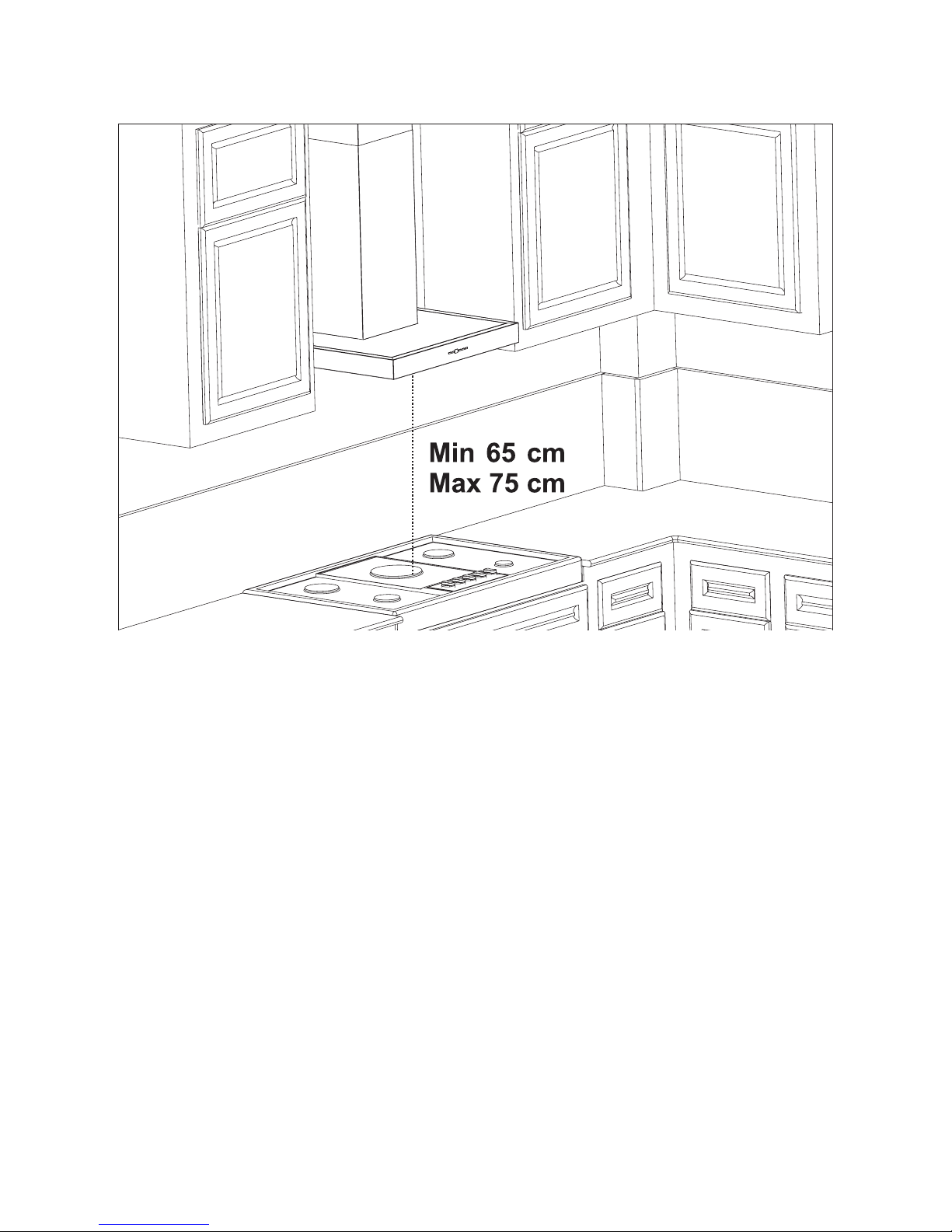
■After the installation of the cooker hood, the
minimum distance must be 65 cm between the
product and any electric cooker; and 75 cm be-
tween it and any gas ranges or cookers burning
other fuels.
■Output of the cooker hood must not be con-
nected to air ducts, where there exist another
smokes.
■You must be careful when using the appli-
ance spontaneously with other appliances (e.g.
gas, diesel fuels, coal or wood burning heaters,
shower heaters, etc.)
■Attention must be paid when using them
simultaneously. Because the cooker hood
could adversely affect the combustion, by
discharging the ambient air.
This warning does not apply to uses without
ue.
■When electric cooker hood is used simulta-
neously with devices that use gas or other fuels,
there must be sufcient ventilation in the room
(might not apply to devices that discharges the
air back into the room).
■Simultaneous operation of more than one
gas cooker leads to generation of high heat. A
ventilation appliance placed on the surface of
cookers might therefore get damaged or burn.
Do not operate two gas cookers in high heat for
more than 15 minutes. One large burner with
more than 5kW (Work) power generates power
equal to that of two gas burners.

6
2.1 Life-Threatening Danger, Poison-
ing Danger
DANGER
There are life-threatening danger and poisoning
danger due to reabsorbed combustion gases.
During the air discharge outlet use, unless suf-
cient air supply is provided, do not use the appli-
ance simultaneously with devices that discharge
toxic gases through ue such as ventilated, gas,
oil, wood or coal burning heaters, shower heat-
ers, water heaters, etc.
Fig. 2: Poisoning Danger
Ventilated devices (e.g. gas, oil, wood or coal
burning heaters, shower heaters, water heat-
ers) take combustion air from the installation
location, and discharge the waste gas through
a waste gas system (e.g. ue). When the cook-
er hood is active, it absorbs air from the kitchen
and neighbouring rooms. If adequate air entry is
not provided
vacuum emerges. In such a case, the toxic gas-
es are absorbed from the ue and waste gas
channel, and are taken into to door again. Fig. 2
Therefore, adequate fresh air ingress must al-
ways be ensured. Fig. 3
Fig. 3
DANGER
2.2 Risk of re!
Due to sparkling. Installation of appliance over
a heating device that is heated by using solid
fuels (for ex. wood or coal) is only allowed if an
non-detachable cover is present. For the instal-
lation process, attention must be paid to current
applicable construction regulations and regula-
tions of local electric and gas companies.
Appliance might lead to re unless it is produced
in accordance with cleaning instructions.
DANGER
2.3 Danger of electric shock!
Do not bend or jam the connection cable during
installation due to danger of damaged connec-
tion cable.
DANGER
2. 4 Danger of physical injury!
■During the installation, there is a danger
of physical injury due to the sharp edges. Use
protective gloves throughout the installation pro-
cess of the appliance.
■Due to risk of dropping the appliance, as-
sembly of all safety bolts and covers must be
performed as specied in the user manual.

7
2.5 Danger of burn, danger of elec-
tric
shock!
DANGER
■Allow the appliance to cool before cleaning or
maintenance process. Switch off the fuse or pull
out the mains plug from the socket.
■There is risk of damage due to ingress of mois-
ture in the electronics. Do not clean the control
components with a wet cloth.
■The surface could be damaged due to a wrong
cleaning process. Clean stainless steel surfac-
es only in their brushing direction. Do not use a
stainless steel cleaner for the control elements.
■The surface could be damaged due to aggres-
sive and abrasive cleaning agents. Never use
aggressive and abrasive cleaning agents.
■ There is risk of damage due to backow of
condensate. Mount the air outlet channel down-
wards from the appliance (slope of 1°).
DANGER
2.6 Dangers of re and physical
injury!
In case of repairing that is not performed accord-
ing to the rules or as required, turn off the fuse
or unplug the feeder cable of your appliance.
Repairing must be performed only by the autho-
rized technical service or authorized experts.
NOTE
If the appliance is faulty or damages, turn off the
fuse or unplug the feeder cable of your appliance
and call the authorized service.
NOTE
If the feeder cable is damaged, it must be
replaced by its manufacturer or its authorized
technical service or any other personnel
qualied at the same level, in order to avoid any
dangerous situation.
NOTE
If the bulbs of your appliance are faulty, turn
off the fuse or unplug the feeder cable of your
appliance. Replace the bulbs immediately to
avoid overload on other bulbs (wait for the bulbs
to cool down rst)
CAUTION
Accessible components might be heated when
used with cooking devices.
DANGER
Air outlet pipe of this appliance mustn't be con-
nected in the ue used to discharge the fume
generated by devices that use gas or other fuels.

8
You can use this appliance in exhaust air mode
and ventilated air mode.
Exhaust air mode
The absorbed air is cleaned by the grease lters,
and is discharged through a piping system. 4
Fig. 4: Air Outlet without Carbon Filter
WARNING
Death Risk!
Exhaust gases that are reabsorbed might lead to
poisoning.Exhaust air must not be transferred to
an active smoke or waste gas ue; or a ue used
for ventilation of the places, where heat sources
are installed.
■If you want to transfer exhaust air to an inac-
tive smoke or waste gas ue, you need to obtain
permission from an authorized chimney sweep.
■If exhaust air is discharged through the exter-
nal wall, a telescopic wall safe must be used.
Ventilated air mode
Absorbed air is cleaned by the grease lters and
an active carbon lter, and then it is transferred
back to the kitchen. 5
Fig. 5: Air Outlet with Carbon Filter
To retain the substances that lead to odour in
ventilated air mode, you must attach an active
carbon lter. Consult your authorized dealer for
various options available to use your appliance
in ventilated air mode. You can purchase the
accessories required for this process for related
sales points, authorized services or online sales
centre
3. USAGE WITH AND WITHOUT CARBON FILTER

9
3.1 Replacement of Carbon Filter
In environments without ue, active carbon lter
must be used for ltering the air and resending
it in. Active carbon lter must be supplied from
service or your dealer. De-energize the appli-
ance before replacing the carbon lter. Since
carbon lter is used in kitchens with no ue
outlet, it must be replaced in every 3-5 months
depending on the use.
Carbon lter must never be washed. Grease l-
ters must be installed in the product, regardless
of whether or not carbon lters are used. Do not
use your product without grease lter.
3.2 Replacement of Carbon Filter
Fig. 6: CARBON FILTER
The appliance you have purchased is
appropriate for use with carbon lters.
1. Place the carbon lter in its housing. Fig. 6
2. Rotating the carbon lter clockwise, ensure
that it is completely t. Fig. 6
3. If carbon lter does not t in completely, it
might drop and damage your product.
DANGER
Do not wash carbon lters. Keep the carbon l-
ters away from children.
3.3 AF 500 Carbon Filter
Fig. 7 AF 500 Carbon Filter
The appliance you have purchased is appropri-
ate for use with AF 500 carbon
lters.
• Place the lower part of the carbon lter to the
motor cabinet (Fig. 1).
• Press on the tab of the carbon lter and push it
forward, and ensure that the tabs of carbon lter
are engaged and locked (Fig. 1).

10
4. CLEANING AND PREVEN-
TIVE MAINTENANCE
CAUTION
■Prior to each maintenance and cleaning,
cooker hood must be unplugged, and appliance
must be dead
■Cleaning and user maintenance of the ap-
pliance shall not be performed by unattended
children.
■The surface could be damaged due to ag-
gressive and abrasive cleaning agents. Never
use aggressive and abrasive cleaning agents.
Supply your cleaning and protective substanc-
es that are appropriate for your appliance from
the authorized technical service. Surface of
appliance and control units are sensitive to
scratching.
■Clean the surfaces with a soft and damp
cloth, dish-washing liquid or mild glass cleaning
agent. Soften the dry, sticky dirt with a damp
cloth. Do not scrape!
■It is not appropriate to use dry cloths, sponges
that may scratch, materials that require rubbing,
and other aggressive cleaning agents contain-
ing sand, soda, acid or chlorine.
■Clean the stainless steel surfaces in their
brushing direction only.
■Do not use stainless steel cleaning agents
and wet clothes for control units. Cleaning of
metal grease lters Used metal grease lters
retain the greasy particles in the moisture and
vapour generated in the kitchen. Clean the met-
al grease lters about every three months, un-
der normal use conditions (1 to 2 hours a day).
■Do not use excessively effective, acidic or al-
kaline cleaning agents.
■ For cleaning the metal grease lters, clean
the holder parts of the metal grease lters in the
appliance, with a damp cloth as well.
■ You can clean the metal grease lters in the
dishwasher or by hand.
4.1 Washing in Dishwasher
■In case of washing in dishwasher, a slight
change might occur in colour. This has no effect
on the function of the metal grease lter.
■Do not wash the excessively dirty metal
grease lters together with dishes.
■ Place the metal grease lters loosely and
freely in the dishwasher. Metal grease lters
must be placed in the dishwasher without jam-
ming.
4.2 Hand Wash
For stubborn dirts, you can use a special
grease solvent. You can buy such an agent
from the authorized sales centre.
■ Soften the metal grease lters in a hot water
with dish-washing liquid.
■Use a brush for cleaning and wait for the liq-
uid in metal grease lters to ow off completely.
■ Rinse the lters thoroughly after cleaning.
CAUTION
Thanks to timely cleaning of metal grease lter,
the re danger caused by excessive heat that is
generated during frying is avoided.
4.3 Removal/Installation of Alumini-
um Filter
Pull the aluminium lter towards you by press-
ing on its tab. Reverse the process to install the
lter.
11
5. INSTALLATION OF APPLIANCE
Fig. 8: INSTALLATION OF APPLIANCE
After completing the installation of cooker hood, the minimum distance must be 650 mm between
the product and any electric cooker; and 750 mm between it and any gas ranges or cookers burning
other fuels. Fig. 8
5.1 Installation and Unpacking of
the Appliance
Check that your appliance is not deformed.
■Report the transport issues immediately to
transport operator.
■Any faults encountered shall be reported to
the dealer, too.
■Do not allow children to play the with packag-
ing materials !!!
5.2 Installation and Unpacking of the
Appliance
■ Replace the carbon lters on a regular basis.
■ Regularly clean your aluminium lters. Since
dirty lters would block the air passage, you
might have to use the appliance at a higher
speed.
■Use your product according to its normal
speeds.
■Use at higher speed would cause an increase
in the energy consumption.

12
5.3 Exhaust Air Mode
WARNING
Death Risk!
Exhaust gases that are reabsorbed might lead to
poisoning. Exhaust air must not be transferred to
an active smoke or waste gas ue; or a ue used
for ventilation of the places, where heat sources
are installed. If you want to transfer exhaust air
to an inactive smoke or waste gas ue, you need
to obtain permission from an authorized chim-
ney sweep.
If exhaust air is discharged over the external
wall,
a telescopic wall case must be used.
5.4 Air Discharge Line
Information: Manufacturer of appliance can-
not be held responsible for defects caused by
laid pipes.
■Appliance shows the highest performance
when a short and at air outlet pipe and a pipe
diameter as large as possible is used.
■Optimum ventilation performance cannot be
reached and noise of fan increases when long
and rough air outlet pipes and multiple pipe el-
bows or pipe diameters smaller than 150mm are
used.
■Pipes or hoses used in laying the air outlet
line must be made of inammable materials.
Circular Pipes
It is recommended that inner diameter should be
150 mm or at least 120 mm.
Flat Channels
Inner Section must be appropriate to the diame-
ter of circular pipes.
Ø150 mm approx. 177 cm²
Ø120 mm approx. 173 cm²
■Flat channels shouldn't have sharp elbows.
Use sealing strips for different pipe diameters.
5.5 Checking the Wall
Wall must be at, straight and have the sufcient
bearing capacity.
Depth of drilling holes must comply with the
length of bolts. Dowels must t in properly.
Bolts and dowels in the enclosure are appro-
priate for use in rigid monolithic walls. Use ap-
propriate fasting materials for different construc-
tions (for ex. plasterboard, aerated concrete,
proton bricks).
Maximum weight of your cooker hood is 40 Kg.
5.6 Electrical Connection
WARNING
Electric Shock Danger!
Components in the appliance might have sharp
edges. Connection cable can be damaged. Do
not bend or jam the connection cable during in-
stallation.
Necessary connection data is provided on the
type label found inside your appliance; metal
grease lters must be removed to see the label.
Length of connection line: approx.
1.3 m
This appliance complies with EU interference
elimination guidelines.
DANGER
5.7 Danger of Electric Shock!
It must always be possible to disconnect the
appliance from the electric network. Appliance
must be plugged in a protected contact outlet
that is mounted in accordance with the rules. If
the plug cannot be reached after installation or
during the required xed connection, there must
be many pole separation assemblies available
with at least 3 mm contact distance to the instal-
lation. Fixed connection must be performed by
an electronics expert only.
13
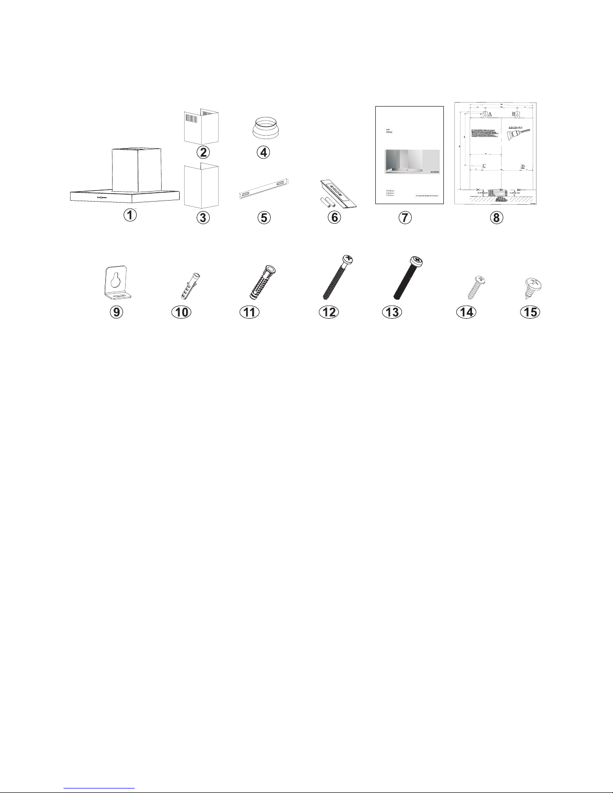
6. CONTENT OF PACKAGE
Fig. 9: CONTENT OF PACKAGE
1. Product
2. Inner Flue
3. Outer Flue
4. 150/120mm Plastic Flue
5. Flue Connection Plate
6. Remote Control (Optional)
7. User Manual
8. Assembly Pattern
9. Product Hanging Plate
10. Ø6mm Plastic Dowel
11. Ø 10 mm Plastic wall plug
12. 5.5x60 Wall Mount Screw
13. M5x35 Product Mount Screw
14. 3.9x22 Flue Connection Plate Screw
15. 3.5x9.5 Flue Connection Screw
14
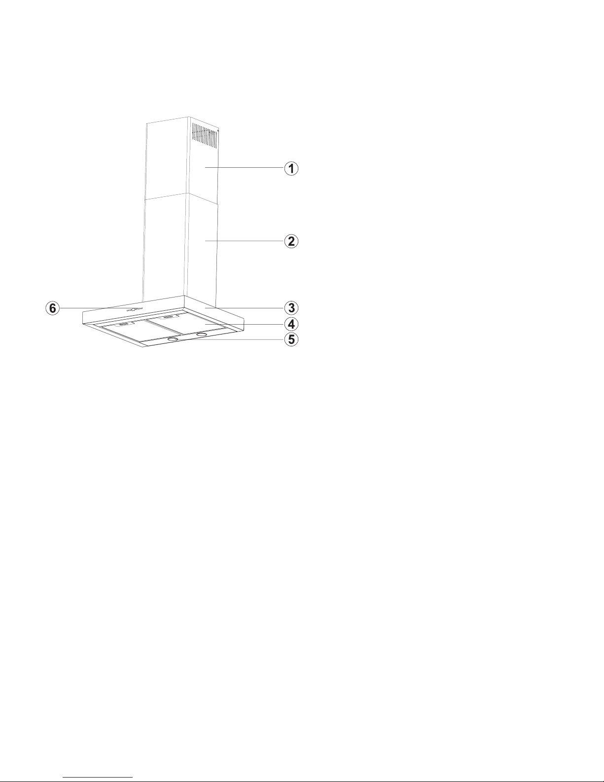
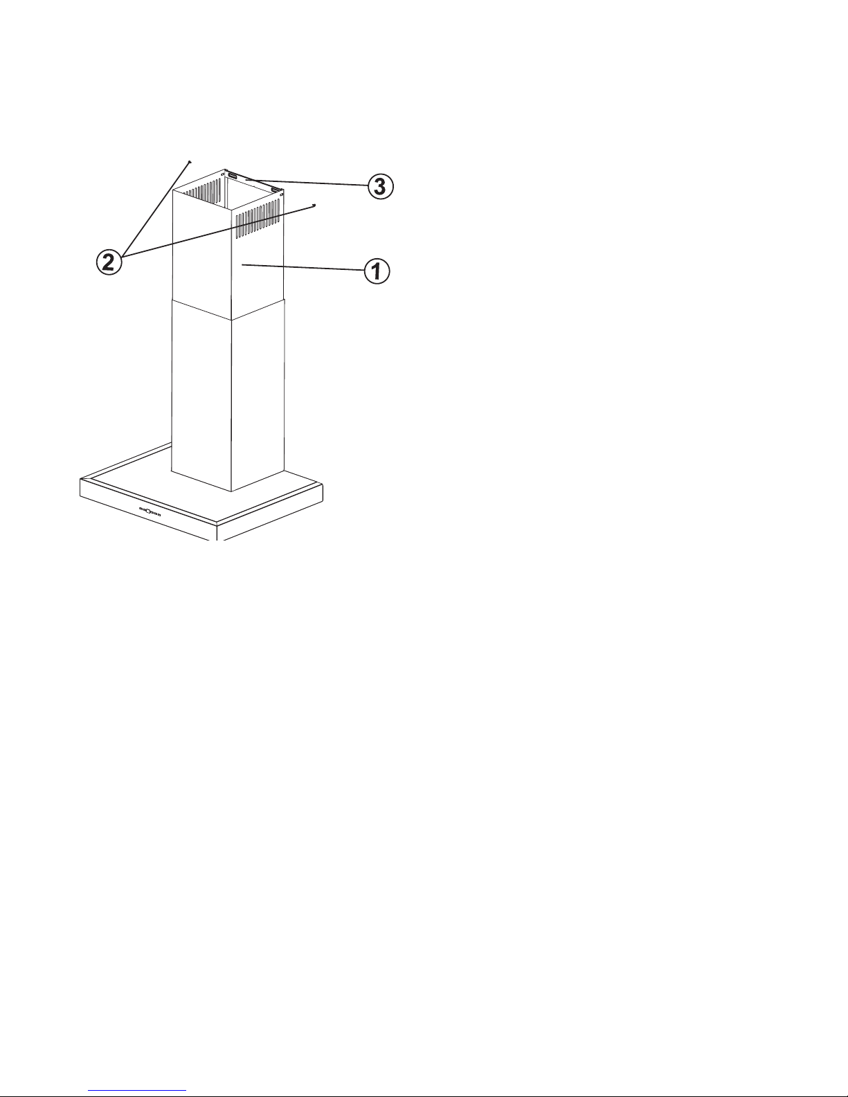
7. OVERVIEW OF COOKER
HOOD
Fig. 10: OVERVIEW OF COOKER HOOD
1. Inner Flue
2. Outer Flue
3. Front Panel
4. Filter
5. Cooker Lighting
6. Control Panel
15
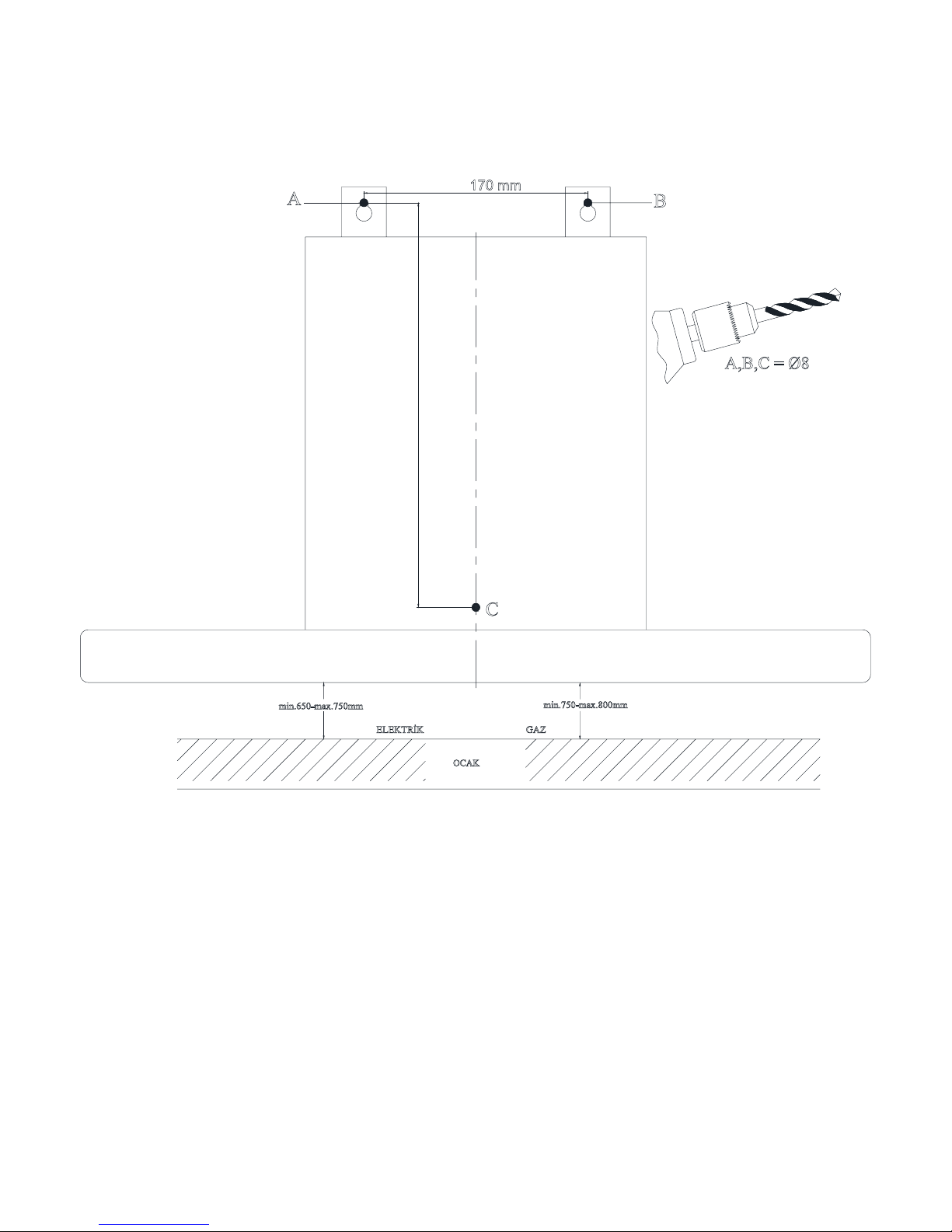
C
B
A
170 mm
A,B,C = Ø8
min.650-max.750mm min.750-max.800mm
OCAK
ELEKTRİK GAZ
307 mm
8. ASSEMBLY OF PRODUCT
8.1 Installation Template

16
8.2 Installation Diagram and Components
1. Inner Flue
2. Outer Flue
3. Product Hanging Plate
4. Product Hanging Plate Fixing Screw
5. Glass
6. 3x 5.5 x 60 Wall Mount Screw
7. 3x Ø 10 mm Plastic wall plug
8. 2x 3.9x22 Screw
9. Flue Connection Plate
10. 2x Ø6mm Plastic Dowel
■Perform the assembly of the cooker hood with
the help of the assembly scheme. (Fig. 8/8).
■ Afx the assembly pattern on the wall at the
specied height (See the minimum and maxi-
mum distances intended for the worktop, in the
assembly pattern) and drill holes A, B and C
with the dimensions specied in the template
(Fig. 11).
■Insert Ø 10 mm
wall plugs into the holes drilled as A, B and C,
and screw down the screws at the points A+B,
in such a way as to ensure a 5mm space be-
tween the screw head and the wall (Fig. 11).
■ Afx the hanging plate of the cooker hood on
the body of the cooker hood with M5x35 screw
(3) (Fig. 11/10).
■Hang the cooker hood from its hanging plates
on the wall at points (A, B). If the cooker hood
is not parallel, position its shape to parallel by
tightening or loosening M5x35 screw (3).
■ Tighten A + B xing screws on the wall, and
completely secure the product at point C.
■Make the air connections of the product.
Fig. 11: INSTALLATION OF THE HOOD
17
Fig. 12: ASSEMBLY OF PLATE FUELS
1.Inner Flue
2.Flue Connection Plate Fixing Screws
3.Flue Connection Plate
The outer and inner sheet metal ues are as-
sembled one within the other.
The cooker hood is set in the midst, and then
the ue connecting plate (3) is directly afxed to
the wall, under the cover or points E and F are
marked after performing a measurement. (Page
16 Fig.10)
Drill points E and F with Ø6mm drill bit, and in-
sert Ø6mm and plastic dowels. Insert the ue
connection plate with 3.9x22 screws (Page 16
Fig.10)
By pulling the inner ue (1) with screw (2) up-
wards and
left, screw it to the ue connection plate (3) on
the right and left (Fig.12).
9. ASSEMBLY OF SHEET METAL FLUES

18
10 USE OF PRODUCT
10.1 3 Spd Touch Button
Fig. 13: Touch Button
1. Press this button to turn on the product.
When this button is pressed, product will also
operate at speed level 1 (Fig.13).
2. When this button is pressed, product will op-
erate at speed level 2 (Fig.13).
3. Dgt Display: You can see the operation rate
of product on this screen (Fig.13).
4. When this button is pressed, product will op-
erate at speed level 3 (Fig.13).
5. Press this button to turn on or off the lamp
(Fig.13).
To activate timer function, press and hold any of
buttons 1, 2 and 3 for 3 seconds. Then, 15 min-
ute timer function will be activated and the prod-
uct will turn off automatically after 15 minutes.
All active functions operated prior to activation
of timer function will be deactivated after 15
minutes. All active functions operated after acti-
vation of timer function will be reactivated after
15 minutes.
NOTE
Programmable functions can be set when the
motor and lamp are turned off and timer isn't
set.
Back light brightness settings
When you press - button for approx. 5 seconds,
percentage of blue colour is displayed. (for ex:
B 00) Red colour percentage will appear on the
screen if - button is pressed one more time. (for
ex. R 100)
Green colour percentage may be displayed on
the screen by pressing . button one more time.
(for ex: G 10) By pressing on the colour and
buttons percentage of which is shown on the
screen (can be set faster by pressing longer),
percentage can be set between 0 and 100.
New colour is saved (a beep sound is heard)
by pressing and holding - button for 5 seconds,
and setting mode is turned off. To exit the set-
ting mode without saving, Mot/off or lamp but-
tons can be pressed.
Back light option
Back light is set to be constantly on when
shipped from the factory. If desired, back light
can be set to off when motor and lamp are
turned off and timer is not set (i.e. when the
cooker hood is not in use) by pressing and
holding + button for about 5 seconds (a beep
sound is heard). In order to set the back light
back to constantly on again, + button is pressed
for about 5 seconds.

19
Boost Ventilation Mode:
The model you have purchased has a boost
Boost Mode: When the product is switched
to maximum speed while it is operated, a ’b’
symbol shall be displayed on the screen.
Boost symbol indicates that (boost ventilation)
mode is active on the model. Product shall
operate for 7 minutes in this mode and ‘b’
this period. After 7 minutes, product shall
automatically switch down one speed level
and shall resume operation in the lower speed
level.
Note: It is not possible to use timer feature in
the boost mode.
11. REPLACING THE LAMPS
DANGER
Disconnect the electrical supply of the cooker
-
cause they could burn your hands when they
are hot.
11.1 Replacement of Halogen Lamp
Fig. 13: Replacement of Halogen
the faulty bulb and replace with a new one with
the same rating.Fig. 13
11.2 Replacement of Spark Plug
Lamp
Fig. 14: Replacement of Spark Plug Lamp
the faulty bulb and replace with a new one with
the same rating.Fig. 14

20
12. AUTHORIZED SERVICE
If Lighting is Not Functioning:
■Make sure that the plug is plugged in, and that the fuses are intact.
■Check the bulbs. Make sure you unplugged the device before performing this check. Tighten the
bulbs if they are loose; you can replace the bulbs if they still don't work.
Possible Faults and What-to-Do Before
Calling the Technical Service:
A) If the appliance does not work in any way:
■
■Check the fuse, to which the appliance is connected, as well as the main fuse of your house.
or it operates with too much noise:
■
■
■
months.
■
Table of contents
Other Malloca Ventilation Hood manuals

Malloca
Malloca SLIM K1522 User manual

Malloca
Malloca MIN F-205 User manual

Malloca
Malloca HIH-864 User manual

Malloca
Malloca Space MH 900SP User manual

Malloca
Malloca MH 750BI User manual

Malloca
Malloca DRIVE F-152 User manual

Malloca
Malloca MC 9082 ISLAND User manual

Malloca
Malloca K-3410DR User manual

Malloca
Malloca MOV-656 ECO User manual

Malloca
Malloca K1153 User manual


