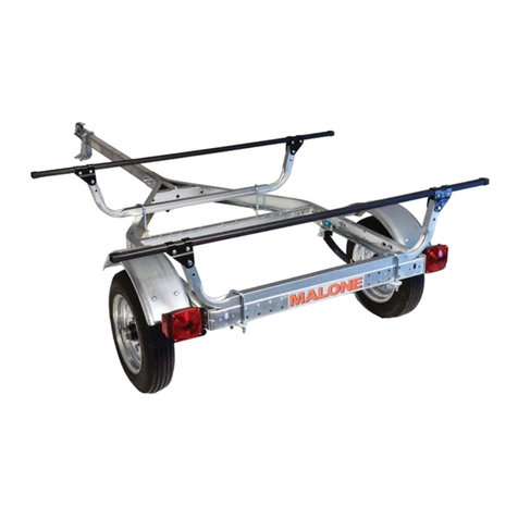
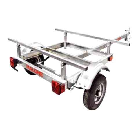
Malone XtraLight MPG525G User manual

*ATTENTION CUSTOMERS*
Thank you for your recent purchase of a Malone trailer.
Please inspect all parts and hardware bags prior to assembly.
**Set the large red envelope (in the axle box) containing important
documents pertaining to registering your trailer in a safe spot.
If you encounter any missing components please contact us at:
Email:[email protected]
OR
Phone:(207) 774 - 9100 X215
Business Hours: Monday-Friday
9am- 5pm
Thank you from all of us at Malone
MPG525
MALONE
R
MALONE
R

Important Note
Product Warranty & Registration Form
All information is condential and used exclusively by MALONE only.
MALONE
R
Dear Customer,
Thank you for your purchase of a Malone Product.
In order to be eligible for the Malone Warranty program, we ask that you contact us by email or
online at one of the following: With-in 30 days of purchase. You can also mail this letter back to the address at
the bottom.
• Online: www.maloneautoracks.com
We will require the information below.
Here is the information collected:
First Name:
Last Name:
Address:
Address2:
City:
State:
Zip:
Country:
Email:
Phone:
Product Description/Name:
Product MPG# or Serial #
Date Purchased:
Store Where Purchased:
Purchase Price:
Thank you for choosing Malone!
81 County Rd. Ste 1, Westbrook, ME 04092
P: 207.774.9100 F: 207.615.0551
E: sales@maloneautoracks.com W: www.maloneautoracks.com

800-295-0042 ext 206
MPG460XT
Take a few moments and read through these instructions to familiarize yourself
with the step by step assembly process before you begin turning wrenches.
Unpack and sort the components into groups as shown in the following pages.
Then assemble each group in order. Lets get started !!
Required Tools:
• (2) 3/4” wrenches • (2) 9/16” wrenches (a deep socket is recommended)
• Large flat blade screw driver • (1) 7/16” wrench
• Razor knife • Pliers
• Wire stripping tool • Electrical connector crimping tool
• Lug wrench • Small hammer
Visit us at maloneautoracks.com
for more fine products and accessories.
Malone MicroSport Trailer
Model MPG460XT Assembly Instructions
TM
REV 2
MPG525G
Malone XtraLightTM Trailer
Model MPG525G Assembly Instructions
Take a few moments and read through these instructions to familiarize yourself with the
step by step assembly process before you begin turning wrenches.
Unpack and sort the components into groups as shown in the following pages.
Then assemble each group in order. Lets get started !!
Required Tools:
• (2) 3/4” wrenches • (2) 9/16” wrenches (a deep socket is recommended)
• Large at blade screw driver • 7/16” wrench • 3/8” wrench and socket
• Large Phillips head screw driver • Rubber hammer
MALONE
R
MALONE
R
800-295-0042 ext. 215 1

MPG525G
Group 1:
Frame
Components
Bag 11430
Group 2:
Axle / Spring Components Bag 11432
Visit www.maloneautoracks.com/Replacement-Parts
for all of your spare part needs

800-295-0042 ext 206
MPG525G
Group 4: Fender Components
Bag 11431
Group 3:
Lighting
Components
Group 5: Coupler Components
Bag 11494
Group 3: Lighting Components
Bag 11468
800-295-0042 ext 206
MPG460G
1. Installing the ground wire con-
nector. Strip 3/8” of insulation off the
white ground wire and crimp on the
ring connector as shown.
2. Assemble the tongue skid and safety chain assembly
with a 3/8” x 1-1/2” bolt as shown. Use washers above
and below the chain ends.
COUPLER ASSEMBLY
(Group 5)
Visit www.maloneautoracks.com/Replacement-Parts
for all of your spare part needs

MPG525G
800-295-0042 ext 206
4
FRAME ASSEMBLY (Group 1)
Group 6:
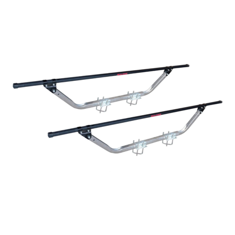
Load Bar
Components
Bag 11433
2. Get the wiring harness out of the
light kit. Un-kink the last 6 feet of
the 20 foot harness. Un-kink the
entire 4 foot harness. Wrap the 2
ends of the long harness together
with electrical tape.
4. Pass the entire harness through the grommet and out the top of
the tongue as shown.
3. Stand the front tongue section
on end with the coupler holes up.
Push a wire protection grommet
into the wiring harness hole as
shown.
1. First we will build the 2 piece tongue. The middle of the
tongue has symmetrical holes for the joining plates. The
forward end of the tongue has holes for the coupler.
D-Rings (4)
Load Bars (2) and Brackets (4)
Load Bars Support Tubes (4)
TONGUE & FRAME ASSEMBLY (Group 1)
1. First we will build the 2 piece tongue. The middle
of the tongue has symmetrical holes for the joining
plates, and You can identify the hitch end of the
tongue by the 3 holes on the left (drivers) side for
the coupler.
2. Align the tongue half’s together and insert the
wiring harness through both sections of the tongue,
making sure the plug end matches the
vehicles connection. The colored pigtails should
be towards the rear of the tongue.
MPG525G
800-295-0042 ext 206
6
14. Being careful not to pinch the wiring harness, square
the tongue half ends together and install the joining plates
on each side. (Note
the rear tongue section
is symmetrical so it
works fine either way.
It has no top and
bottom.) Fully tighten
the 1/2” bolts with two
3/4” wrenches.
NOTE: We begin assembling the frame upside down, later we will flip it over to complete the assembly.
15. Layout the frame components as shown, “upside down”.
(a) The spring bracket mounting holes in the side rails must face up.
(b) The tongue mounting holes in the middle of the front two cross members must face up.
(c) The MALONE decal is on the rear cross member and must be upside down.
(d) The mid-cross member must face the same way as the rear cross member.
(e) Spring hangers with shackle bolt holes to the front, slippers to the back.
(f) Carriage bolts to mount cross members to rails.
(g) Regular bolts to mount spring hanger brackets.
a
a
a
a
b
b
c
d
d
e
e
gf
16. Install all 12 carriage bolts, finger tighten only. Install all 8 spring hanger bolts with the nuts
inside the frame. Fully tighten the rear spring hangers. Finger tighten the front spring hangers.
4 800-295-0042 ext. 215
3. Being careful not to pinch the wiring harness,
square the tongue half ends together and install the
joining plates on each side. (Note the rear tongue
section is symmetrical so it works ne either way. It
has no top and bottom.) Fully tighten the 1/2” bolts
with two 3/4” wrenches.
Group 6: Load Bar Components
Coupler / Hitch End
Visit www.maloneautoracks.com/Replacement-Parts
for all of your spare part needs

MPG525G
800-295-0042 ext 206
6
14. Being careful not to pinch the wiring harness, square
the tongue half ends together and install the joining plates
on each side. (Note
the rear tongue section
is symmetrical so it
works fine either way.
It has no top and
bottom.) Fully tighten
the 1/2” bolts with two
3/4” wrenches.
NOTE: We begin assembling the frame upside down, later we will flip it over to complete the assembly.
15. Layout the frame components as shown, “upside down”.
(a) The spring bracket mounting holes in the side rails must face up.
(b) The tongue mounting holes in the middle of the front two cross members must face up.
(c) The MALONE decal is on the rear cross member and must be upside down.
(d) The mid-cross member must face the same way as the rear cross member.
(e) Spring hangers with shackle bolt holes to the front, slippers to the back.
(f) Carriage bolts to mount cross members to rails.
(g) Regular bolts to mount spring hanger brackets.
a
a
a
a
b
b
c
d
d
e
e
gf
16. Install all 12 carriage bolts, finger tighten only. Install all 8 spring hanger bolts with the nuts
inside the frame. Fully tighten the rear spring hangers. Finger tighten the front spring hangers.
MALONE
R
800-295-0042 ext. 215 5
4. Layout the frame components as shown, “upside down”.
(a) The spring bracket mounting holes in the side rails must face up.
(b) The tongue mounting holes in the middle of the front two cross members must face up.
(c) The MALONE decal is on the rear cross member and must be upside down.
(d) The mid-cross member must face the same way as the rear cross member.
(e) Spring hangers with shackle bolt holes to the front, slippers to the back.
(f) Carriage bolts to mount cross members to rails.
(g) Regular bolts to mount spring hanger brackets.
5. Install all 12 carriage bolts, nger tighten only. Install all 8 spring hanger bolts with the nuts inside the
frame. Fully tighten the rear spring hangers. Finger tighten the front spring hangers.
6. Lay the tongue onto the
frame, with the MALONE
logo upside down.
Support the end of the
tongue so it lays nearly
at on the front and mid
cross members.

800-295-0042 ext 206
MPG525G
17. Lay the tongue onto the frame, with the MALONE logo upside down. Support
the end of the tongue so it lays nearly flat on the front and mid cross members.
18. Install the long 1/2” bolt through the front cross member, (washer under the bolt head), nut inside
the cross member
and finger tighten.
Install the short 1/2”
bolt inside the end of
the tongue, (washer
under the bolt head),
nut inside the cross
member and finger
tighten.
19. Fully tighten all
12 carriage bolts.
Then fully tighten
the two 1/2” tongue
mounting bolts.
SPRING AND AXLE ASSEMBLY
(Group 2)
1. Set the envelope containing the manufacturer’s certificate of
origin (MCO) and VIN labels aside in a safe place.
2. Find the side of the axle
with the spring centering
holes. These holes mate
with the spring center stud.
4. Run each nut down UNTIL IT NEARLY TOUCHES
THE PLATE ONLY! DON’T FULLY TIGHTEN NOW!!
You may need to wiggle the springs to fit them into the
spring brackets in the next step.
7. Install the long 1/2” bolt through the front cross member, (washer under the bolt head), nut inside the
cross member and nger tighten. Install the short 1/2” bolt inside the end of the tongue, (washer under the
bolt head), nut inside the cross member and nger tighten
8. Fully tighten all 12 carriage bolts. Then fully tighten the two 1/2” tongue mounting bolts.
6 800-295-0042 ext. 215
MALONE
R
SPRING & AXLE ASSEMBLY (Group 2)

MPG525G
5. Lift the axle/spring assembly to the trailer frame and slide the slipper spring ends into the slipper
spring brackets. Then let the spring eyes down into the front hangers.
6. Install the shackle bolts with the nuts to the inside and
tighten until firm. Do not over tighten which would bend
the spring hanger in and pinch the spring.
7. Fully tighten the 4 front spring hanger mounting bolts.
8. Fully and evenly tighten the 8 axle U-bolts.
10. Lift the trailer at one rear corner
and roll it over onto the tires.
ALWAYS BEND FROM YOUR KNEES
WHEN LIFTING. IF THE TRAILER
IS TOO HEAVY FOR YOU TO FLIP
SAFELY RECRUIT SOME FRIENDS
TO ASSIST YOU.
11. Tighten the lug nuts firmly, to 75 to
85 foot pounds of torque.
9. Install the wheels on the hubs with
valve stems facing out and install and
finger tighten the lug nuts.
MPG525G
800-295-0042 ext 206
8
5. Lift the axle/spring assembly to the trailer frame and slide the slipper spring ends into the slipper
spring brackets. Then let the spring eyes down into the front hangers.
6. Install the shackle bolts with the nuts to the inside and
tighten until firm. Do not over tighten which would bend
the spring hanger in and pinch the spring.
7. Fully tighten the 4 front spring hanger mounting bolts.
8. Fully and evenly tighten the 8 axle U-bolts.
10. Lift the trailer at one rear corner
and roll it over onto the tires.
ALWAYS BEND FROM YOUR KNEES
WHEN LIFTING. IF THE TRAILER
IS TOO HEAVY FOR YOU TO FLIP
SAFELY RECRUIT SOME FRIENDS
TO ASSIST YOU.
11. Tighten the lug nuts firmly, to 75 to
85 foot pounds of torque.
9. Install the wheels on the hubs with
valve stems facing out and install and
finger tighten the lug nuts.
MALONE
R
800-295-0042 ext. 215 7

800-295-0042 ext 206
MPG525G
LIGHT ASSEMBLY (Group 3)
REFERENCE:
Trailer Wiring Color Code
•Brown = running lights
•Yellow = driver turn / driver brake
•Green = passenger turn / passenger brake
•White = ground
1. Sandwich the license plate mounting bracket
between the driver side lamp and the frame. Use the nuts
provided with the lamp kit.
3. Check that the wiring harness outside
the tongue grommet at the coupler is still
full length and did not pull into the tongue.
4. Route the GREEN/BROWN wire along
the passenger’s side of the frame. Route the
YELLOW/BROWN wire along the driver’s side. Install wire
clips beside the tongue and clip the wires.
5. Route each harness around the
corner to the side marker light. Note
where you will connect the side marker
wire. Lift the harness on top of the
frame. Pierce the knife tip between the
wires, PULL only about 1/2” of wire past
the blade, then use your fingers to pull
2-3 inches of wire apart.
2. Install side marker lights at the 2 holes in the front of the side
rails. One hole for the bolt, one hole for the
wire. Use the nuts provided with the lamp kit.
6. Press the brown wire into the quick connector as shown. Then
insert the wire from the side marker
light fully into the 2nd opening. Use
pliers to squeeze the conductor blade
down and through the insulation. The
blade cuts through the insulation and
connects the wires inside. Flip the
cover to lock the connector. Repeat on
the other side again using the brown
wire.
L.E.D. REFERENCE:
Trailer Wiring Color Code
•Brown = running lights
•Yellow = left turn / left brake
•Green = right turn / right brake
•White = ground
LIGHT ASSEMBLY (Group 3)
1. Sandwich the license plate mounting bracket between the driver
side lamp and the frame. Push the wire leads through the center
hole and the lamp studs through the outer holes. Use the nuts
provided with the lamp kit.
2. Using the holes in the front corners
of the frames side rail, mount the amber
side lights. First, push the wire leads
through the outside holes and the lamp
stud through the center hole.
3. Secure with the lamp stud nut.
8 800-295-0042 ext. 215
MALONE
R
4. Starting at the end of the tongue, we will divide the wiring to both sides of the trailer and then again to the
running lights and the tail lights.
Looking at the end connections, route the GREEN/BROWN/WHITE wire along the passengers side. Route
the YELLOW/BROWN/WHITE along the drivers side as shown. These color coated wires should match the
connections at your lights.
5. With the wiring divided at the end of the tongue, use the
clips provided to secure the wire to the inside of the frame
channel as shown.

MPG525G
800-295-0042 ext 206
10
7. Route the wires to the rear, through the middle cross
member and along the frame. Install wire clips to secure
the wires between the cross members.
9. Using your fingers, separate
about 1” of the ends of the
harness. Strip about 3/8” of
insulation off each wire to allow length for wrapping
around the stiff tail light wire.
8. Route the harness around
the corner and allow the same
length harness as the length
of the tail light wires. Triple
check that the wires are routed
where you want them. Cut the
harness.
10. Hold the color matching harness and tail light wires
together with the end of the stripped insulation even with
each other, then wrap the harness
wire clockwise around the tail lamp
wire completely covering it.
11. Screw a wire nut down over
each until firm. Then tuck the wire
into a frame clip as shown.
FENDER ASSEMBLY (Group 4)
1. Loosely install fender
mounting brackets as shown
so they can move to fit the
fender. Use hex bolts with
the nuts inside the frame.
2. Install and fully tighten
fender. Use screws and nuts,
nuts inside fender.
3. Fully tighten fender mounting brackets.
FENDER ASSEMBLY (Group 4)
6. Next, we’ll divide the wiring again. Direct the two(2) pigtailed end
towards the side running lights up front along the frame, and then the
three(3) pigtailed end towards the rear tail lights.
7. Route the wires to the rear, through the middle cross member and
along the frame. Install wire clips to secure the wires between the
cross members. Repeat on the other side of the trailer.
8. With the wires routed all the
lights, rmly grasp the wiring
connections and plug-in matching
colored leads/wires.
Repeat with all remaining lights.
MALONE
R
800-295-0042 ext. 215 9

COUPLER ASSEMBLY (Group 5)
1. Assemble the tongue skid and safety chain assembly with a 3/8” x 1-1/2” bolt as shown. Use washers
above and below the chain ends.
2. Place the skid and chain assembly under the tongue and insert the bolt up through the skid bolt hole on
the bottom of the tongue as shown.
3. Slip the nylon lock nut over the bolt and hand tighten.
4. Check that the rear end of the skid is still in its hole in the bottom of the tongue. Fully tighten the bolt and
lock nut.
5. Install the coupler and coupler handle onto the tongue as shown. Then tighten until the coupler rmly grips
the tongue. Don’t over tighten and crush the tongue.
NOTE: OVER TIGHTENING WILL PREVENT THE
COUPLER LATCH FROM FUNCTIONING PROPERLY.
800-295-0042 ext 206
MPG460G
1. Installing the ground wire con-
nector. Strip 3/8” of insulation off the
white ground wire and crimp on the
ring connector as shown.
2. Assemble the tongue skid and safety chain assembly
with a 3/8” x 1-1/2” bolt as shown. Use washers above
and below the chain ends.
COUPLER ASSEMBLY
(Group 5)
LOAD BAR ASSEMBLY (Group 6)
1. Use a small hammer or block of wood to install the
end plugs into both ends of all four load bar support
tubes.
2. Install the load bar support tubes onto the outer most
pair of holes in the front and rear cross member and
fully tighten.
MPG525G
800-295-0042 ext 206
12
2. Use a small hammer or block of wood
to install the end plugs into both ends of all
four load bar support tubes.
3. Install the load bar support tubes onto
the outer most pair of holes in the front
and rear cross member and fully tighten.
4. Install the load bars and brackets onto the load bar
supports. Center the load bars and fully tighten all load
bar bolts.
5. Use a small hammer or block of wood to install the
end caps onto the load bars.
Apply the TIRE AND LOADING Decal and the VIN Decal as shown below onto the driver side
of the frame. Be sure to clean the frame before applying the decals.
Visit us at maloneautoracks.com
for more fine products and accessories.
Your XtraLight Trailer is now complete and ready to register and title !
Contact your local DMV office for specific procedures in your State.
TM
10 800-295-0042 ext. 215
MALONE
R

MPG525G
800-295-0042 ext 206
12
2. Use a small hammer or block of wood
to install the end plugs into both ends of all
four load bar support tubes.
3. Install the load bar support tubes onto
the outer most pair of holes in the front
and rear cross member and fully tighten.
4. Install the load bars and brackets onto the load bar
supports. Center the load bars and fully tighten all load
bar bolts.
5. Use a small hammer or block of wood to install the
end caps onto the load bars.
Apply the TIRE AND LOADING Decal and the VIN Decal as shown below onto the driver side
of the frame. Be sure to clean the frame before applying the decals.
Visit us at maloneautoracks.com
for more fine products and accessories.
Your XtraLight Trailer is now complete and ready to register and title !
Contact your local DMV office for specific procedures in your State.
TM


MALONE
R
MALONE
R
Trailer Checklist & Maintenance Manual
MPG460G MicroSport
MPG535G MegaSport
MPG525G XtraLight
MPG570G Sherpa


Congratulations on your new Malone trailer!
Take a couple minutes to read through this manual for commonly asked questions and
some basic trailer maintenance that will ensure your trailer is preforming at its best.
And as always please free to contact us with any questions you may have.
ank you for choosing Malone.
Basic Trailering Checklist:
Before hitting the road for your next trip be sure to check the following.
~ Coupler, hitch and hitch ball are all the same size
~ Coupler and safety chains are safely secured to hitch of tow vehicle
~ All fasteners are properly tightened
~ Boat is securely tied down to trailer ( a winch line IS NOT a tie down)
~ Wheel Lug Nuts are properly tightened
~ Wheel bearing are properly adjusted and maintained
~ Load is within maximum load carrying capacity
~ Tires are properly inated
~ All trailer lighting is working properly
Additional checks you can do.
Conduct routine maintenance by having a friend or family member occasionally stand behind your
trailer and make sure the brake lights, taillights and turn signals are in good working order. As with
your boat, a thorough freshwater wash down of your trailer aer each use will extend the life of your
hubs and lights. It’s also a great boat maintenance idea to invest in a spare wheel, just in case.
Trailer hubs and lights can potentially get dunked twice every time you go boating. You need to
pamper them as you would your boat - this is an essential element of boat trailer maintenance.
Do an occasional hub inspection by popping o the cap with a screwdriver. If the bearings are dry,
add grease. It’s simple. Lets jump to the next page for a detailed step by step.
Be sure to review the table on the next page for trailer FAQs’ and specications.

XtraLight MicroSport MegaSport Sherpa
197 LBS (BASE "G")
230 LBS (XT)
260 LBS (LOWBED) 425 LBS (LOWBED)
LENGTH 11' 2" 13' 3" 14' 6" 14' 4"
WIDTH WITH CROSSBARS 58" 78" 86" 81"
WIDTH WITHOUT CROSSBARS 55" 55" 68" 72"
FRAME WIDTH ASSEMBLED 40" 40" 48" 48"
REQUIRED BALL SIZE
18" (BASE G & LOWBED)
15" (XT)
RECOMMENDED TIRE PRESSURE 35-40 PSI, 65 PSI MAX 40 PSI, 90 PSI MAX 40 PSI, 90 PSI MAX 40 PSI, 90 PSI MAX
TIRE SIZE 4.80-8" 4.80-12" 20.5x8.0x10" 20.5x8.0x10"
LOAD RANGE B (590 LBS), 4 P.R. LOAD RANGE C (990 LBS), 6 P.R. LOAD RANGE E (1520 LBS), 10 P.R. LOAD RANGE E (1520 LBS), 10 P.R.
RATED TO 65MPH RATED TO 75MPH (L) RATED TO 70MPH RATED TO 70MPH
8" WHEEL DIAMETER 12" WHEEL DIAMETER 10" WHEEL DIAMETER 10" WHEEL DIAMETER
TONGUE WEIGHT (UNLOADED) 23 LBS 25 LBS 63 LBS 70 LBS
CROSSBAR SPREAD 47" FIXED 44"-63" 68" FIXED 71" FIXED
30" (BASE G & XT) 31"
22" AND 58" (LOWBED) 25" AND 56" (LOWBED)
FRAME & TONGUE MATERIAL
FRAME CONSTRUCTION
2pc DESIGN, 2"x3"x96"
89" FROM FRONT OF FRAME TO BALL
CROSSBAR CONSTRUCTION
LIGHTING
MALONE TRAILER SPECIFICATIONS
Revised: 8/2/18 By: MP
325 LBS
2"
BALL HEIGHT FROM GROUND 15.5" 16" 16"
375 lbs159 LBSWEIGHT (WITHOUT ACCESSORIES)
LOAD CAPICITY 800 LBS (DOUBLE LEAF SPRING)
35"
1600 LBS
TIRE SPECIFICATIONS
400 LBS
WHEEL + HUB SPECIFICATIONS
1000 LBS (TRIPLE LEAF SPRING)
L.E.D. LIGHT KIT WITH CUSTOM PLUG & PLAY WIRING HARNESS
MARINE GRADE PRE-GALVANIZED 11 GAUGE STEEL
C-CHANNEL 1.5" WIDE x 3.5" HIGH
TONGUE CONSTRUCTION
1.98" HUB I.D.
5-9/16" STUDDED FLANGE O.D.
5x4.5" BOLT PATTERN, 1/2"-20 STUD THREAD PITCH
1-1/16" AXLE SPINDLE DIAMETER
HEIGHT OF CROSSBARS FROM GROUND 24"
1.25" SQUARE PRE-GALVANIZED 14 GAUGE STEEL
2"x3"x90" 2"x3"x90" 2"x3"x90"

Some trailers now have an integrated ‘zerk’ on the backside of the hub. For the customer it means
they can do periodic grease “freshenings” without disassembly of the hubs.
Procedure for hub with integrated zerk tting:
i. Prepare a disposable container for the old grease to fall into.
ii. Remove the wheel and dust cap.
iii. Attach grease gun to the grease tting.
iv. Pump fresh grease in until fresh clean grease is visible oozing out the front bearing.
(about 1/3 of a tube)
1. If the old grease is just dark the condition of the hub should be ne for another
season.
2. If there is any water or if the grease is a white milky color then the grease seal has
likely failed.
a. e hub must be disassembled, the grease seal replaced, bearings likely will
need to be replaced too.
3. If there are shiny metal fragment in the old grease then the bearings are failing and
must be replaced.
4. Wipe excess from front and re-install the dust cap.
Procedure for hubs with-out a zerk tting:
i. Prepare a disposable container for the old grease to fall into.
ii. Remove dust cap, cotter pin, crown nut, washer. Pull hub o spindle.
iii. Inspect inside the hub where the cups seat and the spindle for scoring, pitting,
bending, dents, thread or other damage.
iv. With the hub removed, hand-pack fresh grease in until fresh clean grease is visible
oozing out the front bearing. (about 1/3 of a tube)
1. If the old grease is just dark the condition of the hub should be ne for another
season.
2. If there is any water or if the grease is a white milky color then the grease seal has
likely failed.
a. e hub must be disassembled, the grease seal replaced, bearings likely will
need to be replaced too.
3. If there are shiny metal fragment in the old grease then the bearings are failing and
must be replaced.
4. Wipe excess from front and re-install the hub and dust cap.
Integrated zerk tting on
the backside of the hub

Adding your own Zerk tting to avoid the previous steps above:
i. You can add your own zerk tting to the front of your hub by adding a Bearing Buddy®
Protector.
ii. Look for Model# 1980A and follow the manufactures instructions for use.
Type of grease to use:
Automotive bearing grease is OK in a pinch, marine wheel-bearing grease is better, and
synthetic marine-wheel bearing grease is best. Best advice: Use a high-quality synthetic marine
grease that’s water resistant, and do the best job possible cleaning out the old grease when
repacking. Don’t mix old and new greases if possible, and record what grease you’re using,
so you know what to apply when your bearings need a shot of the slippery stu.
Damaged Bearings? Replace them right away with Bearing Kit# 27111
Procedure:
1. Remove dust cap, cotter pin, crown nut, washer. Pull hub o spindle.
2. Use a hammer and a mild steel bar to drive out old inner cups.
3. Use a solvent such as kerosene to clean the hub, nut, washer and spindle. All dirt and
old grease must be removed.
4. Inspect inside the hub where the cups seat and the spindle for scoring, pitting, bending,
dents, thread or other damage. Pay close attention to the raised rear surface of the
spindle where the grease seal grips. If it is scored or pitted the grease seal may leak.
5. File o nicks or burrs using a ne le or emory cloth, then wipe away any lings, then
re-clean with solvent.
6. Coat the spindle and the inside of the hub lightly with grease.
7. Use the mild steel bar to drive the new cups in to the hub until they are solidly seated.
Do not damage the cup surfaces.
8. Pack both bearings with grease forcing grease inside the cage in-between all the rollers
starting at the large end until grease shows at the small end.
9. Install the packed rear bearing in the hub.
Seal
Inner
Bearing
Inner Cup
Hub
Outer Cup
Outer
Bearing
Dust Cap
Cont. on next page
Other Malone Utility Vehicle manuals
Popular Utility Vehicle manuals by other brands
Joyner
Joyner JNSZ650DL owner's manual

Hitachi
Hitachi EH 5000AC-3 Technical manual

Humbaur
Humbaur 4000 Series operating instructions
Club Car
Club Car Carryall 472 2005 owner's manual
Fayat Group
Fayat Group Bomag MPH 122-2 Operating & maintenance instructions
OFF GRID TRAILERS
OFF GRID TRAILERS EXPEDITION 2.0 owner's manual
