Hitachi EH 5000AC-3 User manual

TOQHA-EN-00
EH5000AC-3 RIGID DUMP TRUCK TECHNICAL MANUAL OPERATIONAL PRINCIPLE
PRINTED IN JAPAN (E) 2013, 02
Service Manual consists of the following separate Part No.
Technical Manual (Operational Principle) : Vol. No.TOQHA-EN
Technical Manual (Troubleshooting) : Vol. No.TTQHA-EN
Workshop Manual : Vol. No.WQHA-EN
TOQHA-EN-00
PART NO.
Rigid Dump Truck
Technical Manual
Operational Principle
URL:http://www.hitachi-c-m.com
5000AC-3
EH

INTRODUCTION
IN-01
To The Reader
Additional References
Manual Composition
Page Number
This manual is written for an experienced technician to
provide technical information needed to maintain and
repair this machine.
yBe sure to thoroughly read this manual for correct
product information and service procedures.
Please refer to the other materials (operator’s manual,
parts catalog, engine technical material and Hitachi
training material etc.) in addition to this manual.
This manual consists the Technical Manual, the Workshop
Manual and the Engine Manual.
yInformation included in the Technical Manual:
Technical information needed for redelivery and delivery,
operation and activation of all devices and systems,
operational performance tests, and troubleshooting
procedures.
Each page has a number, located on the center lower part
of the page, and each number contains the following
information:
Example:
yTechnical Manual: T 1-3-5
T Technical Manual
1 Section Number
3 Group Number
5 Consecutive Page Number for Each Group
yIf you have any questions or comments, at if you found
any errors regarding the contents of this manual,
please contact using “Service Manual Revision Request
Form” at the end of this manual. (Note: Do not tear off
the form. Copy it for usage.):
xPublications Marketing & Product Support Hitachi
Construction Machinery Co. Ltd.
xTEL: 81-29-832-7084
xFAX: 81-29-831-1162
xE-mail: [email protected]
yInformation included in the Workshop Manual:
Technical information needed for maintenance and
repair of the machine, tools and devices needed for
maintenance and repair, maintenance standards, and
removal / installation and assemble / disassemble
procedures.
yInformation included in the Engine Manual:
Technical information needed for redelivery and delivery
and maintenance and repair of the machine, operation
and activation of all devices and systems, troubleshooting
and assemble / disassemble procedures.
yWorkshop Manual: W 1-3-2-5
W Workshop Manual
1 Section Number
3 Group Number
2 Sub Group Number
5 Consecutive Page Number for Each Sub Group
Find manuals at https://best-manuals.com

INTRODUCTION
IN-02
Safety Alert Symbol and Headline Notations
In this manual, the following safety alert symbol and
signal words are used to alert the reader to the potential
for personal injury of machine damage.
dThis is the safety alert symbol. When you see this
symbol, be alert to the potential for personal injury.
Never fail to follow the safety instructions prescribed
along with the safety alert symbol.
The safety alert symbol is also used to draw attention to
component/part weights.
To avoid injury and damage, be sure to use appropriate
lifting techniques and equipment when lifting heavy
parts.
dCAUTION:
Indicated potentially hazardous situation which could, if
not avoided, result in personal injury or death.
IMPORTANT:
Indicates a situation which, if not conformed to the
instructions, could result in damage to the machine.
fNOTE:
Indicates supplementary technical information or know-
how.
Units Used
Quantity To Convert From Into Multiply By
Length mm in 0.03937
mm ft 0.003281
Volume L US gal 0.2642
L US qt 1.057
m3yd31.308
Weight kg lb 2.205
Force N kgf 0.10197
N lbf 0.2248
Torque N·m kgf·m 0.10197
Pressure MPa kgf/cm210.197
MPa psi 145.0
Power kW PS 1.360
kW HP 1.341
Temperature °C °F °C×1.8+32
Velocity km/h mph 0.6214
min-1 rpm 1.0
Flow rate L/min US gpm 0.2642
mL/rev cc/rev 1.0
fNOTE: The numerical value in this manual might be
different from the above-mentioned table.
SI Units (International System of Units) are used in this
manual. MKSA system units and English units are also
indicated in parentheses just behind SI units.
Example: 24.5 MPa (250 kgf/cm2, 3560 psi)
A table for conversion from SI units to other system units
is shown below for reference purposes.
Find manuals at https://best-manuals.com

COPYRIGHT(C)2013
Hitachi Construction Machinery Co., Ltd.
Tokyo, Japan
All rights reserved
SECTION AND GROUP
CONTENTS
TECHNICAL MANUAL
(Operational Principle)
All information, illustrations and
specifications in this manual are based on
the latest product information available
at the time of publication. The right is
reserved to make changes at any time
without notice.
SECTION 1 GENERAL
Group 1 Machine Specifications
Group 2 Component Layout
Group 3 Component Specifications
SECTION 2 SYSTEM
Group 1 Control System
Group 2 Travel System
Group 3 Hydraulic System
Group 4 Electrical System
Group 5 Other System
SECTION 3 COMPONENT OPERATION
Group 1 Engine
Group 2 Alternator
Group 3 Control Cabinet
Group 4 Pump Device
Group 5 Travel Device
Group 6 Brake Device
Group 7 Steering Device
Group 8 Suspension
Group 9 Hoist Device
Find manuals at https://best-manuals.com

SECTION 4 OPERATIONAL PERFORMANCE TEST
Group 1 Introduction
Group 2 Standard
Group 3 Engine Test
Group 4 Machine Performance Test
Group 5 Component Test
SECTION 5 TROUBLESHOOTING
Group 1 Diagnosing Procedure
Group 2 Component Layout
Group 3 Troubleshooting A
Group 4 Troubleshooting B
Group 5 Troubleshooting C
Group 6 Troubleshooting D
TECHNICAL MANUAL (Troubleshooting) WORKSHOP MANUAL
SECTION 1 GENERAL INFORMATION
Group 1 Precautions for Disassembling and Assembling
Group 2 Tightening
Group 3 Periodic Replacement of Parts
SECTION 2 BODY
Group 1 Cab
Group 2 Engine / Alternator
Group 3 Pump Device
Group 4 Drive Device
Group 5 Front Axle
Group 6 Tire and Rim
Group 7 Front Brake
Group 8 Brake Valve
Group 9 Brake Accumulator
Group 10 Steering System
Group 11 Frame Suspension
SECTION 3 HOIST DEVICE
Group 1 Hoist Control Valve
Group 2 4-Unit Proportional Control Solenoid Valve
Group 3 Hoist Cylinder
Group 4 Dump Body
SECTION 4 AC DRIVE CONTROL DEVICE
Group 1 Control Cabinet
Group 2 Grid Box
Group 3 Alternator Blower
Group 4 Wheel Motor Blower
Find manuals at https://best-manuals.com

QHAT-1-1
Group 1 Machine Specifications
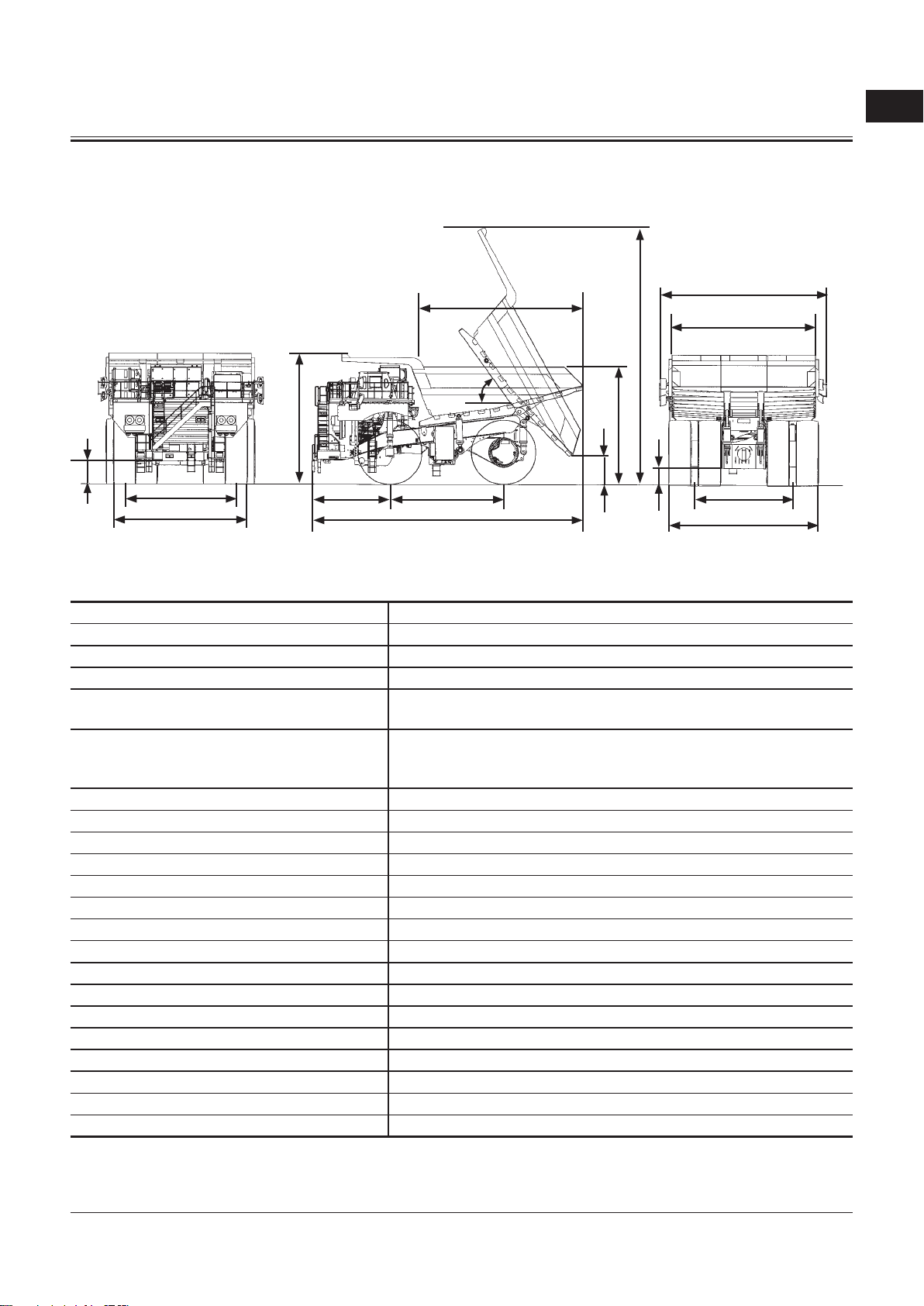
Machine Specifications..................................................... T1-1-1
Group 2 Component Layout
Main Component Layout................................................. T1-2-1
Operator's Seat .................................................................... T1-2-2
Liquid Crystal Display (LCD) (Normal Operation
Screen)............................................................................... T1-2-3
Console Panel....................................................................... T1-2-4
Engine, Driving, and Hydraulic Related Alarm
Indicators.......................................................................... T1-2-5
Headlight, Front Combination Light/Horn................ T1-2-6
Side Light............................................................................... T1-2-7
Rear Light............................................................................... T1-2-8
Maintenance Light ............................................................. T1-2-9
Electrical Component Box (Behind Cab) .................T1-2-10
Fuse Box ...............................................................................T1-2-11
Relay Box..............................................................................T1-2-12
Battery Relay Box .............................................................T1-2-13
Hydraulic Component.....................................................T1-2-14
Main Pump System...........................................................T1-2-14
Operator’s Seat Environment .......................................T1-2-15
Front Axle.............................................................................T1-2-16
Brake......................................................................................T1-2-17
Steering Cylinder ..............................................................T1-2-18
Hoist Cylinder.....................................................................T1-2-18
Suspension Cylinder ........................................................T1-2-19
Rear Axle Housing ............................................................T1-2-19
Control Cabinet (1) ...........................................................T1-2-20
Control Cabinet (2) ...........................................................T1-2-21
Terminal Board (TB3)-Output Connector.................T1-2-22
Breaker, Fuse, Relay, Others...........................................T1-2-23
Auxiliary Alternator Field Regulator (AFR) Unit......T1-2-24
Control Power (CS) Unit..................................................T1-2-25
Contactor, Relay, Others .................................................T1-2-26
Drive System Controller (DSC) .....................................T1-2-27
Rectifier (REC) Unit ...........................................................T1-2-28
Inverter (INV) Unit.............................................................T1-2-29
Fan Unit ................................................................................T1-2-30
Main Alternator Field Regulator (MFR) Unit............T1-2-31
Grid Box................................................................................T1-2-32
Group 3 Component Specifications
Engine..................................................................................... T1-3-1
Engine Accessories............................................................. T1-3-5
Alternator............................................................................... T1-3-6
Control Cabinet ................................................................... T1-3-7
Pump Device ........................................................................ T1-3-9
Travel Device.......................................................................T1-3-10
Brake Device .......................................................................T1-3-12
Steering Device .................................................................T1-3-13
Suspension Device ...........................................................T1-3-14
Hoist Device........................................................................T1-3-15
Fuses and Others...............................................................T1-3-16
Relay and Others...............................................................T1-3-19
Sensors .................................................................................T1-3-22
Lights.....................................................................................T1-3-24
Filter.......................................................................................T1-3-25
Others ...................................................................................T1-3-26
SECTION 1
GENERAL
CONTENTS
Find manuals at https://best-manuals.com

T1-1-1
Group 1Machine Specifications
SECTION 1GENERAL
Machine Specifications
ModelEH5000AC-3
Dump Body Capacity (Heap) 202 m3(264 yd3)
Operating Weight 204000 kg (450000 lb)
Nominal Payload With Standard Equipment 296000 kg (653000 lb)
Target Gross Machine Operating Weight
(TGMOW) 500000 kg (1100000 lb)
Engine
Cummins QSKTTA60-CE
2125 KW/1900 min-1
(2889 PS/1900 rpm)
A: Overall Length 15510mm (50 ft 11 in)
B: Overall Width 9600 mm (31 ft 6in)
C: Overall Height 7410mm (24 ft 4in)
D: Wheel Base 6500 mm (21 ft 4in)
E. E’: Tread (Front Tire/Rear Tire WT) 6370 mm (20 ft 11 in)/5610mm (18ft 5in)
F. F’: Tires Overall (Front Tire/Rear Tire) 7790 mm (25 ft 7in)/8660 mm (28 ft 5in)
G. G’: Ground Clearance (Front Axle/Rear Axle) 1010mm (3 ft 4in)/970 mm (3 ft 2in)
H: Front Overhang 4480 mm (14ft 8in)
I. J: Body Inside (Length/Width) 9790 mm (32 ft 1 in)/8150 mm (26 ft 9in)
K: Body Height 6710mm (22 ft 0in)
L. L’ Body Dump Height (Max./Min.) 14500 mm (47 ft 7in)/1840 mm (6 ft 0in)
M: Body Dump Angle51º
Minimum Turning Diameter (ISO) 29.9 m(98 ft 1 in)
Travel Speed Forward 56 Km/h (35 mile/h) Reverse 10Km/h (6.2 mile/h)
Electric Drive Hitachi AC-Drive System
Tires Size 53/80R63
fNOTE: These specifications are subject to change without notice.
G
E
F
C
HD
A
I
K
L’
L
J
B
G’ E’
F’
MQHA-12-001
M
Find manuals at https://best-manuals.com

SECTION 1GENERAL
T1-2-1
Group 2Component Layout
Cab1-
Brake Valve2-
Steering Valve3-
Relay Box (Bumper)4-
Battery (4 Used)5-
Grid Box (4 Used)6-
Control Cabinet7-
Front Brake Accumulator8-
Rear Brake Accumulator9-
Main Accumulator10-
Relay Box11-
Radiator12-
Engine13-
Front Axle(Right)14-
Tire (Front Right)15-
Front Wheel (Right)16-
Steering Cylinder (Right)17-
Main Alternator/Auxiliary18-
Alternator
Fuel Tank19-
Main Pump 120-
Main Pump 221-
Gear Pump (for Rear Brake22-
Cooling Oil)
Wheel Reduction Device23-
(Right)
Tire (Rear Right)24-
Wheel Motor (Right)25-
Parking Brake (Right, Left)26-
Rear Axle27-
Wheel Motor (Left)28-
Tire (Rear Left)29-
Wheel Reduction Device (Left)30-
Hydraulic Oil Tank31-
Steering Cylinder (Left)32-
Front Wheel (Left)33-
Tire (Front Left)34-
Front Axle(Left)35-
Frame36-
Suspension Cylinder (Front37-
Right, Front Left)
Hoist Cylinder (Right, Left)38-
Body39-
Suspension Cylinder (Rear40-
Right, Rear Left)
Alternator Blower41-
Wheel Motor Blower42-
Hoist Control Valve43-
Drive Shaft44-
Wheel Reduction Device45-
Cooling System
TQHA-01-02-033
T8DS-03-09-061
MQHA-07-008 MQHA-07-009
4039383714241712
14, 35 27 44 43
Main Component Layout
6
7
3
11
10
9
8
2
4
1
5
24232220, 211918171615141312
25,
26,
27,
28,
45
35 29303132333436

Group 2 Component Layout
SECTION 1 GENERAL
T1-2-2
2
5
431
15
14
13 12 11 1098
7
6
M8R7-03-003
Operator's Seat
Steering Wheel1-
Grid Dry Switch2-
Radio3-
Console Panel4-
Camera Monitor5-
Air Conditioner Unit6-
Shift Lever7-
Hoist Lever8-
Dump Override Switch9-
Load Dump Brake Switch10-
Accelerator Pedal11-
Electric Brake Pedal12-
Service Brake Pedal13-
Turn Signal/High Beam Lever14-
Horn Switch15-

Group 2Component Layout
SECTION 1GENERAL
T1-2-3
22
21 201918 17 15 141613 12
98765432
11
10
1
Engine Related Warning1-
Indicator
Speedometer (With2-
Odometer)
Left Turn Signal Indicator3-
STOP Indicator/CAUTION4-
Indicator
Driving Related Warning5-
Indicator
Right Turn Signal Indicator6-
Tachometer7-
Hydraulic Related Warning8-
Indicator
Hour Meter9-
Light Indicator10-
Fuel Gauge11-
Brake/Steering Hydraulic Oil12-
Pressure Gauge
Payload Indicator13-
Wheel Motor Temperature14-
Gauge
Shift Lever Indicator15-
Coolant Temperature Gauge16-
Engine Oil Pressure Gauge17-
Message Display Area18-
SAE Code Display Area19-
Clock20-
HCM Code Display Area21-
Dump Body AngleIndicator22-
Liquid Crystal Display (LCD) (Normal
Operation Screen)
TQHA-01-02-035

Group 2 Component Layout
SECTION 1 GENERAL
T1-2-4
13
21
17
14
23
165
11
15
194786
12
18
2022191023
M8R7-01-004
Console Panel
Cruise Control/Auto Retard1-
Main Switch
Cruise Control/Auto Retard2-
Speed Setting Switch
Not Used (Optional)3-
Parking Brake Switch4-
Air Conditioner Control Panel5-
Key Pad6-
Emergency Engine Stop7-
Switch
Key Switch8-
Headlight Switch9-
Not Used (Optional)10-
Not Used (Optional)11-
Side Deck Light Switch12-
Manual Rear Light Switch13-
Entrance Light Switch14-
Wiper/Washer Switch15-
AC Drive Fault Reset Switch16-
Cigar Lighter17-
Dimmer Switch18-
Buzzer Deactivation Switch19-
Engine Room Work Light20-
Indicator
Rear Axle Work Light Indicator21-
Camera Monitor22-
Liquid Crystal Display (LCD)23-

Group 2Component Layout
SECTION 1GENERAL
T1-2-5
Engine, Driving, and Hydraulic Related Indicators
22
21
13
20
17161514121110
5
6
498732
19
18
1
Engine Related Indicator
1-Engine Warning Indicator
2- Engine Oil Pressure Warning Indicator
3- Coolant Level Warning Indicator
4- Coolant Overheat Warning Indicator
5- Air Filter Restriction Warning Indicator
6- Alternator Indicator
Driving Related Indicator
7- Traction Warning Indicator
8- Wheel Motor Temperature Warning
Indicator
9- Wheel Motor/Alternator Cooling Blower
Warning Indicator
10- Electric Brake Indicator
11-Parking Brake Indicator
12- Load/Dump Brake Indicator
13- AC Drive Maintenance Request Indicator
Hydraulic Related Indicator
14- Hydraulic Oil Temperature Warning
Indicator
15- Steering Oil Pressure Warning Indicator
16- Hydraulic Oil Level Warning Indicator
17- Auto-Lubrication Error Warning Indicator
18- Hoist Lever Position Indicator
19- Dump Body Up Indicator
20- Stop Valve Warning Indicator
21-Grid Dry Indicator
22- Machine Control State Indicator
TQHA-01-02-035

Group 2 Component Layout
SECTION 1 GENERAL
T1-2-6
2
16
7
13
14
9
101112
543
8
TQHA-01-02-002
Headlight,Front Combination Light/Horn
Front Combination Light1-
(Right)
Headlight URO2-
Headlight URI3-
Headlight ULI4-
Headlight ULO5-
Front Combination Light (Left)6-
Horn (Left) High7-
Horn (Left) Low8-
Headlight LLO9-
Headlight LLI10-
Headlight LRI11-
Headlight LRO12-
Horn (Right) Low13-
Horn (Right) High14-

Group 2 Component Layout
SECTION 1 GENERAL
T1-2-7
Side Light
4
1
3
2
MQHA-01-002MQHA-01-005
Right SideLeft Side
Deck Mounted Manual Rear1-
Light (Left)
Deck Mounted Manual Rear2-
Light (Right)
Front Tire Light (Right)3-
Front Tire Light (Left)4-

Group 2 Component Layout
SECTION 1 GENERAL
T1-2-8
Rear Light
345
21
TQHA-01-02-034
Rear Combination Light (Left)1- Rear Combination Light2-
(Right)
Reverse Light (Right)3-
Backup Alarm Buzzer4-
Reverse Light (Left)5-

Group 2 Component Layout
SECTION 1 GENERAL
T1-2-9
5
3
24
1
A6
A - A AMQHA-01-012
MQHA-01-011
Light Mounting Position in Rear Axle
Maintenance Light
Entrance Light (1)1-
Entrance Light (2)2-
Entrance Light (3)3- Engine Room Work Light4-
(Right)
Engine Room Work Light (Left)5-
Rear Axle Work Light6-

Group 2 Component Layout
SECTION 1 GENERAL
T1-2-10
Electrical Component Box (Behind Cab)
15
13
12
5
7
14
11
9
10
4
1
6
83 2
Download Connector1-
Information Display Unit (IDU)2-
Central Control Unit (CCU)3-
Data Logging Unit (DLU)4-
Fuse (Refer to the next page.)5-
Flasher6-
DC/DC Converter7-
Optional Terminal Board8-
Engine Fault Indicator9-
AC Drive Shut Down Switch10-
Pump Manual Operation11-
Switch
Relay Box 1 (Refer to T1-2-12.)12-
Relay Box 2 (Refer to T1-2-12.)13-
Relay Box 3 (Refer to T1-2-12.)14-
Relay Box 4 (Refer to T1-2-12.)15-
M8R7-01-034
Other manuals for EH 5000AC-3
2
Table of contents
Other Hitachi Utility Vehicle manuals