Mami Home Guard User manual

HOME GUARD
MAMI
MANUFACTURING AND MINOR INVENTIONS
X00370 February 2012 home_guard.CDRV14


TABLE OF CONTENTS
HOME GUARD
HOME GUARD - FEATURES......................................................................................................................................
G E N E R A L D E S C R I P T I O N........................................................................................................................
WIRELESS DETECTORS AND REMOTE CONTROL OPERATION.....................................................................
PROGRAMING MODE................................................................................................................................................
SETTING TIMED SCHEDULES.....................................................................................................
SCHEDULE DAY BYPASS.............................................................................................................
AUXILIARY OPTIONS....................................................................................................................
ADJUST SIREN DURATION............................................................................
AUXILIARY BUZZER.......................................................................................
AUXILIARY SIREN...........................................................................................
ALARM OUTPUT INTERFACE.........................................................................
SETTING THE SYSTEM TIME.......................................................................................................
NAMING OF ZONES......................................................................................................................
SETTING TRANSMITTER CODE...................................................................................................
SETTING LEVELS...........................................................................................................................
CHANGING USER CODE..............................................................................................................
SELF LEARNING DETECTORS....................................................................................................
SELF LEARNING REMOTE’S........................................................................................................
CLEARING DETECTORS IN A ZONE............................................................................................
CLEARING REMOTE CONTROLS.................................................................................................
DEFAULTING THE ENTIRE SYSTEM............................................................................................
ARMING THE SYSTEM...............................................................................................................................................
ALARMS ON THE SYSTEM........................................................................................................................................
PANIC ACTIVATION....................................................................................................................................................
DIS-ARMING THE SYSTEM.......................................................................................................................................
ALERTS ON THE UNIT................................................................................................................................................
SYSTEM CONNECTIONS..........................................................................................................................................
USER NOTES.......................................................................................................:.....................................................
-1-
-2-
-3-
-4-
-4-
-4-
-5-
-5-
-5-
-5-
-5-
-6-
-6-
-6-
-7-
-7-
-7-
-8-
-8-
-9-
-9-
-9-
-10-
-10-
-11-
-12-
-5-
-6-
X00370 home_guard.CDR

GENERAL FEATURES:
HOME GUARD HOME GUARD
HOME GUARD
HOME GUARD
HOME GUARD :
- Supports a maximum of 25 wireless detectors.
- 8 individual wireless zones
- Supports up to 8 Remote Controls with different codes.
- LCD Display.
- Individual naming of zones(up to 16 characters)
- Arm/disarm via Keypad or Remote Control
- Buzzer output for auxiliary signals (arm, disarm, battery-low etc....).
- Flash memory for retention of both options and code selections during "power-down".
- Programmable Schedule for arming and disarming time windows ( hands free).
- Four preset active zone levels “A, B, C, or D”.
- Easy Arming.
- Easy programming and display of current options and settings .
- Self Learning function for the Remote Control code and Wireless Detectors.
- On Board wireless receiver.
- Monitoring and reporting of Tamper on Wireless Detector
- Monitoring and reporting of Battery low on wireless detectors
- Keypad wrong-code alert (allows 3 entries).
- Optional External Antenna.
- Receiver frequency at 433MHz
- Optional Transmitter at 403MHz
- Tracer Interface
HOME GUARD
The “ “ is a D.I.Y. stand-alone alarm panel, limited to receiving wireless signals. The “ ”
is capable of monitoring 25 wireless movement detectors divided into 8 different zones.
The “ ” support 8 different remote controls for arming, disarming and panic activation
The “ ” is fully programmable with an easy user interface. The external connections are limited to
power supply and optional siren outputs. Since the wireless receiver is onboard no other connections are
required, making installation an easy task. Adding wireless detectors and remote controls to the system is easy
with the self learning feature. The “ ” offers great flexibility and features
X00370 home_guard.CDR
Indoor Wireless Detector
Wireless Door Guard
Outdoor dual technology wireless Detector
Two Button Remote
-1-

-2-
GENERAL INFORMATION
- Supply Power: The “ “ operates from a
- Zones: The “ ” has allocation for 8 zones. All of these zones are wireless.
- Wireless Detectors: The “ ” can allow for a maximum of 25 wireless (Indoor and Outdoor)
detectors in all Zones. The “ ” supports both M.A.M.I. Passives as well as the Silentron detectors.
Adding wireless devices is an easy task. The user simply has to follow the instructions under the Add detectors
section of Programming mode.
- Remote’s: The “ ” supports a maximum of 8 Remote’s with MAMI smart code (16 bit).
- Antenna: The “ ” has an option for an external antenna. The external Antenna will allow
for a longer range. Typically the unit should be situated central to all detectors.
- Schedules: The “ ” has 2 programmable Schedules to automatically arm (Level A) and disarm the
unit at a specific time. Schedules can be disabled individually. The user can set the schedules to be bypassed for
one day. Note. It is Recommended that the Schedules be used with a backup power supply.
(see Programming mode Schedules and schedule bypass)
- Siren Output: The “ ” has a relay output, which activates on alarm. The duration that the Relay is
activated is determined by the siren duration option under the Programming mode.
- Tamper: If any of the detectors are tampered with, the detectors will send out a Tamper Signal which
sounds an alarm notifying the user, the zone in which the detector is will be displayed.
- Battery Low: If any of the detectors send a battery low signal the unit will illuminate the Trouble led and buzz
continuously. The battery low signal will only be received in the Disarmed state. The zone number or zone name
will be displayed.
- Four Programmable levels: The Programmable levels is a feature whereby the user can select which zones are
to be monitored when the system is armed. If a zone is not in the level the zone will not be monitored for alarms.
This unit has four levels which can be modified under the programming mode (set level’s A,B,C,D).
- Options: The user can select the Aux options of the unit. The options that the user can
select is the buzzer and Siren options. If the user sets the aux buzzer off, the buzzer will only sound on
an alarm. If the user selects the Aux Siren Off, the siren wont alert the user on arm and disarm but will sound on
Alarms.
HOME GUARD
HOME GUARD
HOME GUARD
HOME GUARD
HOME GUARD
HOME GUARD
HOME GUARD
HOME GUARD
12 Volts DC, 1A Power Supply.
- Zone Names: the zone names must be set by the user, this is to allow the user to easily identify which zone is in
alarm. If the zone name is not set the Zone number will be shown on alarm. setting the zone names can be seen
under the programming section - set Zone names.
- Transmitter output: If the unit has an internal transmitter, it could be used to interface any one of the following
devices: the Ghatto two channel receiver(16 bit), or Tracer smart cat receiver (Mami Smart-S interface 16 bit).
To adjust theses parameters refer to Programing Options, Options, Alarm Output interface.
X00370 home_guard.CDR

Using Wireless Sensors is simple provided you are aware of the following facts:
1 - The operating range may vary widely from one installation and location to another. The position of the radio receiver
which is in the unit is therefore critical and must be chosen accordingly.
2- Each installation requires to learn two different I.D. Codes :
- a DETECTOR CODE for sensors and detectors and...
- a REMOTE CONTROL CODE for the hand held remote controls
- Each code has two parts: IDENTIFICATION and FUNCTION
-IDENTIFICATION : This is the part that makes that device recognizable by the system.
-FUNCTION : This part is done on the unit. (see Programming mode adding detectors)
A 2 BUTTON REMOTE CONTROL IS USED: FOR PANIC ACTIVATION(BUTTON A) , FOR ARM/DISARM (BUTTON B)
WIRELESS DETECTORS AND REMOTE CONTROL OPERATION
To program the sensors and detectors see the instructions supplied with each device
IMPORTANT!!!:
- A wireless detector transmits an alarm condition only for a short period of time (2 - 4 Seconds)
- To save power the sensors are designed not to transmit if continuous movement is detected.
- A detector will only transmit if either a 30 seconds (test mode ) or 3 minutes (normal mode) has
elapsed from the last detection.
X00370 home_guard.CDR
-3-

FACTORY DEFAULT
"USER CODE"
= 1 0 0 0
0 #010
0 # 0 1010
Setting Schedules ARM & DISARM
PROGRAMMING THE HOME GUARD
- 4 -
SYSTEM PROGRAMMING OPTIONS
The programming mode is where the users set certain OPTIONS, adjusting the
operation of the unit to suit their needs. The unit will enter the programming mode
once the user ENTERS the user password followed by a hash “#” Key.
“Programming Mode” will be displayed on the LCD display. Once in programming
mode the user can adjust certain features of the unit as required by the user.
THE HOME GUARD IS ORIGINALLY PROGRAMMED WITH A "FACTORY
DEFAULT" SET OF OPTIONS. ALTHOUGH THE "FACTORY" OPTIONS
REFLECT THE CHOICE OF THE MAJORITY OF INSTALLERS AND END-
USERS, PROPER OPERATION AND COMPLIANCE WITH SPECIFIC
REQUIREMENTS CAN BE ACHIEVED THROUGH RE-PROGRAMMING.
“ ” will be displayed. Indicating that the
time for schedule 1 ARM must be entered. The user must enter the
time in a 24 hour format with hour first followed by the minute.
.
SCHEDULE 1 ARM time
If The user wishes to disable a schedule, instead of entering the
time; the ‘D’ KEY must be pressed
If the user enters an invalid time, “ERROR” will be displayed
and no changes will be made.
Once the user enters the time the user then enters the hash key
saving the time corresponding to the time the unit will automatically
arm.
“SCHEDULE 1 DISARM time” will be displayed. Indicating that the
time for schedule 1 DISARM must be entered.
Once the user enters the time the user then enters the hash key
saving the time corresponding to the time the unit will automatically
Disarm.
The user simply follows this same procedure for schedule 2
M MH H
D
Schedule Disable
Apply Changes
#
Save Changes
#
X00370 home_guard.CDR
MMH H
0 # B B010
Schedule Day Bypass
“Schedule Bypass” will be displayed. the user is prompted to
enter 1 for schedule bypass to be active or 0 to deactivate
schedule bypass.
Once the user enters the code the user then enters the hash key
saving the new user code.
1
BYPASS ON
0
BYPASS OFF
Save Changes
#
NOTE: The Schedule bypass option only bypasses the
Schedule for 1 day, to disable the schedule follow instructions
under setting schedules.

Programming Options
- 5 -
X00370 home_guard.CDR
0 # 0 2010
Auxiliary options
“Sound Options” will be displayed. If the user wishes, the user could adjust any one of the following by
entering the corresponding keys:
0 # 0 2010
Adjust Siren Duration
A
“Siren Duration” will be displayed. The user will have to select
between three options, either 30 second, 1 minute or 3 minute
interval.
Once the user is done the user will press the hash “#” key to
save the settings. The number pressed will be displayed.
3
2
1
Siren Duration 30 Seconds
Siren Duration 1 Minute
Siren Duration 3 Minutes
Save Changes
#
Auxiliary Buzzer
0 # 0 2010B
“Aux Buzzer” will be displayed. The user may then enter 1 or 0
to toggle the buzzer on or off respectively.
1
0
AUX BUZZER ON
AUX BUZZER OFF
Save Changes
#
Once the user is done the user will press the hash “#” key to
save the settings.
0 # 0 2010
Auxiliary Siren Signals
C
“Aux Siren” will be displayed. The user may then enter 1 or 0 to
toggle the Aux Siren ON or OFF respectively.
Note this will disable the siren Arm and Disarm signals.
1
0
AUX SIREN ON
AUX SIREN OFF
Save Changes
#
Once the user is done the user will press the hash “#” key to
save the settings.
0 # 0 3010
Setting System Time
“ ” will be displayed. Indicating that the current time must
be entered. The user must enter the time in a 24 hour format
with hour first followed by the minute.
Set Time
If the user enters an invalid time, “ERROR” will be displayed
and no changes will be made.
Once the user enters the time the user then enters the hash key
saving the time.
M MH H
Save Changes
#
0 # 0 2010
Alarm Output Interface
D
“Output Interface” will be displayed. If the board is fitted with a
transmitter select either Siren Transmitter output (When using a
Ghatto receiver connected to a siren) or tracer interface when
using the home guard as a tracer interface.
1
0
Siren Transmitter Enabled
Relay Enabled
Save Changes
#
Once the user is done the user will press the hash “#” key to
save the settings.
2
Tracer Interface Enabled
NOTE: THE UNIT COULD BE FITTED WITH EITHER A RELAY OR A
TRANSMITTER THE USER WILL HAVE TO SELECT THE CORRECT
OPTION ACCORDING TO THE UNIT TYPE

Programming Mode
0 # 0 4010
“Zone Naming” will be displayed. then the user is prompted to
enter a zone to name. The user must enter the zone number,
between 1 and 8 in this unit.
If the user enters an invalid Zone, it will be ignored.
Once the user enters the name the user then enters the hash key
saving that name. When the alarm goes off, instead of the zone
number the zone name will be displayed. Note The Zone number
will flash bellow as well.
Save Changes
Enter Zones (1-8)
The user must now enter the zone name with the keypad operating
as a telephone keypad. the user is allowed a maximum of 16
characters per zone. The Key ‘B’ represents a backspace or
delete.
B
Back space
The user is now prompted to enter a zone or Press hash to exit. if
the user wishes to name another zone the user keys in the zone
number or hash to exit. Continue with zone ‘Z’
keyed in
Naming of Zones
Z
#
2
ABC
Exit
#
Z
0 # 0 A010
Setting Level
The user must key in the user code followed by ‘0' then the level A,
B, C or D. the user must select active zones ( zones 1 to 8).
Once the user enters the active Zones associated with that level
the user then enters the hash key saving the Zones to that level. Save Changes
#
0B
/ /
0C0D
/
If the user enters an invalid Zone, it will be ignored.
The active zones on the level will be displayed, inactive zones will
be displayed as a blank.
1, ,3, , ,6, ,8
Edit Level - A
0 # 1 1010
Changing User Code
“Change User Code” will be displayed. the user is then prompted
to enter new Code. The user must enter the new Code.
If the user enters an invalid code or times out, “ERROR” will
be displayed and no changes will be made.
Once the user enters the hash key the user is then prompted to re-
enter the new user code.
0 01 0
Save Changes
#
#
Once the user enters the code the user then enters the hash key
saving the new user code.
0 01 0
NOTE: The default user code is 1000.
X00370 home_guard.CDR
- 6 -
0 # 0 5010
Transmitter Code
Enter the Transmitter code in decimal format. This code will be
transmitted on trigger. To send a test code press the 4 and 6 button
Once the user enters the code the user then enters the hash key
saving the code. Save Changes
#
3 41 2

-7-
Programming Mode
0 # 1 A010
Self-learning Detectors
“ADD Device” will be displayed. The user is asked to trigger the
device, the user must force the device to trigger.
If the panel received the code the user will be asked to enter the
Zone. The panel will allocate the device to this Zone
If the code has already been added, or exists in the system the
unit will ask the user if it must add the device. The user can
press star ”*” to continue or hash ”#” to exit.
Z
Enter Zones (1-8)
EXIT
#
Continue
*
The user is then prompted to add another device in which the user
has to follow the same procedure again. the user can press star
“*” to continue and hash “#” to save and Exit
0 # 1 B010
Self-learning Remote Controls
“ADD Remote” will be displayed. The user is prompted to trigger
the remote, the user must press any button on the remote.
If the panel received the code the user will be prompted that the
remote is added.
The user is then prompted to add another remote in which the user
has to follow the same procedure again. The user can press star
“*” to continue and hash ”#” to save and Exit
Remote Added
Trigger Remote
Trigger Device
X00370 home_guard.CDR
EXIT
#
*
Continue
EXIT
#
Continue
*
NOTE: THIS OPERATION WILL ERASE
ALL PRESENT DETECTORS ALLOCATED TO
THE ZONE CHOSEN. !
0 # 2 1010
Clearing Devices in a Zone
The user is prompted to enter the Zone to clear devices. Only the
Zone entered will be cleared. Note. only one zone at a time may be
erased
If the user wishes to exit, the user simply pushes the hash key instead.
The user is then prompted that the zone has been cleared and the
operation is complete.
Z
Enter Zones (1-8)
EXIT
#

-8-
Programming Options
0 # 2 2010
Clearing Remote Controls
The user is prompted to clear the remote’s. To continue the user
pushes any key.
If the user wishes to exit, the user simply pushes the hash “#” key
instead.
The user is then prompted that the Remote Controls has been
cleared.
Z
Enter Any Key Not Hash to
continue
EXIT
#
NOTE: THIS OPERATION WILL ERASE
ALL PRESENTLY STORED REMOTE
CONTROLS ALLOCATED TO THE UNIT.
!
0 # 2 9010
Defaulting The Entire System
The user is asked to Reset to factory settings. To continue the user
pushes any key other than the Hash “#” key.
If the user wishes to exit, the user simply pushes the hash key
instead.
The user is then prompted that the System has been Reset to
default settings.
Z
Enter Any Key Not Hash to
continue
EXIT
#
NOTE: THIS OPERATION WILL ERASE
ALL PRESENT SETTINGS TO DEFAULT. ALL
ALLOCATED DEVICES AND REMOTE’S WILL
BE CLEARED AS WELL. !
Notes:
X00370 home_guard.CDR
WARNING MODE ON THE HOME-GUARD
The Home Guard 64 can be put into a WARN or Chime mode. In
this mode the unit will not trigger an alarm but sound a chime when
any detector in the level has been triggered. To set warn Level (A-
D) The User simply Holds down desired Key (A-D) and the star
key for approx 2 seconds until the Beep.
The Level in warn mode and the Armed Zones will be shown.
Zones Not in the arm level will be displayed as an X
1•X 3 X X 6 X 8• • • • • •
Warning LEVEL - A
*A
+

-9-
ARMING THE HOME-GUARD
The Arm mode is when the unit becomes active in monitoring alarms. The unit can be armed in any of the
following ways:
- Remote Arm- In this mode the unit Arms to level A only.
- Schedule Arm when the unit reaches the scheduled time it will arm automatically. Arms to Level A only.
- Keypad Arm The user can choose to Arm at a particular level by holding down any of keys A - D.
To Arm Level A The User simply Holds down Key A until the Beep.
The siren should sound once if the Aux Siren option is selected.
A
The Level Armed and the Armed Mask will be shown.
1,X,3,X,X,6,X,8
ARMED LEVEL - A
ALARMS ON THE UNIT
Alarms on the unit will occur when any of the 8 zones are triggered, the panic on the remote was triggered or the panic
on the keypad was triggered.
When the unit goes into alarm, the unit will beep continuously and the siren relay will activate. The siren relay stays
activated for the duration chosen by the user; under programming options- siren duration. Default is 2 minutes. The
buzzer however continues to sound until the user disarms the system. The LCD will display the name of the alarm Zone
that went off and the zone in the level displayed will blink Example zone 3 is named lounge. Lounge will be displayed
and zone 3 of the level will blink.
If the Zone was not named the zone number will be displayed.
1,X,3,X,X,6,X,8
LOUNGE
Blinking
1,X,3,X,X,6,X,8
ALARM ZONE-3
Blinking
PANIC ACTIVATION
When the unit goes in panic the system goes into alarm and the siren,
together with the buzzer is activated. The display will show PANIC!!!.
PANIC!!!
To deactivate a panic the user must disarm the system.
ARM/DISARM
PANIC ACTIVATION
With the two channel Remote the panic is activated by pressing
button 1 as described in the figure.
On the Keypad the user can activate a panic by holding down the hash
“#” and star “*” key together.
*#
+
To Arm via the Remote the user presses the Arm/Disarm button,
button 2 on the Remote. ARM/DISARM
PANIC ACTIVATION
X00370 home_guard.CDR
2
1
1
2

DISARMING THE HOME-GUARD
If the unit is armed, the unit can be disarmed in any of the following ways:
- Remote Disarm.
- Schedule Disarm when the unit reaches the scheduled time it will disarm automatically.
- Keypad Disarm.
To disarm the unit via the keypad the user enters the user code
followed by hash and hash, as can be seen below.
Disarmed!!!
To Disarm via the Remote the user presses the Arm/Disarm button,
button 2 on the remote. ARM/DISARM
PANIC ACTIVATION
0 01 0 # #
If the unit is successfully Disarmed, the unit will display Disarmed
and Beep twice, and the siren should beep twice if the Aux siren
option is selected.
If the wrong code is entered, the user is allowed three tries to
disarm the unit. Each try will be displayed on the LCD display.
After the third wrong entry, the unit will go into alarm.
Try -3
Counts down to 0
ALERTS ON THE UNIT
In the case that any of the sensors added to the system has a
battery low condition the sensor will transmit that condition to
the unit. The unit will light up the Trouble LED. The user may
push the star key and hold it down until the battery low zone is
displayed (either the zone name or the zone number). the user
wont be notified which sensor it is but will only be notified which
zone the sensor is in.
Battery Low
Lounge
BATTERY LOW ON SENSORS ALERT.
Battery Low
Zone - 5
In the case that any of the senors added to the system has a
Tamper condition the sensor will transmit that condition to the
unit. The unit will light up the Trouble LED, Tamper and the
zone will be displayed
and the alarm will be sound. The user may push the
star key and hold it down the tamper alarm will be cleared. The
user wont be notified which sensor it is, but will only be notified
which zone the sensor is in.
(either the zone name or the zone
number)
TAMPER!!!
Lounge
TAMPER ON SENSORS ALERT.
TAMPER!!!
Zone - 5
Clear Alerts:
The user simply pushes the star key and hold it, then the alerts
will be cleared.
*
Notes:
-10-
X00370 home_guard.CDR
1
2
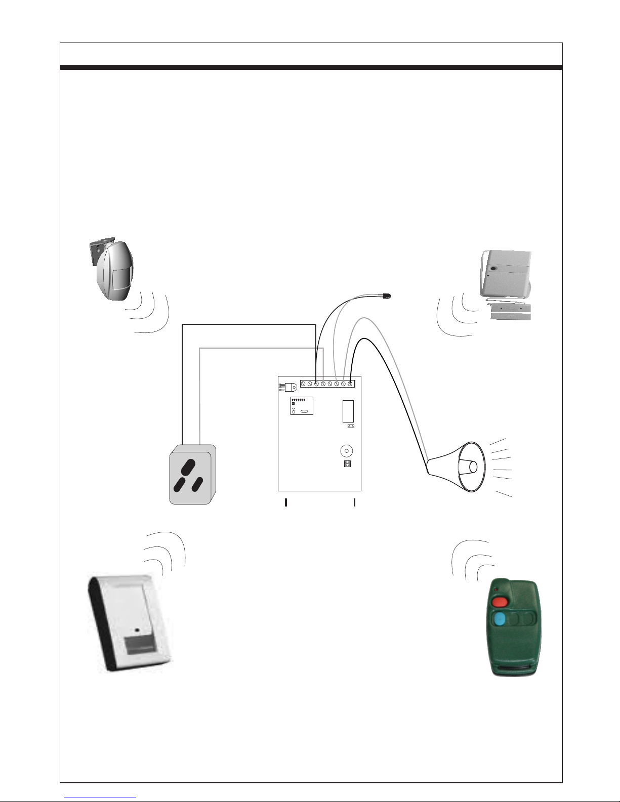
HOME-GUARD CONNECTIONS
-11-
Figure 1
Installing the "HOME-GUARD" is very simple. All you have to do is connect the power to the unit and the siren.
The connections are easy to read and to understand all detectors are wireless and easy to add to the unit with
no additional effort.
- ALARM CIRCUIT CONNECTIONS:
There are 8 different zones available on the HOME GUARD which are all wireless.
- SIREN: 12 Volts DC- 1Amp is available between connectors [LED]( - ) & [LED]( + ) to operate the siren
NOTE: ONLY THE RELAY OPTION OR THE TRANSMITTER OPTION CAN BE SELECTED.
- DC - SUPPLY: A 12 Volts DC, 1A Power Supply.
X00370 home_guard.CDR
Each wireless detector must be identified within the system.
This is done under the programming options and
not on the Detectors in this model.
12V DC
KEYPAD
+ - A B - +
LED
SIREN
C & D Not Connected
A Not Connected
+
-
+-
EXTERNAL
LED
+
-
NOTE: SIREN RELAY OPTION IS ONLY AVAILABLE
IF THE HOME GUARD HAS THE RELAY FITTED AND
NOT THE TRANSMITTER FITTED.

Notes:
-12-
X00370 home_guard.CDR

Summary of ALL Key-Pad entries
PROGRAMMING THE OPTION REGISTERS (ONLY THROUGH TO THE USER CODE)
1000 # 0 1 = SET SCHEDULES OF THE SYSTEM
1000 # 0 2 = SET OPTIONS OF THE SYSTEM
1000 # 0 3 = SET THE SYSTEM TIME
1000 # 0 4 = SET NAMES FOR EACH ZONE.
1000 # 0 5 = SET TRANSMITTER CODE.
1000 # 0 A = SET LEVEL A
1000 # 0 B = SET LEVEL B
1000 # 0 C = SET LEVEL C
1000 # 0 D = SET LEVEL D
1000 # 1 1 = CHANGE USER CODE
1000 # 1 A = SELF LEARN DETECTORS
1000 # 1 B = SELF LEARN REMOTE’S
1000 # 2 1 = ERASE DEVICES IN ZONE
1000 # 2 2 = ERASE ALL REMOTE’S FROM THE SYSTEM
1000 # 2 9 = RESET ENTIRE UNIT TO DEFAULT
PANIC
[ *& #] --> [*&#] = SEND PANIC SIGNAL
NOTES:
A-->A Means: Press and hold the A key until it beeps
[*&A -->*&A] Means: Press and hold the * and the A keys until it beeps
[ Y ] Means: Any COMBINATIONS OF numbers 1,2,3,4,5,6,7 or 8
[ * ] Denotes the value when password has been activated (No default exist!)
[7&9] Means: Press BOTH KEYS (7&9) at the same time
[ Z ] Means: keys A, B, C, D OR any combination of 1,2,3,4,5,6,7 or 8
Arming the Unit
A --> A = SET ARM LEVEL A
B --> B = SET ARM LEVEL B
C --> C = SET ARM LEVEL C
D --> D = SET ARM LEVEL D
Appendix “A”
VIEW OTHER ALERTS
* --> * = CLEAR TROUBLE ALERTS
X00370 home_guard.CDR
MAMI
MANUFACTURING AND MINOR INVENTIONS
Warn the Unit
*&A -->*&A = SET WARN LEVEL A
*&B -->*&B = SET WARN LEVEL B
*&C -->*&C = SET WARN LEVEL C
*&D -->*&D = SET WARN LEVEL D
TEST SIGNAL
[ 4& 6] --> [4&6] = SEND TEST SIGNAL THROUGH TRANSMITTER.

Appendix “A”
X00370 home_guard.CDR
Radio Receiver range
In all radio applications the positioning of the antennae on both transmitter and receiver is very important.
Incorrect positioning and mounting of the units may reduce the range drastically.
Obstacle such as walls , steel gates, caboards , floors, metal structure and of course distance are the
main factors which may reduce the range.
The receiver unit is manufactured with an internal antenna which caters for most of the applications.
better results are obtained by taking such antenna out of the box as shown in the pictures below
For applications where longer range is required or where the console is mounted in a
confined space surrounded by many any of the above obstacle you can request a special unit which
is supplied with an external antenna already connected to the unit
Table of contents
Other Mami Security System manuals


Popular Security System manuals by other brands

Federal Signal Corporation
Federal Signal Corporation 2001-130 Installation and operating instructions

Defender
Defender PHOENIX quick start guide

Swann
Swann Fourtify quick start guide

Radionics
Radionics Security System user guide

PATROLLINE
PATROLLINE HPS 940 instructions

Visonic
Visonic POWERMAX - user guide


