AJAX vhfBridge User manual

vhfBridge User Manual
Updated December 10, 2021
vhfBridge is a module for connecting Ajax security systems to third-party VHF
transmitters. It provides 8 transistor outputs for connection to third-party VHF
transmitters.
The device is powered from 100–240V ~ mains and can be operated from a
12V⎓ backup battery.
The vhfBridge operates as part of the Ajax security system by connecting via
the secure radio communication protocol to the hub. The hub
communication range is up to 1800 meters without obstacles. Comes in two
congurations: with and without a casing.
Functional elements
Body elements
Jeweller
Buy vhfBridge

The presence of the casing depends on the vhfBridge package. Devices come in two
congurations: with and without a casing.
vhfBridge board elements
1. Screws securing the body lid. Unscrew with bundled hexagon key (Ø 4 mm).
2. Cavity for a 12V backup battery.
Battery not included with vhfBridge set.
3. QR code and ID (serial number) of the device.
4. Perforated part of the body. It is necessary for tamper triggering in case of
dismounting attempts.
5. Perforated part of the body for the output of wires of connected detectors
and devices.

vhfBridge terminals
1. Terminals for connecting a 12 V⎓ backup battery.
2. Power supply input 100–240 V~.
3. Tamper button. Signals if vhfBridge body lid is removed.
4. Power button.
5. LED indicator.
6. QR code and ID (serial number) of the device.
7. Terminals for connecting a third-party VHF transmitter.
BATT — input for 12 V⎓ backup power connection

LED indication
vhfBridge LED indicator may light up white, red, or green, depending on the
status of the device.
Please note that the LED indicator is not visible when the body lid is closed. The
LED indicator is used at the stage of connecting and conguring the vhfBridge.
In the future, the state of the device can be monitored in the Ajax app.
LED indication Event Note
Lights white.
Connection with the hub is
established, external power
supply is connected.
Lights red.
There is no connection with
the hub, external power supply
is connected.
For example, the hub is turned
off or vhfBridge is outside the
coverage area of the hub’s
wireless network.
Goes out for 0.5 seconds, then
lights up green and turns off. Enabling vhfBridge.
Goes out for 0.5 seconds, then
lights up green and fades out
over 3 seconds.
Disabling vhfBridge.
Blinks red once per second. vhfBridge is not assigned to a
OUT — power output for the 12 V⎓ VHF transmitter (maximum output
current 2 A)
OUT1…8 — vhfBridge outputs for connecting a third-party VHF transmitter

hub.
Lights up for a second once
every 10 seconds.
No external power supply is
connected to vhfBridge.
The colour of the indication
depends on the status of
connection with the hub:
During an alarm, gradually
lights up and goes out once
every 10 seconds.
No external power supply and
discharged external battery of
vhfBridge.
The colour of the indication
depends on the status of
connection with the hub:
LED indication of output status
LED indication Output status in case of alarm
High potential output (positive trip). Lights up green.
Low potential output (negative trip). Goes out.
Operating principle
vhfBridge is designed to connect third-party VHF transmitters to create an
additional channel for transmitting events to the CMS.
The communication channel with the CMS created using vhfBridge can be used
as the only or as a backup channel for communicating with the CMS (more
reliable option). This means that the hub can simultaneously transmit all events
and alarms to the monitoring station of the security company not only through
SIA, Contact ID, and other proprietary protocols but also using vhfBridge.
The transponder receives information about alarms and events from the hub via
the Jeweller radio channel. vhfBridge then transmits it to a third-party VHF
lights up white if there is
connection with the hub;
lights up red if there is no
hub connection.
lights up white if there is
connection with the hub;
lights up red if there is no
hub connection.

transmitter over the wires. The VHF transmitter, in turn, transmits all events and
alarms to the CMS via a radio channel.
Events can be transmitted to the CMS via the internet and vhfBridge in parallel.
Transmission via the internet works as the main channel because of greater
reliability and informativity. The transmitted events may contain the zone
number of the triggered detector, group number, user number, and other data.
vhfBridge works as a backup communication channel and duplicates all events
transmitted via the internet. The delivery speed of events and alarms in both
cases does not exceed 1 second.
An example of the algorithm of actions in case of an alarm from a
MotionProtect motion detector:
1. MotionProtect has detected an alarm.
2. MotionProtect transmits the alarm to the hub via the Jeweller radio
protocol.
3. The hub receives the MotionProtect alarm and transmits it to vhfBridge via
the Jeweller radio protocol.
4. vhfBridge receives the alarm from the hub and transmits it to the third-party
VHF transmitter over a wired connection.
5. The VHF transmitter receives the alarm and transmits it to the radio receiver
on the CMS side via the radio channel.
6. The radio receiver receives the alarm and transmits it to the CMS software.
7. The CMS receives and processes the alarm.

Output types
vhfBridge has 8 potential outputs for connection to a VHF radio transmitter.
There are two types of outputs:
The positive trip (high-potential output) does not supply voltage in the normal state. As
soon as an alarm or event occurs, the output supplies a voltage of 12–14 V⎓. The
negative trip (low-potential output) works the other way around. In the normal state, the
voltage is maintained at 12–14 V⎓, and when an alarm or event occurs, the voltage
drops to 0 V.
The vhfBridge output type and alarm pulse duration are congurable in Ajax
apps.
VHF transmitter power supply
vhfBridge can supply a third-party VHF transmitter with 12 V⎓ power (maximum
output current 2 A).
If the VHF transmitter has a current consumption of more than 2 A, it can be
powered by the vhfBridge battery. In this case, disable battery charge tracking in
the vhfBridge settings so that the system users do not receive notications
about the vhfBridge battery charging too long.
vhfBridge event transmission to the monitoring station
Ajax security system can also connect to the CMS and transmit alarms to the
monitoring station in Sur-Gard (Contact ID), SIA (DC-09), and other proprietary
protocol formats. See a complete list of supported protocols .
The vhfBridge loop (zone) number can be found in the device states:
1. High potential output (positive trip).
2. Low potential output (negative trip).
here
Which CMSs can the Ajax security system be connected to

The vhfBridge loop (zone) number is also available in the Groups menu (Ajax
app → Devices → Hub → Settings → Groups). To learn the loop (zone)
number, select the group in which the transponder or the required connected
device is located. The Device number corresponds to the loop (zone) number.
Adding to the system
vhfBridge does not work , , , and third-party security central
units. Only user with administrator rights in Ajax PRO application can add and congure
devices.
Before adding a device
1. Sign in to the .Ajax app
2. Go to the Devices menu.
3. Select vhfBridge. The loop (zone) number is displayed at the very bottom of
the page.
Hub ocBridge Plus uartBridge
1. Install the . Create an . Add a hub to the app and
create at least one virtual room.
Ajax PRO app account

Only one vhfBridge can be connected to one compatible Ajax hub.
In order to connect vhfBridge
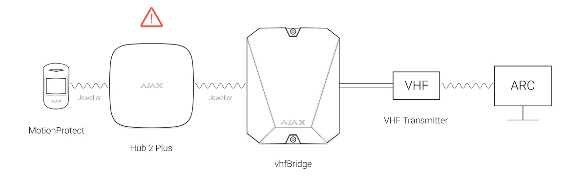
For the detection and pairing to occur, the transponder should be located within the
coverage area of the hub’s wireless network (at the same guarded object).
If the connection has failed, disconnect vhfBridge for 5 seconds and try again. If
the transponder has already been assigned to another hub, turn off vhfBridge
and then follow the standard addition procedure.
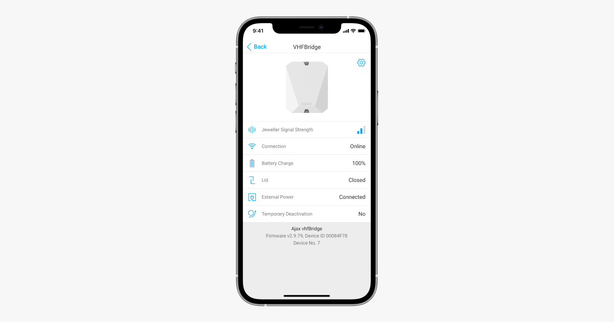
The connected transponder will appear in the list of hub devices in the app.
Updating device statuses depends on Jeweller settings. The default status
update period in the app is 36 seconds.
2. Check that the hub is on and has access to the internet (via Ethernet cable,
Wi-Fi, and/or mobile network). You can do this in the Ajax app or by
checking the hub logo on the faceplate. The logo should light up white or
green if the hub is connected to the network.
3. Ensure that the hub is disarmed and does not start updates by checking its
status in the Ajax app.
1. Open the . If your account has access to multiple hubs, select the
one to which you want to add vhfBridge.
Ajax app
2. Go to the Devices tab and click Add device.
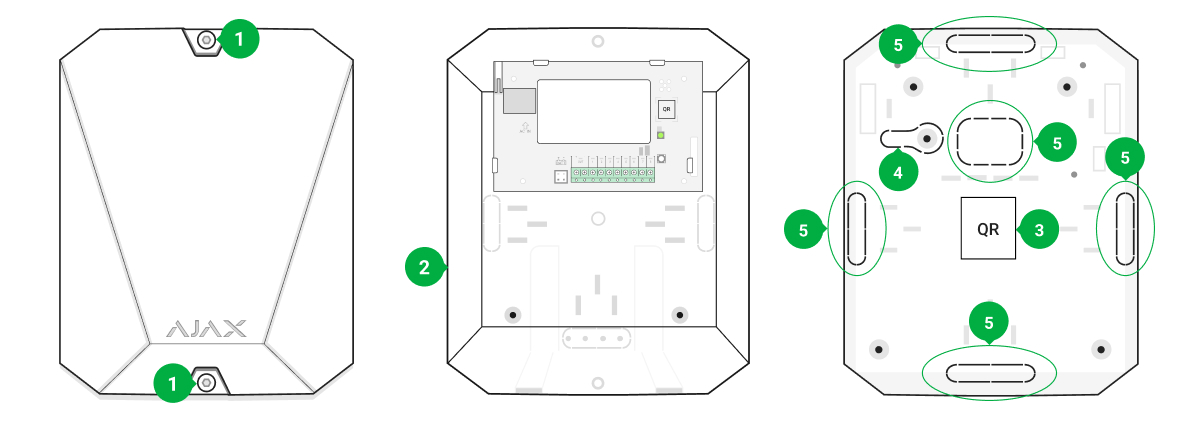
3. Name the transponder, scan or enter the QR code manually (located on the
device body and packaging), and select a room and a group (if the group
mode is activated).
4. Click Add; the countdown will begin.
5. Switch on vhfBridge by holding the power button for 3 seconds. Keep in
mind that the hub connection request is only transmitted when the
integration module is switching on.

Faults counter
When a vhfBridge malfunction is detected (e.g., no external power), the Ajax app
will display a red icon with a number in the upper left corner of the device icon.
The number indicates the number of faults.
All faults can be seen in the transponder states. Fields with faults will be
highlighted in red.
Icons

Icons display some vhfBridge states. You can view them in the Ajax app, in the
Devices tab.
Icon Meaning
Jeweller Signal Strength. Displays the signal strength between the hub and
vhfBridge.
The recommended value is 2-3 bars.
The charge level of the battery connected to vhfBridge.
Displays when vhfBridge is operating via a .
vhfBridge is temporarily disabled.
vhfBridge tamper triggering events are temporarily disabled.
States
States can be found in the :
Parameter Meaning
Malfunction
Click to open the list of vhfBridge
malfunctions.
The eld is displayed only if a battery charge
fault is detected.
Jeweller Signal Strength
Signal strength between the hub and vhfBridge.
The recommended value is 2-3 bars.
radio signal range extender
Learn more
Learn more
Ajax app
1. Go to the Devices tab.
2. Select vhfBridge from the list.

Connection Connection status between the hub and
vhfBridge:
Battery charge
Battery charge level of the device. Displayed as
a percentage.
Also, this eld can display the battery status:
Lid
The status of tampers that respond to
detachment or violation of the integrity of the
body.
External power
The presence of external power supply 100–
240 V:
ReX “range extender name”
Radio signal range extender connection status:
Please note that the eld is displayed if
vhfBridge is operated via a
.
Temporary Deactivation Shows the status of the device temporary
deactivation function:
Online — the device is connected
Oine — no connection to the device
How battery charge is displayed in
Ajax apps
Charging — displayed while the battery is
being charged
Error — displayed if the battery has been
charging for more than 40 hours
What is a tamper
Connected — external power supply is
connected
Disconnected — external power supply is
disconnected
Online — the device is connected
Oine — no connection to the device
radio signal
range extender

Firmware vhfBridge rmware version.
ID vhfBridge ID (serial number). Also located on
the device box, its board, and the body.
Device № Number of the device loop (zone).
vhfBridge settings
Settings can be changed in the :
No — the device operates normally and
transmits all events
Lid only — the hub administrator has
disabled notications about triggering on
the device body
Entirely — the device is completely excluded
from the system operation by the hub
administrator. The device does not follow
system commands and does not report
alarms or other events
Ajax app
1. Go to the Devices tab.
2. Select vhfBridge from the list.
3. Go to Settings by clicking on the icon in the upper right corner.
4. Set the required parameters.

Note that after editing the settings, you should click the Back button to save them.
Setting Meaning
First eld
vhfBridge name. It is displayed in the text of
SMS and notications in the event feed.
To change the device name, click on the pencil
icon .
The name can contain up to 12 Cyrillic
characters or up to 24 Latin characters.
Room
Selecting the virtual room to which vhfBridge is
assigned.
The room name is displayed in the text of SMS
and notications in the event feed.
Monitoring of the battery charging duration
Set up of the battery charging duration.
When this option is enabled, the system will
send a malfunction notication if the battery
connected to vhfBridge has been charging more
than 40 hours.
Disable monitoring if the third-party VHF radio
transmitter is powered directly from the battery
and not from the vhfBridge power terminals.
Pulse duration
Pulse time on an event (from 1 to 255 seconds).
Set in increment of 1 second.
The default value is 5 seconds.
Jeweller Signal Strength Test Switches vhfBridge to the Jeweller signal
strength test mode.
The test allows you to check the signal strength
between the hub and vhfBridge and determine
the optimal installation location.
5. Click Back to save the new settings.

Temporary Deactivation
Allows the user to disable the device without
removing it from the system.
Two options are available:
User Guide Opens vhfBridge User Guide in the Ajax app.
Unpair Device Unpairs vhfBridge, disconnects it from the hub,
and deletes its settings.
Conguring vhfBridge outputs
By default, vhfBridge outputs are congured as follows:
The settings of outputs can be changed in the :
What is Jeweller Signal Strength
Test
Deactivate entirely — the device will not
execute system commands or participate in
automation scenarios, and the system will
ignore device alarms and other notications
Deactivate lid notications — the system
will ignore only notications about the
triggering of the device tamper button
Learn more about temporary
deactivation of devices
1st output — intrusion
2nd output — panic button
3rd output — malfunction
4th output — tamper
5th output — loss of vhfBridge power supply
6th output — power loss of the hub
7th output — hub battery discharged
8th output — loss of communication between the hub and vhfBridge
Ajax app

Setting Meaning
Event type
Selection of the event type to which vhfBridge
output reacts.
A complete list of event types and their icons is
Connection type of the output
Selection of the output type:
Event types of vhfBridge outputs
Event type Description Icon
Not assigned Output disabled
Intrusion alarm The alarm of opening,
movement, and breaking of
detectors
1. Go to the Devices tab.
2. Find vhfBridge in the list of devices.
3. Go to the Outputs menu.
4. Find the output in the list and go to its Settings by clicking on the gear icon
.
5. Set the required parameters.
6. Click Back to save the new settings.
available below
High potential output (positive trip).
Low potential output (negative trip).

Fire Fire alarm
Medical alarm Medical alarm Button
Panic button
Any alarm Alarm of any connected
detector
Malfunction Any malfunction of the
connected detectors
Power loss of the transponder Loss of main power of
vhfBridge
Panic button clicking in
Ajax apps
Clicking DoubleButton
Clicking Button in panic
button mode
Clicking a panic button
connected to Transmitter
or MultiTransmitter

Transponder battery
discharged vhfBridge battery discharged
Power loss of the hub Loss of hub main power
Hub battery discharged The hub battery is discharged
Lid Tamper triggering of any
device
Change of security modes
Changing the security mode of
an object or a group (bistable
output)
Conrmed intrusion alarm Conrmed alarm (according to
PD 6662: 2017)

Conrmed hold-up device
alarm
Conrmed hold-up device
alarm (according to PD
6662:2017)
Lost connection with vhfBridge
Loss of vhfBridge connection
with the hub via Jeweller
channel
The following vhfBridge outputs work in the bistable mode:
All other outputs work in the pulse mode.
Connecting VHF transmitter to vhfBridge
List of recommended VHF transmitters
Learn more
Learn more
Arming status
Hub power
vhfBridge power
Hub battery status
vhfBridge battery status
Hawk VHF Alarm Transmitter from FSK Electronics
TX750C from RDC

vhfBridge can be connected to any VHF transmitter with relay inputs. Connection via
UART, RS-485, and other interfaces is not supported.
How to connect a VHF transmitter to vhfBridge
When connecting the VHF transmitter, do not twist the wires together, but solder them.
The ends of the VHF transmitter wires, which will be inserted into the vhfBridge
terminals should be tinned or crimped with a special sleeve.
TR-41 from Puper
1. Turn off the vhfBridge power (if power was connected).
2. Turn off vhfBridge.
3. Select vhfBridge outputs to which you want to connect the VHF transmitter.
4. Pull the VHF transmitter wires into the vhfBridge body through the holes.
There are perforated sections on the body that can be broken off and the cable can
be pulled through them.
5. Connect the VHF transmitter to the control outputs of vhfBridge according
to the wiring diagram in the User Guide supplied by the VHF radio
transmitter manufacturer.
6. Fasten the cable securely to the vhfBridge terminals using a straight
screwdriver (slot PL 3.0).
7. Connect the power to the third-party VHF transmitter.
If a VHF transmitter requires 12 V power to operate, it can be connected to the
power terminals of the corresponding vhfBridge zone. Do not connect the external
power supply to the transmitter power terminals, as this may damage the device.
Other manuals for vhfBridge
2
Table of contents
Other AJAX Security System manuals

AJAX
AJAX DoubleButton User manual

AJAX
AJAX HomeSiren User manual

AJAX
AJAX StreetSiren User manual

AJAX
AJAX HomeSiren User manual

AJAX
AJAX StreetSiren User manual

AJAX
AJAX StreetSiren User manual

AJAX
AJAX KeyPad User manual

AJAX
AJAX StreetSiren User manual

AJAX
AJAX Hub 2 Plus User manual

AJAX
AJAX KeyPad User manual
Popular Security System manuals by other brands

Global Fire Equipment
Global Fire Equipment Valkyrie AS Series quick start guide

Bosch
Bosch GVS1000 Operation manual

Swann
Swann NightHawk Twin Pack SW233-WX2 Specification sheet

Vimar
Vimar by-me Eikon Series Instruction booklet

x-sense
x-sense Link SC06-W user manual

Sylvania
Sylvania SY14Q2144 Series instruction manual