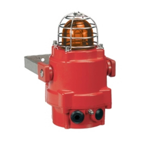
Pfannenberg Quadro LED-RGB-3G/3D User manual

Betriebsanleitung Quadro LED-RGB-3G/3D
07/2020 Seite 1 / 7 086200012
de
en
fr
it
ru
Schutzvermerk nach DIN ISO 16016 beachten!
Originalsprache
Inhalt
1. Bestimmungsgemäße Verwendung..............................................................................................................1
2. Lieferumfang....................................................................................................................................................1
3. Abmessungen..................................................................................................................................................2
4. Technische Daten ...........................................................................................................................................2
4.1 Allgemein...............................................................................................................................................2
4.2 Elektrische Kenndaten ..........................................................................................................................3
5. Normenkonformität/ Kennzeichnungen........................................................................................................3
6. Inbetriebnahme................................................................................................................................................4
6.1 Sicherheitshinweise...............................................................................................................................4
6.2 Montage und Installation.......................................................................................................................5
6.3 Elektrischer Anschluss..........................................................................................................................6
6.4 Einstellung der Betriebsarten................................................................................................................6
6.5 Externe Ansteuerung der Betriebsarten................................................................................................6
7. Option...............................................................................................................................................................7
8. Wartung, Service, Instandhaltung.................................................................................................................7
9. Außerbetriebnahme, Demontage und Entsorgung......................................................................................7
1. Bestimmungsgemäße Verwendung
Multifunktionsleuchten der Type Quadro LED-RGB-3G/3D sind für die optische Signalisierung von z.B. Gefahr-
zuständen oder für die Zustandsanzeige von Maschinen und Anlagen bestimmt. Die Lichtsignale werden durch
LEDs mit hoher Lebenserwartung und robusten mechanischem Aufbau erzeugt.
Die Leuchten sind für den Einsatz in explosionsgefährdeter Umgebung der Zone 2 gemäß EN 60079-10-1 und
Zone 22 gemäß EN 60079-10-2 geeignet. Die Leuchten können für Gase der Temperaturklassen T1, T2, T3,
T4, T5 und T6 eingesetzt werden. Die Leuchten können ebenfalls in Umgebungen mit nichtleitenden Stäuben
eingesetzt werden. Eine Oberflächentemperatur des Gehäuses von 80°C wird nicht überschritten.
Die LED im Leuchtenteil kann in verschiedenen Betriebsarten betrieben werden, die mithilfe eines internen
Schalters eingestellt werden können. Den einzelnen Betriebsarten können unterschiedliche Farben zugeordnet
werden.
Zusätzlich besteht die Möglichkeit, über externe Ansteuerung alternative Betriebsarten und Farben zu wählen.
Die Geräte nur in unbeschädigtem Zustand innerhalb der spezifizierten Kenndaten betreiben.
Die Geräte sind für den Einsatz im Innen- und Außenbereich geeignet und nur für die ortsfeste Montage be-
stimmt.
2. Lieferumfang
Der Lieferumfang besteht aus:
1x Signalgerät
1x Kurz-Betriebsanleitung
1x CE-Erklärung
1x Satz Befestigungslaschen

Betriebsanleitung Quadro LED-RGB-3G/3D
07/2020 Seite 2 / 7 086200012
de
3. Abmessungen
Bohrbild; Ansicht von unten
Befestigungslasche
Montageschraube
z.B. M4x20
Verschluss-
schraube M20x1,5
Kabelverschraubung
M20x1,5
4. Technische Daten
4.1 Allgemein
Quadro LED-RGB-3G/3D
Lichtstärke max.
8 cd (Signalfarbe Gelb, Blitzlicht 1 Hz, Hauptabstrahlrichtung)
Leuchtmittel
1x Hochleistungs-LED (RGBW)
Farben
blau, rot, grün, gelb
zusätzlich über externe Ansteuerung: weiß
Einschaltdauer
100%
Anschlussklemmen
Federzugbügel
0,13 - 2,5mm² feindrähtig / AWG26 - AWG 14
0,25 –1,5mm² AEH / AWG23 –AWG 16
Schutzart
IP 66/67 (EN 60529)
Schlagfestigkeit
IK08 (EN 50102)
Schutzklasse
II
Betriebstemperatur
-20 °C…+55 °C
Lagertemperatur
-20 °C…+70 °C
Max. rel. Luftfeuchte
90%
Kabeleinführung
2 x M20x1,5
Dichtbereich der Kabelver-
schraubung
7 –12 mm
Gehäusematerial
Polycarbonat (PC) lichtgrau, RAL 7035
Haubenmaterial
Polycarbonat (PC)
Einbaulage
beliebig
Haubenfarbe
weiß

Betriebsanleitung Quadro LED-RGB-3G/3D
07/2020 Seite 3 / 7 086200012
de
4.2 Elektrische Kenndaten
Bemessungsspannungsbereich
12 V –48 V DC
115 V –230 V AC
Arbeitsspannungsbereich
10 –57 V DC
95 –253 V AC
Bemessungsfrequenz
--
50/ 60 Hz
Bemessungsstromaufnahmebereich
276 mA –64 mA
51 mA –36 mA
Bemessungsleistung (max.)
3,3 W
8,3 VA
Arbeitsspannung
12 V
24 V
48 V
115 V
230 V
Stromaufnahme RMS
(Leuchtfarbe Gelb)
[mA]
Blitzlicht 0,75 Hz
159
73
41
33
25
Blitzlicht 1 Hz
183
85
47
37
27
Dauerlicht
76
41
33
31
25
Blinklicht 1 Hz
54
30
25
24
21
Blitzlicht 2 Hz
276
120
64
51
36
Blinklicht 2 Hz
51
27
22
25
22
Blitzlicht 0,1 Hz
60
28
19
20
19
Blitzlicht 0,5 Hz
131
60
34
28
22
DFM3 (Option)
214
96
53
43
32
Stromaufnahme max.
(Leuchtfarbe Gelb)
[mA]
Blitzlicht 1 Hz
583
291
167
396
372
Blitzlicht 2 Hz
578
290
168
392
368
Blinklicht 2 Hz
86
55
52
158
170
5. Normenkonformität/ Kennzeichnungen
Normenkonformität: Richtlinie 2014/34/EU (ATEX)
(Explosionsschutz) EN 60079-0: 2012 + A11:2013
EN 60079-15: 2010
EN 60079-31: 2014
Kennzeichnung: II3G Ex nRc IIC T6 Gc (-20°C Ta +55°C)
PDG 20.0008 X II3D Ex tc IIIB T80°C Dc IP66/67 (-20°C Ta +55°C)
Besondere Verwendungsbedingungen X:
Nach den Anforderungen der EN 60079-0 ist das Gerät für einen niederen Grad der mechanischen Gefahr ge-
eignet. Das heißt:
➢Das Gerät vor Schlag geschützt montieren.
Ein Schutzkorb ist nicht zwingend erforderlich.
Zur Verhinderung möglicher gefährlicher elektrostatischer Entladungen der Gehäuseoberfläche in gasexplosi-
onsgefährdeten Bereichen die Sicherheitshinweise in der Betriebsanleitung beachten:
➢Das Gerät nur feucht reinigen.
➢Um unabsichtliches trockenes Abreiben zu verhindern wird eine Einbauhöhe von > 2,50m vorgeschla-
gen oder aber vergleichbare Schutzmaßnahmen.
Das Gerät ist für den Anschluss an fest verlegte Anschlussleitungen vorgesehen. Die Kabelverschraubungen
sind für ortsfest verlegte Kabel und Leitungen geeignet.
Ein Öffnen des Gerätes nach der Installation ist im Regelfall nicht vorgesehen. Sollte ein Öffnen des Gerätes
trotzdem notwendig werden (z.B. für eine Änderung der Betriebsart oder Austausch von Originalersatzteilen):
➢Sicherheitshinweise beachten!
➢Kapitel 8. Wartung, Service, Instandhaltung beachten!

Betriebsanleitung Quadro LED-RGB-3G/3D
07/2020 Seite 4 / 7 086200012
de
6. Inbetriebnahme
6.1 Sicherheitshinweise
GEFAHR - Kennzeichnet eine außergewöhnlich große Gefahrensituation. Wird dieser Hinweis nicht beachtet,
kommt es zu schweren irreversiblen Verletzungen oder zum Tod.
WARNUNG - Kennzeichnet eine außergewöhnlich große Gefahrensituation. Wird dieser Hinweis nicht beach-
tet, sind schwere irreversible oder tödlichen Verletzungen möglich.
VORSICHT - Kennzeichnet eine Gefahrensituation. Wird dieser Hinweis nicht beachtet, kann es zu leichten
oder mittleren Verletzungen kommen.
GEFAHR–Explosionsfähige Atmosphäre!
➢Das Gerät nicht öffnen, wenn explosionsfähige Atmosphäre vorhanden sein kann!
➢Nach dem Abschalten der Betriebsspannung Entladungsphase von 10 Minuten für die
elektrischen Komponenten abwarten. Erst danach Gerät öffnen.
GEFAHR–Verwendungsbedingungen (X) beachten:
(siehe Kapitel 5. Normenkonformität/ Kennzeichnungen)
Schlagfestigkeit!
➢Das Gerät vor Schlag geschützt montieren.
Elektrostatische Entladung!
➢Das Gerät nur feucht reinigen. Unabsichtliches und trockenes Abreiben verhin-
dern. Aus diesem Grund wird eine Einbauhöhe von > 2,50m vorgeschlagen oder
aber vergleichbare Schutzmaßnahmen.
Schwadensicherheit:
➢Die Dichtung des Gerätes vor dem Zusammenbau auf Sauberkeit und Beschädi-
gung kontrollieren. Geräte mit beschädigter Dichtung nicht verwenden.
Kabeleinführung:
➢(nur zugelassene Kabelverschraubungen verwenden, siehe Mindestanforderungen
der Kabelverschraubungen)
Nur für fest verlegte Anschlussleitungen geeignet.
GEFAHR–Explosionsfähige Atmosphäre!
➢Das Gerät niemals außerhalb der spezifizierten Umgebungstemperaturen betreiben:
Tamb: -20°C Ta +55°C
➢Das Gerät niemals außerhalb der spezifizierten Kenndaten betreiben.
GEFAHR- Lebensgefahr durch Stromschlag
Spannungsführende Geräte und freiliegende Anschlussleitungen können Stromschläge erzeugen
und schwere Unfälle verursachen.
➢Arbeiten an elektrischen Anschlüssen dürfen nur elektrotechnisch geschulte und autori-
sierte Fachkräfte durchführen.
➢Vor der Montage alle Zuleitungen spannungsfrei schalten und gegen Wiedereinschalten
sichern. Spannungsfreiheit immer sicherstellen.
➢Das Anlegen der Betriebsspannung darf nur bei fest verschlossenem Gehäuse erfolgen.
WARNUNG - Gefahr durch unzulässigen Einsatz der Geräte
Der nicht bestimmungsgemäße Einsatz kann zu schweren Unfällen führen.
➢Bei der Installation darauf achten, dass die Anschlussleitung gegen Zug und Verdrehen ab-
gesichert ist.
Die Geräte sind nur für die ortsfeste Montage bestimmt.
GEFAHR - Gefahr durch Beschädigung der Geräte
Nichtbeachtung der Typenschild-Angaben kann zu schweren Unfällen führen.
➢Bei Installation und Wartung der Geräte immer die Angaben auf dem Typenschild beachten.
➢Die chemische Beständigkeit des Kunststoffes Polycarbonat beachten.
VORSICHT - Verletzungsgefahr durch scharfe Kanten oder erhitzte Bauteile
➢Bei Installations-, Montage-, oder Service/ Wartungsarbeiten Handschuhe tragen.
➢Verdrahtung entfernt von scharfen Kanten, Ecken und internen Komponenten vornehmen.
VORSICHT - Beeinträchtigung des Sehvermögens
➢Um eine Beeinträchtigung des Sehvermögens zu verhindern, den dauernden, direkten
Blick in die aktivierte Leuchte vermeiden.

Betriebsanleitung Quadro LED-RGB-3G/3D
07/2020 Seite 5 / 7 086200012
de
6.2 Montage und Installation
➢Sicherheitshinweise beachten!
➢Bei allen Arbeiten national zutreffende Errichterbestimmungen beachten.
➢Besondere Verwendungsbedingungen beachten.
Installationsanforderungen:
➢Die Geräte in Übereinstimmung mit den aktuellen Ausgaben der entsprechenden Teile der EN 60079
oder gemäß gleichwertiger IEC-Spezifikation installieren.
EN 60079-10-1 Explosionsfähige Atmosphäre - Teil 10-1:
Einteilung der Bereiche - Gasexplosionsgefährdete Bereiche
EN 60079-10-2 Explosionsfähige Atmosphäre - Teil 10-2:
Einteilung der Bereiche - Staubexplosionsgefährdete Bereiche
EN 60079-14 Explosionsfähige Atmosphäre - Teil 14:
Projektierung, Auswahl und Errichtung elektrischer Anlagen
Mindestanforderungen der Kabelverschraubungen:
Ex-e Kabelverschraubung für einen zulässigen Temperaturbereich von -20°C … +85°C, ausgerüstet mit einem
O-Ring und der Schutzart IP 66/67. Ein langes Anschlussgewinde ist erforderlich >12mm.
Für die Sicherstellung der Schwadensicherheit des Gehäuses im Dauereinsatz sind Kabelverschraubungen
folgender Typen geprüft:
Hummel HSK-K-Ex-Active, M20x1,5, EG-Baumusterprüfbescheinigung BVS 14 ATEX E 025 X:
–Dichtbereich 7 –12 mm, Hummel Art.-Nr.: 1.292.2016.31 (im Werk montiert und geprüft)
–Dichtbereich 10 –14 mm, Hummel Art.-Nr.: 1.292.2016.30
Die Verschlussschraube kann durch oben genannte Kabelverschraubungen ersetzt werden.
Hinweis für die Auswahl der Anschlussleitung:
Die Temperatur von 70°C wird an der Kabeleinführungsstelle nicht überschritten.
➢Anschlussleitungen gegen Zug und Verdrehen absichern.
Installation:
➢Die vier Kreuzschlitzschrauben in der Haube lösen und diese nach oben hin abnehmen.
Bohrungen für die Montage des Gehäuses sind danach zugänglich, Maße siehe Kapitel 3. Abmessungen.
Alternative Montage mit den beigelegten Laschen möglich.
➢Elektrischen Anschluss auf der Platine in der Haube wie folgt vornehmen.
➢Nach der Einstellung der gewünschten Betriebsart das Gerät wieder verschließen.
➢Vor dem Zusammenbau auf eine saubere und unbeschädigte Dichtung achten. (Sicherstellung der
Schwadensicherheit). Geräte mit beschädigter Dichtung nicht verwenden.
➢Die vier Kreuzschlitzschrauben der Haube über Kreuz in mindestens zwei Durchgängen mit einem ab-
schließenden Drehmoment von ca. 1,5 Nm anziehen.
➢Zur Sicherstellung der zuverlässigen Signalisierung einen abschließenden Funktionstest durchführen.

Betriebsanleitung Quadro LED-RGB-3G/3D
07/2020 Seite 6 / 7 086200012
de
6.3 Elektrischer Anschluss
S1
Wahl der
Betriebsart
Steuerung der Lichtintensität
Blitzlicht 10 –100%
Blink- / Dauerlicht: 45 –100%
X1
Externer Steuereingang
X2 Betriebsspannungs-
anschluss:
DC:
AC:
Anschluss
der Leitung
Hinweis: Geräte mit DC-Spannung sind mit einem Verpolungsschutz ausgerüstet. Bei Verpolung der An-
schlüsse keine Funktion.
6.4 Einstellung der Betriebsarten
S1
Betriebsart
1
2
3
OFF
OFF
OFF
Blitzlicht 1 Hz *
OFF
OFF
ON
Blitzlicht 0,75 Hz
OFF
ON
OFF
Dauerlicht
OFF
ON
ON
Blinklicht 1 Hz
ON
OFF
OFF
Blitzlicht 2 Hz
ON
OFF
ON
Blinklicht 2 Hz
ON
ON
OFF
Blitzlicht 0,1 Hz
ON
ON
ON
Blitzlicht 0,5 Hz
OFF
OFF
ON
Doppelblitzmodus (DFM3) siehe Option
S1
Farbzuordnung
4
5
6
OFF
OFF
OFF
Rot *
OFF
ON
Blau
ON
OFF
Grün
ON
ON
Gelb
*Werkseinstellung
6.5 Externe Ansteuerung der Betriebsarten
S1
Betriebsart
1
2
3
4
C1/ C2
nicht
angesteuert
OFF
OFF
OFF
ON
Standby
Blinklicht 1 Hz
Dauerlicht
Dauerlicht
OFF
OFF
ON
Standby
Dauerlicht
Dauerlicht
Dauerlicht
OFF
ON
OFF
Standby
Blinklicht 1 Hz
Dauerlicht
Blinklicht 1 Hz
OFF
ON
ON
Standby
Blitzlicht 1 Hz
Dauerlicht
Dauerlicht
ON
OFF
OFF
Standby
Blitzlicht 1 Hz
Dauerlicht
Blinklicht 1 Hz
ON
OFF
ON
Standby
Blitzlicht 1 Hz
Dauerlicht
Blitzlicht 1 Hz
ON
ON
OFF
Standby
Blinklicht 1 Hz
Blinklicht 1 Hz
Blinklicht 1 Hz
ON
ON
ON
Standby
Blitzlicht 1 Hz
Blitzlicht 1 Hz
Blitzlicht 1 Hz
Option DFM
Standby
DFM1
DFM2
DFM3
OFF
OFF
ON

Betriebsanleitung Quadro LED-RGB-3G/3D
07/2020 Seite 7 / 7 086200012
de
S1
Farbzuordnung
C1/ C2
nicht
angesteuert
4
5
6
ON
OFF
OFF
Standby
Rot
Grün
Blau
OFF
ON
Standby
Rot
Grün
Gelb
ON
OFF
Standby
Rot
Grün
Weiß
ON
ON
Standby
Rot
Grün
Rot
7. Option
Doppelblitzmodus DFM
Über externe Ansteuerung besteht die Möglichkeit, zwischen DFM1, DFM2 und DFM3 zu wählen.
DFM1
DFM2
DFM3
8. Wartung, Service, Instandhaltung
➢Bei allen Arbeiten am Gerät Sicherheitshinweise beachten.
Das Gerät erfordert keine besondere Wartung.
Ein Öffnen des Gehäuses und Austausch der Dichtung ist nicht vorgesehen.
➢Das Gehäuse aus Polycarbonat nur mit Wasser und einem Hand-Spülmittel reinigen.
➢Für die Reinigung keine Lösungsmittel verwenden.
Der Austausch von Originalersatzteilen oder Einstellung einer anderen Betriebsart kann durch Elektrofach-
kräfte durchgeführt werden.
➢Nach dem Austausch eine Stückprüfung durchführen.
Die Prüfung auf Schwadensicherheit entsprechend EN 60079-15 Absatz 23.2.3.2.1.2 ist Bestandteil
dieser Prüfung (Änderung eines Unterdrucks von 3 kPa auf 2,7 kPa nicht schneller als in 27 s).
Kabelverschraubungen können als Prüfanschluss für den Test verwendet werden. Diese sind nach der
Prüfung mit einem ATEX-Verschlussstopfen zu verschließen.
➢Reparaturen grundsätzlich nur im Herstellerwerk ausführen lassen.
Umbauten, Änderungen, fehlerhafter und unzulässiger Einsatz sowie die Nichtbeachtung der Hinweise dieser
Betriebsanleitung schließen eine Gewährleistung aus.
9. Außerbetriebnahme, Demontage und Entsorgung
➢Bei allen Arbeiten am Gerät Sicherheitshinweise beachten.
➢Altgeräte nur von sachkundigen Personen und gemäß geltenden Umweltvorschriften entsorgen.
Altgeräte werden ebenfalls von Pfannenberg fachgerecht entsorgt. Die Anlieferung an eines unserer Her-
stellwerke hat kostenfrei zu erfolgen.
Pfannenberg GmbH
Werner-Witt-Straße 1
D- 21035 Hamburg
Tel.: +49/ (0)40/ 734 12-0
Fax: +49/ (0)40/ 734 12-101
service@pfannenberg.com
http://www.pfannenberg.com

Quadro LED-HI-3G/3D Operating Instructions
07/2020 Page 1 / 8 086200012
en
Content
1. Intended use...................................................................................................................................................1
2. Scope of delivery ...........................................................................................................................................1
3. Dimensions.....................................................................................................................................................2
4. Technical data ................................................................................................................................................2
4.1 General .......................................................................................................................................................2
4.2 Electrical data..............................................................................................................................................3
5. Conformity to standards/ designations.......................................................................................................3
6. Commissioning ..............................................................................................................................................4
6.1 Safety information.......................................................................................................................................4
6.2 Assembly and installation ...........................................................................................................................5
6.3 Electrical connection...................................................................................................................................6
6.4 Setting the operating modes.......................................................................................................................6
6.5 External control of the operating modes.....................................................................................................7
7. Option.............................................................................................................................................................8
8. Maintenance, service, repairs.......................................................................................................................8
9. Decommissioning, dismantling and disposal.............................................................................................8
1. Intended use
Quadro LED-RGB-3G/3D multi-functional lights are designed for the optical signaling of e.g. hazardous situa-
tions or for status displays of machines and systems. The light signals are generated by LEDs that have a long
life expectancy and a robust mechanical design.
The lights are suitable for use in potentially hazardous area of Zone 2, in accordance with EN 60079-10-1 and
in Zone 22, in accordance with EN 60079-10-2. The LEDs can be used for gases of temperature classes T1,
T2, T3, T4, T5 and T6.
The lights can also be used in environments with non-conductive dusts. The surface temperature of the hous-
ing will not exceed 80°C.
The LED in the light section can be operated in different modes, all of which can be activated by an internal
switch. Different colors can be assigned to the individual operating modes.
The option of selecting alternative operating modes and colors via external control is featured additionally.
The devices must only be operated when undamaged and within the specified parameters.
The devices are designed for indoor and outdoor use and are only intended for fixed installation.
2. Scope of delivery
The scope of delivery consists of:
1x Signaling device
1x Quick guide
1x CE declaration
1x Set of fixing brackets

Quadro LED-RGB-3G/3D Operating Instructions
07/2020 Page 2 / 8 086200012
en
3. Dimensions
Drilling pattern; view from
below
Fixing bracket
Mounting screw
e.g. M4x20
Sealing screw
M20x1.5
Cable gland
M20x1.5
4. Technical data
4.1 General
Quadro LED-RGB-3G/3D
Light intensity max.
8 cd (signal color yellow, flashing light 1 Hz, main radiation direction)
Light source
1x high-performance LED (RGBW)
Colors
blue, red, green, yellow
additionally via external control: white
Duty cycle
100%
Connecting terminals
Clamp cage
0.13 - 2.5mm² fine stranded / AWG26 - AWG 14
0.25 - 1.5 mm² AEH / AWG23 - AWG 16
Ingress Protection
IP 66/67 (EN 60529)
Impact strength
IK08 (EN 50102)
Protection class
II
Operating temperature
-20 °C…+55 °C
Storage temperature
-20 °C…+70 °C
Max. rel. air humidity
90%
Cable inlet
2 x M20x1.5
Sealing range of the cable
gland
7 –12 mm
Housing material
Polycarbonate (PC) light gray, RAL 7035
Lens material
Polycarbonate (PC)
Installation position
any
Lens color
white

Quadro LED-RGB-3G/3D Operating Instructions
07/2020 Page 3 / 8 086200012
en
4.2 Electrical data
Rated voltage range
12 V –48 V DC
115 V –230 V AC
Operation voltage range
10 –57 V DC
95 –253 V AC
Rated frequency
--
50/ 60 Hz
Rated current consumption range
276 mA –64 mA
51 mA –36 mA
Rated power (max.)
3.3 W
8.3 VA
Operation voltage
12 V
24 V
48 V
115 V
230 V
Current consumption
RMS
(LED color yellow)
[mA]
Flashing light 0.75 Hz
159
73
41
33
25
Flashing light 1 Hz
183
85
47
37
27
Continuous light
76
41
33
31
25
Blinking light 1 Hz
54
30
25
24
21
Flashing light 2 Hz
276
120
64
51
36
Blinking light 2 Hz
51
27
22
25
22
Flashing light 0.1 Hz
60
28
19
20
19
Flashing light 0.5 Hz
131
60
34
28
22
DFM3 (option)
214
96
53
43
32
Max. current con-
sumption
(LED color yellow)
[mA]
Flashing light 1 Hz
583
291
167
396
372
Flashing light 2 Hz
578
290
168
392
368
Blinking light 2 Hz
86
55
52
158
170
5. Conformity to standards/ designations
Conformity to standards: Directive 2014/34/EU (ATEX)
(Explosion protection) EN 60079-0
EN 60079-15
EN 60079-31
Designation II3G Ex nRc IIC T6 Gc (-20°C Ta +55°C)
PDG 20.0008 X II3D Ex tc IIIB T80°C Dc IP66/67 (-20°C Ta +55°C)
Special application conditions X
X: The device is suitable for a low degree of mechanical hazard in accordance with the requirements of EN
60079-0. This means:
➢The device must be mounted protected against impact.
A protective basket is not absolutely necessary.
Refer to the Safety information in the operating manual to prevent possible hazardous electrostatic discharges
from the housing surface in potentially explosive gas atmospheres:
➢The device must only be wet-cleaned.
➢Avoid unintentional and dry rubbing.
An installation height of > 2.50 m or comparable protective measures is therefore suggested.
The device is designed for connection to permanently installed connection cables. The cable glands are suita-
ble for stationary cables and wires.
The device is usually not intended for opening after installation.
If it should nevertheless become necessary to open the device (e.g. to change the operating mode or replace
original spare parts):
➢Observe the Safety information!
➢Observe chapter 8. Maintenance, service, repairs!

Quadro LED-RGB-3G/3D Operating Instructions
07/2020 Page 4 / 8 086200012
en
6. Commissioning
6.1 Safety information
DANGER- Indicates an unusually high-level hazardous situation. Non-compliance with this warning may result
in serious irreversible injury or death.
WARNING- Indicates an unusually high-level hazardous situation. Non-compliance with this warning may
result in serious, irreversible or fatal injury.
CAUTION - Indicates a hazardous situation. Non-compliance with this warning may result in minor or moder-
ate injury.
DANGER–Explosive atmosphere!
➢Do not open the device if a potentially explosive atmosphere may be present!
➢Wait 10 minutes for the electrical components to discharge after switching off the operating
voltage. The device should only be opened afterwards.
DANGER–Observe the application conditions (X):
(see 5. Conformity to standards/ designations)
Impact strength!
➢The device must be mounted protected against impact.
Electrostatic discharge!
➢The device must only be wet-cleaned. Avoid unintentional and dry rubbing. An in-
stallation height of > 2.50 m or comparable protective measures is therefore sug-
gested.
Vapor tightness control:
➢Check the seal of the device for cleanliness and damage prior to assembly. Do not
use devices with damaged seals.
Cable inlet:
➢(Only use approved cable glands, see Minimum requirements for cable glands)
Only suitable for permanently installed connection cables.
HAZARD–Explosive atmosphere!
➢Never operate the device outside the specified ambient temperatures:
Tamb: -20°C Ta +55°C
➢Never operate the device outside the specified data.
DANGER- Danger to life due to electric shock
Voltage-carrying devices and exposed connection cables may cause electric shocks and serious
accidents.
➢Only trained and authorized electricians may work on electrical connections.
➢Disconnect all supply lines from mains before installation and secure them against recon-
nection. Always ensure absence of voltage.
➢The operating voltage must only be applied when the housing is firmly closed.
WARNING - Danger due to unauthorized use of the devices
Improper use may lead to serious accidents.
➢Ensure that the connection cable is protected against pulling and twisting during installa-
tion.
The devices are only intended for fixed installation.
DANGER- Hazard due to damage to the devices
Non-compliance with the information on the type plate can lead to serious accidents.
➢Always observe the information on the type plate when installing and servicing the devices.
➢Observe the chemical resistance of the polycarbonate plastic.
CAUTION - Risk of injury due to sharp edges or heated components
➢Wear gloves during any installation, assembly or service/maintenance work.
➢Perform wiring tasks at a distance from sharp edges, corners and internal components.
CAUTION - Impairment of vision
➢Avoid constant, direct glances into the activated lights to prevent impairment of vision.

Quadro LED-RGB-3G/3D Operating Instructions
07/2020 Page 5 / 8 086200012
en
6.2 Assembly and installation
➢Observe the Safety information!
➢Observe nationally applicable installation regulations for all work.
➢Observe the Special application conditions X.
Installation requirements:
➢Install the devices in compliance with the current editions of the relevant parts of EN 60079 or equiva-
lent IEC specifications.
EN 60079-10-1 Potentially explosive atmospheres - Part 10-1:
Classification of areas subject to gas explosion
EN 60079-10-2 Potentially explosive atmospheres - Part 10-2:
Classification of areas subject to flammable dust
EN 60079-14 Potentially explosive atmospheres - Part 14:
Project planning, selection and installation of electrical systems
Minimum requirements for cable glands:
Ex-e cable gland for a permissible temperature range from -20°C ... +85°C, equipped with an O-ring and pro-
tection type IP 66/67. A long connection thread is necessary >12mm.
Cable glands of the following types have been tested to ensure that the housing is vapor-proof under continu-
ous use:
Hummel HSK-K-Ex-Active, M20x1,5, EC type-examination certificate BVS 14 ATEX E 025 X:
–Sealing range 7 –12 mm, Hummel type No.: 1.292.2016.31 (factory assembled and tested)
–Sealing range 10 –14 mm, Hummel type No.: 1.292.2016.30
The sealing screw can be replaced by the cable glands specified above.
Note for the selection of the connection cable:
The temperature of 70°C is not exceeded at the cable inlet point.
➢Protect connection cables against pulling and twisting.

Quadro LED-RGB-3G/3D Operating Instructions
07/2020 Page 6 / 8 086200012
en
Installation:
➢Loosen the four cross-head screws in the lens and remove them upwards.
The holes for mounting the housing are then accessible, for dimensions see chapter 3. Dimensions.
Alternative installation possible with the brackets supplied.
➢Perform electrical connection on the circuit board in the lens as follows.
➢Close the device again after setting the desired operating mode.
➢Ensure that the sealing is clean and undamaged before assembly. (Ensure vapor tightness). Do not
use devices with damaged seals.
➢Tighten the four cross-head screws of the lens crosswise in at least two rounds with a final torque of
approx. 1.5 Nm.
➢Carry out a final functional test to ensure reliable signaling.
6.3 Electrical connection
S1
Selection of
operating
mode
Light intensity control
Flashing light 10 –100%
Blinking / continuous light: 45 –100%
X1
External control input
X2 Operating voltage
connection
DC:
AC:
Connection of
the line
Note: Devices with DC voltage are equipped with reverse polarity protection. The function is guaranteed if the
polarity of the connections is reversed.
6.4 Setting the operating modes
S1
Operating mode
1
2
3
OFF
OFF
OFF
Flashing light 1 Hz *
OFF
OFF
ON
Flashing light 0.75 Hz
OFF
ON
OFF
Continuous light
OFF
ON
ON
Blinking light 1 Hz
ON
OFF
OFF
Flashing light 2 Hz
ON
OFF
ON
Blinking light 2 Hz
ON
ON
OFF
Flashing light 0.1 Hz
ON
ON
ON
Flashing light 0.5 Hz
OFF
OFF
ON
Double flash mode (DFM3) see Option
S1
Color assignment
4
5
6
OFF
OFF
OFF
Red *
OFF
ON
Blue
ON
OFF
Green
ON
ON
Yellow
*Factory setting

Quadro LED-RGB-3G/3D Operating Instructions
07/2020 Page 7 / 8 086200012
en
6.5 External control of the operating modes
S1
Operating mode
1
2
3
4
C1/ C2
not
activated
OFF
OFF
OFF
ON
Standby
Blinking light 1 Hz
Continuous light
Continuous light
OFF
OFF
ON
Standby
Continuous light
Continuous light
Continuous light
OFF
ON
OFF
Standby
Blinking light 1 Hz
Continuous light
Blinking light 1 Hz
OFF
ON
ON
Standby
Flashing light 1 Hz
Continuous light
Continuous light
ON
OFF
OFF
Standby
Flashing light 1 Hz
Continuous light
Blinking light 1 Hz
ON
OFF
ON
Standby
Flashing light 1 Hz
Continuous light
Flashing light 1 Hz
ON
ON
OFF
Standby
Blinking light 1 Hz
Blinking light 1 Hz
Blinking light 1 Hz
ON
ON
ON
Standby
Flashing light 1 Hz
Flashing light 1 Hz
Flashing light 1 Hz
Option DFM
Standby
DFM1
DFM2
DFM3
OFF
OFF
ON
S1
Color assignment
C1/ C2
not
activated
4
5
6
ON
OFF
OFF
Standby
Red
Green
Blue
OFF
ON
Standby
Red
Green
Yellow
ON
OFF
Standby
Red
Green
White
ON
ON
Standby
Red
Green
Red

Quadro LED-RGB-3G/3D Operating Instructions
07/2020 Page 8 / 8 086200012
en
7. Option
Double Flash mode
It is possible to choose between DFM1, DFM2 and DFM3 (Double Flash Mode) via the external control.
DFM1
DFM2
DFM3
8. Maintenance, service, repairs
➢Observe the Safety information during all work on the device.
The device requires no special maintenance.
The housing is not intended to be opened or the seal replaced.
➢Only clean the polycarbonate housing with water and a hand-washing cleaner.
➢Do not use solvents for cleaning.
Qualified electricians can replace original spare parts or set a different operating mode.
➢Perform a routine test after replacement.
The test for vapor tightness in accordance with EN 60079-15, par. 23.2.3.2.1.2 is part of this test
(change of a negative pressure from 3 kPa to 2.7 kPa not faster than in 27 s).
Cable glands can be used as a test connection for the test. These must be closed with an ATEX plug
after the test.
➢Repairs must always be carried out at the manufacturer's premises.
Conversions, modifications, improper and impermissible use as well as failure to observe the notes in this op-
erating instructions shall void any warranty.
9. Decommissioning, dismantling and disposal
➢Observe the Safety information during all work on the device.
➢Only properly qualified personnel should dispose of old devices in accordance with applicable envi-
ronmental regulations.
Old devices are also professionally disposed of by Pfannenberg. Delivery to one of our manufacturing fa-
cilities shall be free of charge.
Pfannenberg GmbH
Werner-Witt-Straße 1
D- 21035 Hamburg
Tel.: +49/ (0)40/ 734 12-0
Fax: +49/ (0)40/ 734 12-101
service@pfannenberg.com
http://www.pfannenberg.com

Instructions de service Quadro LED-RGB-3G/3D
07/2020 Page 1 / 7 086200012
fr
Respecter les symboles et clauses de protection de la
norme DIN ISO 16016 !
Traduction française
Sommaire
1. Utilisation conforme................................................................................................................................1
2. Contenu de la livraison...........................................................................................................................1
3. Dimensions..............................................................................................................................................2
4. Caractéristiques techniques..................................................................................................................2
4.1 Généralités............................................................................................................................................2
4.2 Caractéristiques électriques..................................................................................................................3
5. Conformité aux normes / marquages....................................................................................................3
6. Mise en service........................................................................................................................................4
6.1 Consignes de sécurité...........................................................................................................................4
6.2 Montage et installation ..........................................................................................................................5
6.3 Branchement électrique ........................................................................................................................5
6.4 Réglage des modes opératoires ...........................................................................................................6
6.5 Commande externe des modes opératoires.........................................................................................6
7. Option............................................................................................................................................................7
8. Maintenance, entretien, réparation ...............................................................................................................7
9. Mise hors service, démontage et élimination ..............................................................................................7
1. Utilisation conforme
Les feux multifonctions du type Quadro LED-RGB-3G/3D sont conçus pour la signalisation visuelle d’états
dangereux, par exemple, ou pour l’affichage de l’état des machines et des installations. Les signaux lumineux
sont générés par des DEL présentant une durée de vie élevée et une construction mécanique robuste.
Les feux sont adaptés à une utilisation dans des environnements explosifs de la zone 2 selon EN 60079-10-1
et de la zone 22 selon EN 60079-10-2. Les feux peuvent être utilisés pour les gaz des classes de température
T1, T2, T3, T4, T5 et T6.
Les feux peuvent également être utilisés dans des environnements avec des poussières non conductrices.
Une température de surface du boîtier de 80 °C n’est pas dépassée.
La DEL dans la partie feu peut fonctionner dans différents modes opératoires réglables au moyen d’un com-
mutateur interne. Des couleurs différentes peuvent être affectées à chaque mode opératoire.
En outre, il est également possible de sélectionner d’autres modes opératoires et d’autres couleurs au moyen
d’une commande externe.
Exploiter les appareils uniquement s’ils sont en bon état, dans les limites des caractéristiques spécifiées.
Les appareils conviennent à une utilisation à l’intérieur comme à l’extérieur et sont uniquement destinés à une
installation stationnaire.
2. Contenu de la livraison
La livraison se compose des éléments suivants :
1x appareil de signalisation
1x instructions de service abrégées
1x déclaration CE
1x jeu d’éclisses de fixation

Instructions de service Quadro LED-RGB-3G/3D
07/2020 Page 2 / 7 086200012
fr
3. Dimensions
Schéma de perçage ;
vue de dessous
Éclisse de fixation
Vis de montage
par ex. M4 x 20
Bouchon fileté
M20 x 1,5
Presse-étoupe
M20 x 1,5
4. Caractéristiques techniques
4.1 Généralités
Quadro LED-RGB-3G/3D
Intensité lumineuse max.
8 cd (couleur de signalisation jaune, flash 1 Hz,
sens d’émission principal)
Source lumineuse
1x DEL haute puissance (RGBW)
Couleurs
Bleu, rouge, vert, jaune
Également disponible via une commande externe : blanc
Facteur de marche
100 %
Bornes
Étrier à ressort
0,13 à 2,5 mm² à fil fin / AWG 26 - AWG 14
0,25 à 1,5 mm² à embout / AWG 23 - AWG 16
Indice de protection
IP 66/67 (EN 60529)
Résistance aux chocs
IK08 (EN 50102)
Classe de protection
II
Température de service
-20 °C… +55 °C
Température de stockage
-20 °C… +70 °C
Humidité relative max.
90 %
Entrée de câble
2 x M20 x 1,5
Zone d’étanchéité du
presse-étoupe
7 à 12 mm
Matériau du boîtier
Polycarbonate (PC) gris clair, RAL 7035
Matériau du capot
Polycarbonate (PC)
Position de montage
Au choix
Couleur du capot
Blanc

Instructions de service Quadro LED-RGB-3G/3D
07/2020 Page 3 / 7 086200012
fr
4.2 Caractéristiques électriques
Plage de tensions assignées
12 V –48 V CC
115 V –230 V CA
Plage de tensions de service
10 –57 V CC
95 –253 V CA
Fréquence assignée
--
50/ 60 Hz
Plage de consommation de courant assignée
276 mA –64 mA
51 mA –36 mA
Puissance assignée (max.)
3,3 W
8,3 VA
Tension de service
12 V
24 V
48 V
115 V
230 V
Consommation de
courant RMS
(couleur de signalisa-
tion jaune)
[mA]
Flash 0,75 Hz
159
73
41
33
25
Flash 1 Hz
183
85
47
37
27
Fixe
76
41
33
31
25
Clignotant 1 Hz
54
30
25
24
21
Flash 2 Hz
276
120
64
51
36
Clignotant 2 Hz
51
27
22
25
22
Flash 0,1 Hz
60
28
19
20
19
Flash 0,5 Hz
131
60
34
28
22
DFM3 (en option)
214
96
53
43
32
Consommation de
courant max.
(couleur de signalisa-
tion jaune) [mA]
Flash 1 Hz
583
291
167
396
372
Flash 2 Hz
578
290
168
392
368
Clignotant 2 Hz
86
55
52
158
170
5. Conformité aux normes / marquages
Conformité aux normes : Directive 2014/34/UE (ATEX)
(Protection antidéflagrante) EN 60079-0
EN 60079-15
EN 60079-31
Marquage : II3G Ex nRc IIC T6 Gc (-20 °C Ta +55 °C)
PDG 20.0008 X II3D Ex tc IIIB T80°C Dc IP66/67 (-20 °C Ta +55 °C)
Conditions d’utilisation particulières X
X : Conformément aux exigences de la norme EN 60079-0, l’appareil est adapté à un faible degré de risque
mécanique. Cela signifie :
➢Installer l’appareil à l’abri des chocs.
Un panier de protection n’est pas obligatoirement nécessaire.
Pour éviter les éventuelles décharges électrostatiques dangereuses de la surface du boîtier dans des atmos-
phères explosives gazeuses, respecter les Consignes de sécurité figurant dans le document Instructions de
service :
➢Nettoyer l’appareil uniquement avec un chiffon humide.
➢Éviter tout frottement involontaire et à sec.
Par conséquent, une hauteur de montage > 2,50 m ou des mesures de protection comparables sont sug-
gérées.
L’appareil est destiné à être relié à des câbles de raccordement fixes. Les presse-étoupes sont adaptés aux
câbles et lignes stationnaires.
En règle générale, l’ouverture de l’appareil après l’installation n’est pas prévue.
Si l’ouverture de l’appareil est toutefois nécessaire (par ex. pour changer le mode opératoire ou remplacer des
pièces détachées d’origine) :
➢Tenir compte des Consignes de sécurité !
➢Tenir compte du chapitre 8. Maintenance, entretien, réparation !

Instructions de service Quadro LED-RGB-3G/3D
07/2020 Page 4 / 7 086200012
fr
6. Mise en service
6.1 Consignes de sécurité
DANGER - Signale une situation particulièrement dangereuse. Le non-respect de cet avertissement entraîne
des blessures graves et irréversibles, voire la mort.
AVERTISSEMENT - Signale une situation particulièrement dangereuse. Si cet avertissement n’est pas pris en
compte, des blessures graves et irréversibles ou mortelles sont possibles.
ATTENTION - Signale une situation dangereuse. Le non-respect de cet avertissement peut entraîner des
blessures légères à modérées.
DANGER–Atmosphère explosive !
➢Ne pas ouvrir l’appareil s’il y a un risque d’atmosphère explosive !
➢Après avoir coupé la tension de service, attendre la fin de la phase de décharge de
10 minutes pour les composants électriques. L’appareil peut ensuite être ouvert.
DANGER–Tenir compte des conditions d’utilisation (X) :
(voir 5. Conformité aux normes / marquages)
Résistance aux chocs !
➢Installer l’appareil à l’abri des chocs.
Décharge électrostatique !
➢Nettoyer l’appareil uniquement avec un chiffon humide. Éviter tout frottement invo-
lontaire et à sec. Par conséquent, une hauteur de montage > 2,50 m ou des me-
sures de protection comparables sont suggérées.
Étanchéité antibuée :
➢Avant le montage, vérifier la propreté et l’intégrité de la garniture d’étanchéité de
l’appareil. Ne pas utiliser des appareils dont la garniture d’étanchéité est détériorée.
Entrée de câble :
➢(Utiliser uniquement des presse-étoupes homologués, voir Exigences minimales
pour les presse-étoupes)
Convient uniquement aux câbles de raccordement fixes.
DANGER–Atmosphère explosible !
➢Ne jamais exploiter l’appareil en dehors des températures ambiantes spécifiées :
Tamb : -20 °C Ta +55 °C
➢Ne jamais exploiter l’appareil en dehors des caractéristiques spécifiées.
DANGER- Danger de mort par décharge électrique
Les appareils sous tension et les câbles de raccordement dénudés peuvent provoquer des dé-
charges électriques et des accidents graves.
➢Les travaux sur les branchements électriques ne peuvent être effectués que par des profes-
sionnels agréés, formés en électrotechnique.
➢Avant le montage, débrancher tous les câbles d’alimentation électrique et veiller à ce que le
courant ne soit pas rétabli. S’assurer toujours de l’absence de tension.
➢La tension de service ne doit être appliquée que lorsque le boîtier est solidement fermé.
AVERTISSEMENT - Risque lié à une utilisation non conforme des appareils
Une utilisation non conforme peut entraîner des accidents graves.
➢Lors de l’installation, s’assurer que le câble de raccordement est protégé contre la traction et
la torsion.
Les appareils sont uniquement destinés à une installation stationnaire.
DANGER - Risque lié à la détérioration des appareils
Le non-respect des indications de la plaque signalétique peut entraîner des accidents graves.
➢Lors de l’installation et de la maintenance des appareils, toujours tenir compte des indica-
tions figurant sur la plaque signalétique.
➢Tenir compte de la résistance chimique du plastique polycarbonate.
ATTENTION - Risque de blessures par des arêtes vives ou des composants chauds
➢Porter des gants lors des travaux d’installation, de montage ou d’entretien / de maintenance.
➢Réaliser le câblage à l’écart des arêtes vives, des coins pointus et des composants internes.
ATTENTION - Déficience de la vue
➢Pour éviter toute altération de la vision, éviter de regarder en permanence et directement le
feu activé.

Instructions de service Quadro LED-RGB-3G/3D
07/2020 Page 5 / 7 086200012
fr
6.2 Montage et installation
➢Tenir compte des Consignes de sécurité !
➢Respecter les directives d’installation nationales en vigueur pour tous les travaux.
➢Tenir compte des Conditions d’utilisation particulières X !
Exigences d’installation :
➢Installer les appareils conformément aux versions actuelles des parties pertinentes de la norme
EN 60079 ou à la spécification CEI équivalente.
EN 60079-10-1 Atmosphères explosives - Partie 10-1 :
Classification des emplacements - Atmosphères explosives gazeuses
EN 60079-10-2 Atmosphères explosives - Partie 10-2 :
Classification des emplacements - Atmosphères explosives poussiéreuses
EN 60079-14 Atmosphères explosives - Partie 14 :
Conception, sélection et construction des installations électriques
Exigences minimales pour les presse-étoupes :
Presse-étoupe Ex-e pour une plage de température admissible de -20 °C à +85 °C, équipé d’un joint torique,
avec indice de protection IP 66/67. Un filetage de raccordement long >12 mm est nécessaire.
Pour garantir l’étanchéité antibuée du boîtier en utilisation continue, les presse-étoupes des types suivants ont
été testés :
Hummel HSK-K-Ex-Active, M20 x 1,5, attestation d’examen CE de type BVS 14 ATEX E 025 X :
–Zone d’étanchéité 7 – 12 mm, réf. Hummel : 1.292.2016.31 (monté et testé en usine)
–Zone d’étanchéité 10 – 14 mm, réf. Hummel : 1.292.2016.30
Le bouchon fileté peut être remplacé par les presse-étoupes mentionnés ci-dessus.
Remarque pour le choix du câble de raccordement :
La température de 70 °C n’est pas dépassée au point d’entrée du câble.
➢Protéger le câble de raccordement contre la traction et la torsion.
Installation :
➢Desserrer les quatre vis cruciformes du capot et retirer celui-ci vers le haut.
Les trous pour le montage du boîtier sont alors accessibles. Pour les dimensions, voir chapitre
3. Dimensions.Montage également possible avec les éclisses fournies.
➢Procéder au branchement électrique sur la carte de circuit imprimé dans le capot comme suit :
6.3 Branchement électrique
S1
Choix du
mode opé-
ratoire
Commande de l’intensité lumineuse
Flash 10 à 100 %
Clignotant / fixe : 45 à 100 %
X1
Entrée de commande externe
X2 Raccordement de la
tension de service :
CC :
CA :
Raccorde-
ment du câble
Remarque : les appareils à tension continue (CC) sont dotés d’une protection contre l’inversion de polarité. Le
fonctionnement est garanti en cas d’inversion de polarité des raccordements.
Other manuals for Quadro LED-RGB-3G/3D
2
This manual suits for next models
3
Table of contents
Languages:
Other Pfannenberg Security System manuals
Pfannenberg
Pfannenberg DS Series Instruction Manual
Pfannenberg
Pfannenberg PA L 1 User manual
Pfannenberg
Pfannenberg DS Series Instruction Manual
Pfannenberg
Pfannenberg DS Series Instruction Manual
Pfannenberg
Pfannenberg BExBG15E-P User manual
Pfannenberg
Pfannenberg PY L-S User manual
Pfannenberg
Pfannenberg PA 1 User manual
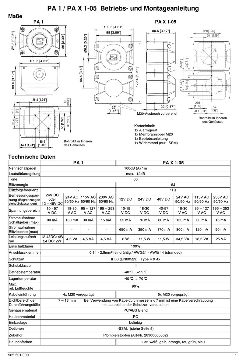
Pfannenberg
Pfannenberg PA X 1-05 Assembly instructions
Pfannenberg
Pfannenberg PY X-S-05 Assembly instructions
Pfannenberg
Pfannenberg BE BG10D-P Series User manual
