2
TABLE OF CONTENTS
Installation Instructions............................................................................................................................................... 3
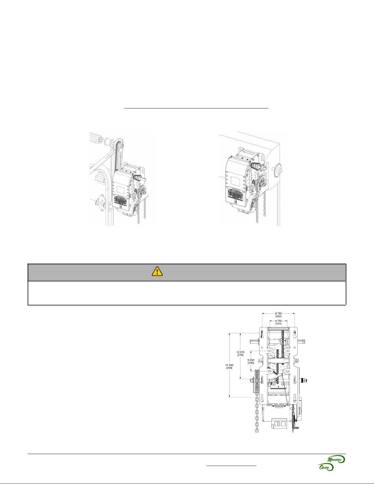
1 General Specifications and Dimensions.........................................................................................................................................................4
2 Door & Operator Hardware...............................................................................................................................................................................5
2.1 Delivery of Operator..................................................................................................................................................................................5
2.2 Hardware Supplied....................................................................................................................................................................................5
3 Operator Installation..........................................................................................................................................................................................6
3.1 Operator Mounting Options.......................................................................................................................................................................6
3.2 Operator Mounting Holes..........................................................................................................................................................................6
3.3 Sprockets, Spreader Bar and Drive Chain Installation.............................................................................................................................7
4 Operator Control Box........................................................................................................................................................................................8
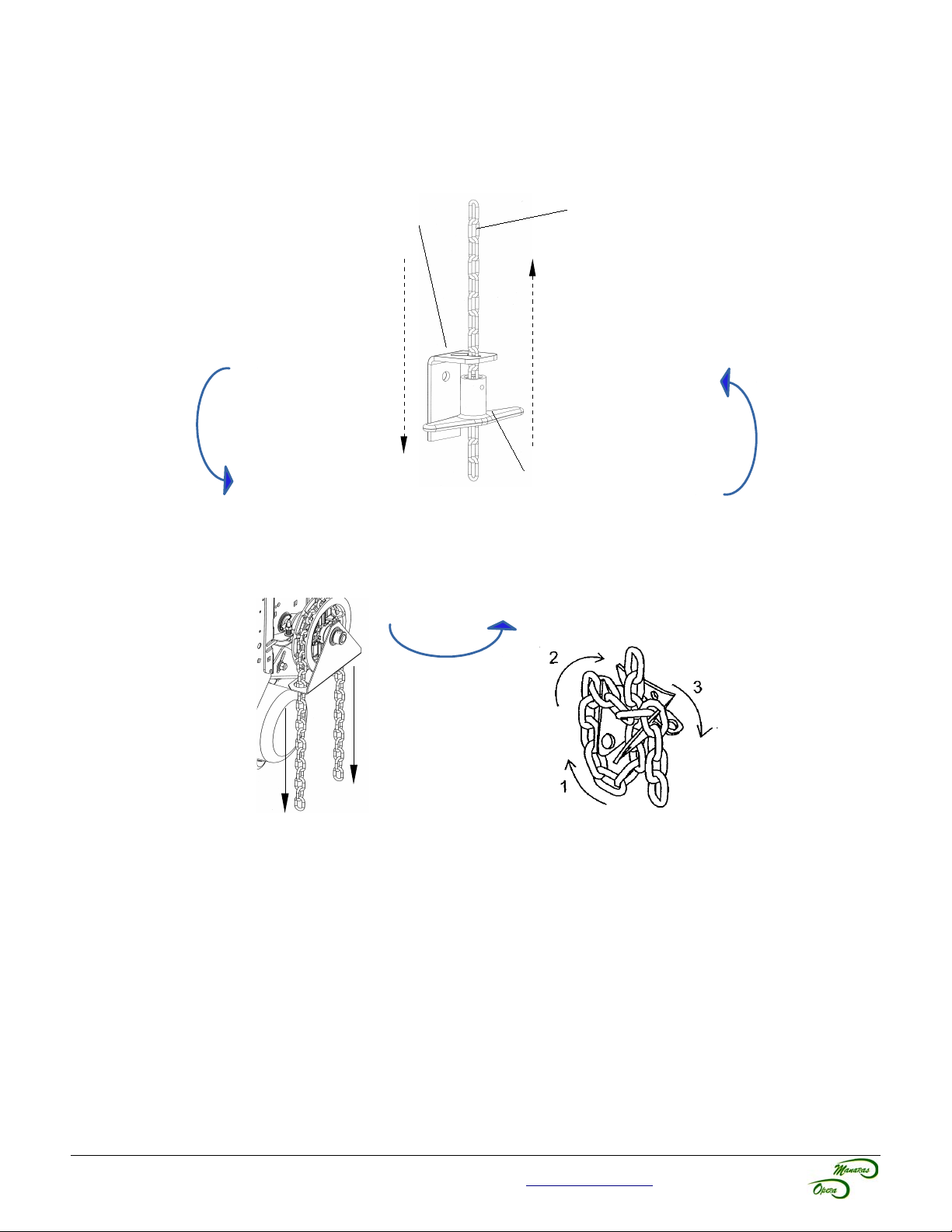
5 Manual Hand Chain and Disconnect Chain.....................................................................................................................................................9
5.1 Installation.................................................................................................................................................................................................9
5.2 Operating Mode......................................................................................................................................................................................10
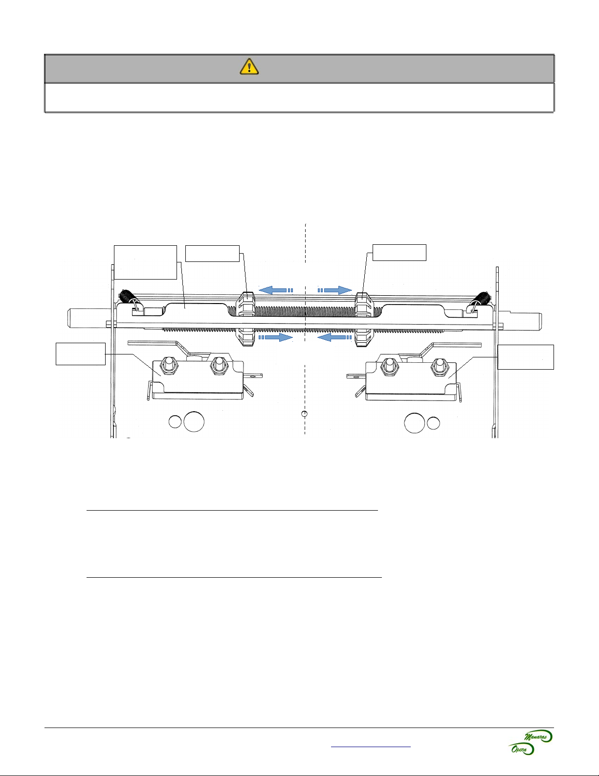
6 Limit Switches & Limit Cams: Adjustment & unctionality.........................................................................................................................11
6.1 Limit Switch Adjustments: Open and Close Cam Settings.....................................................................................................................11
6.2 Limit Switch Functionality........................................................................................................................................................................11
6.3 Limit Switch Adjustment Using Manual Hand Chain if applicable)........................................................................................................12
6.4 Limit Switch Adjustment Without Manual Hand Chain if applicable).....................................................................................................12
7 Electrical Wiring...............................................................................................................................................................................................13
7.1 Low Voltage Controls) and High Voltage Power) Connections............................................................................................................14
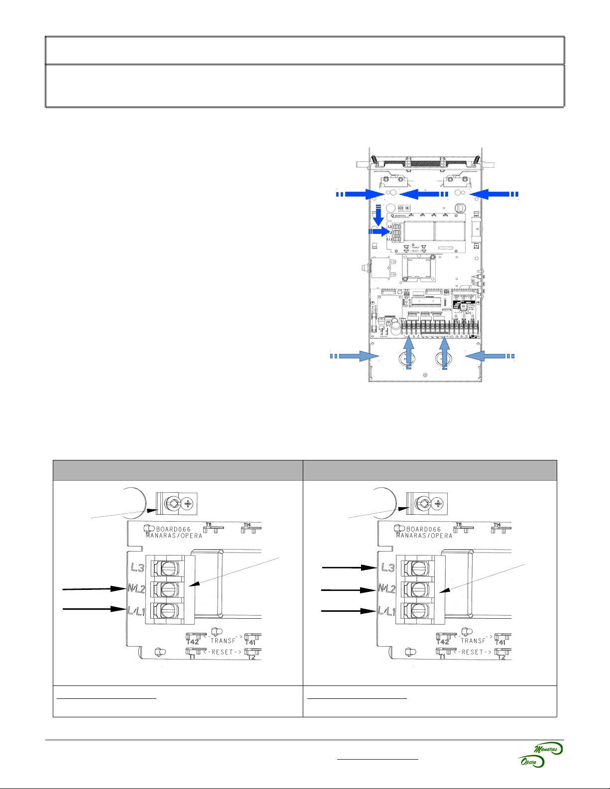
7.2 Main Power Supply Connection..............................................................................................................................................................14
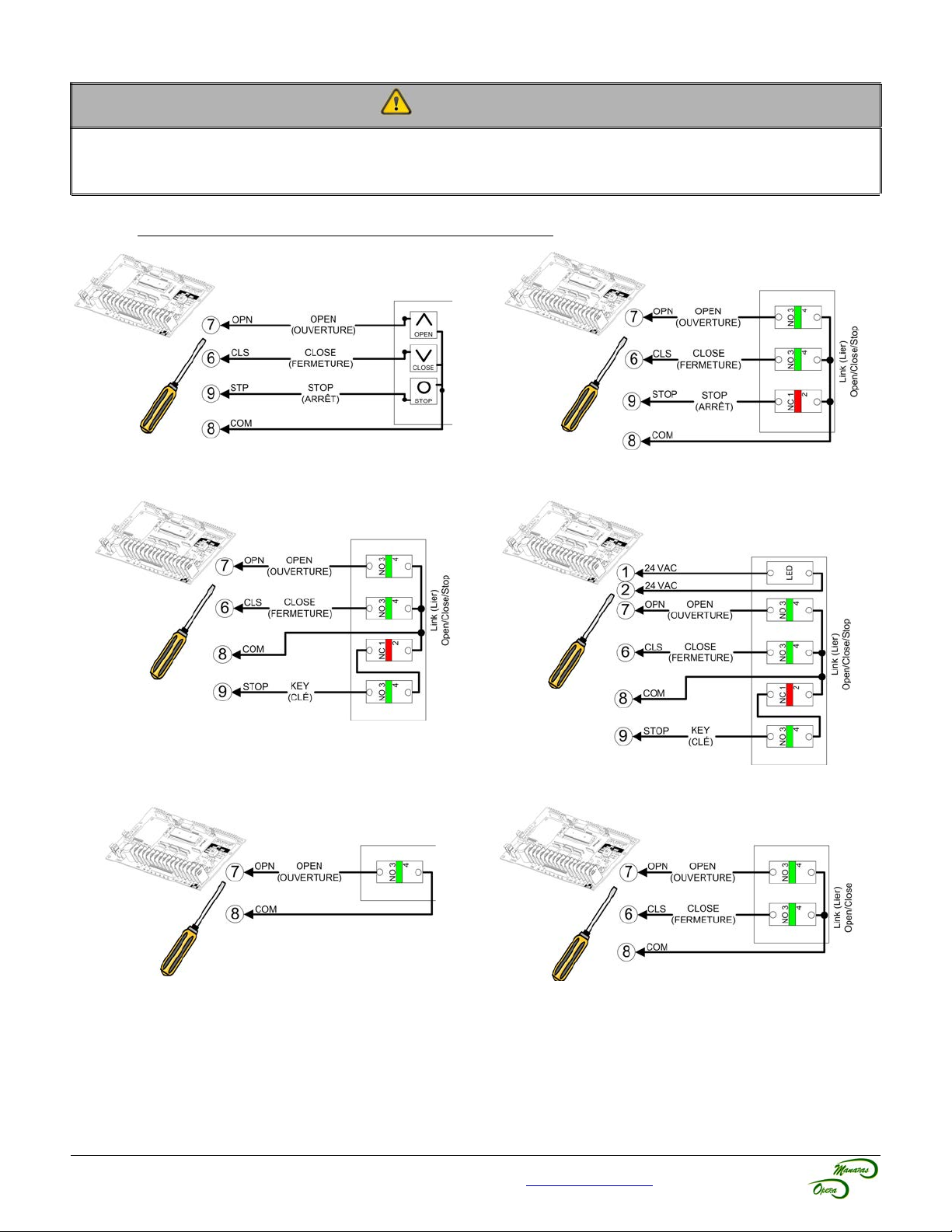
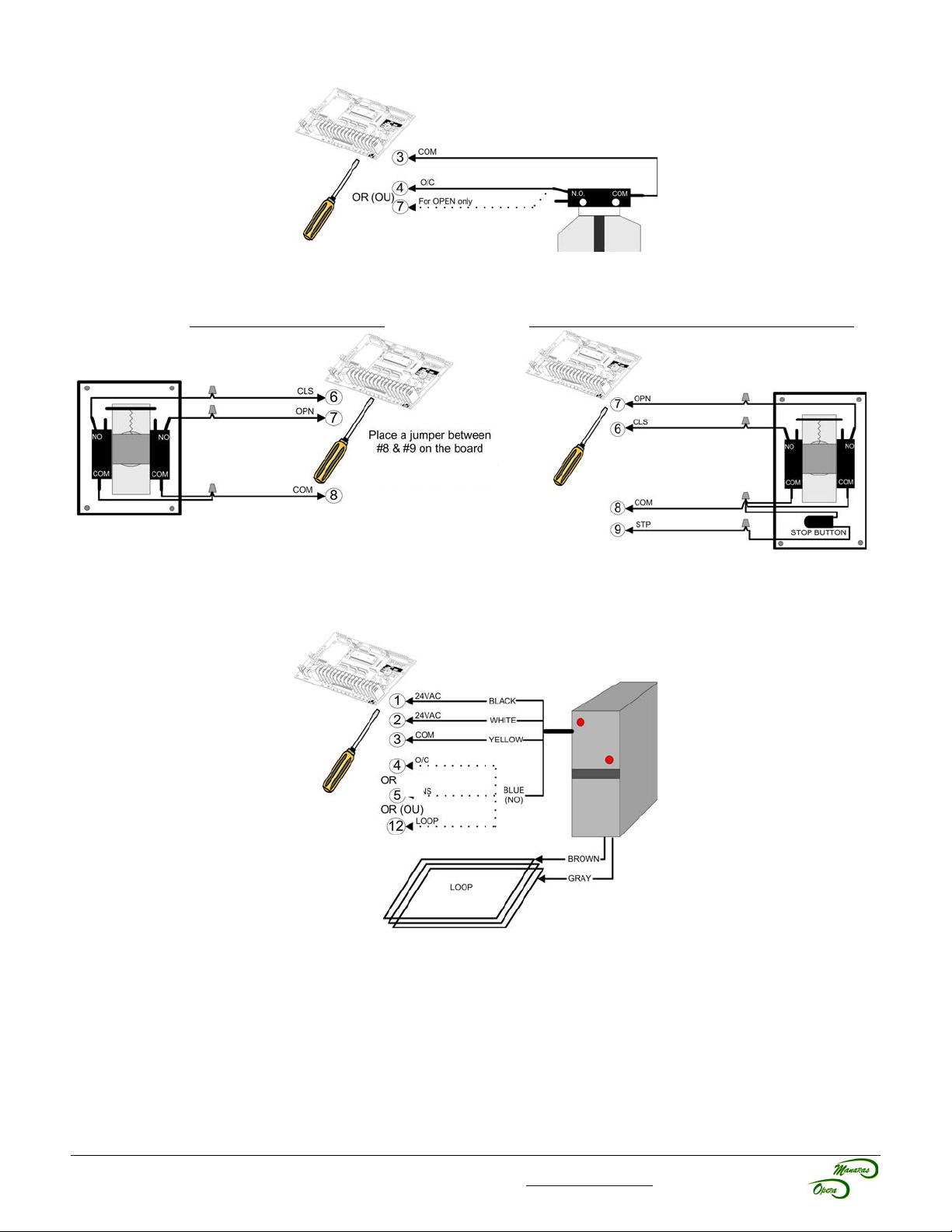
7.3 Push-Button Control Station Connection................................................................................................................................................15
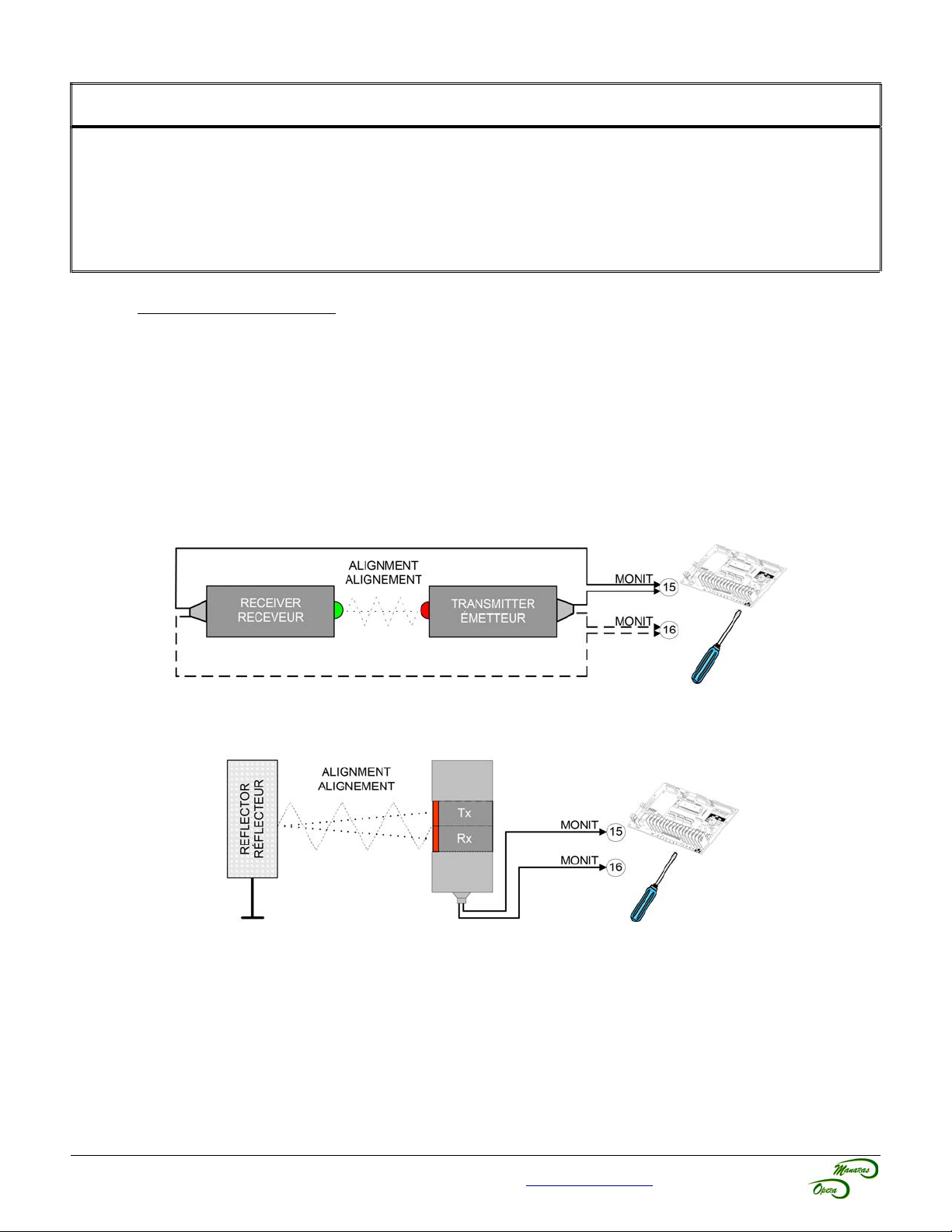
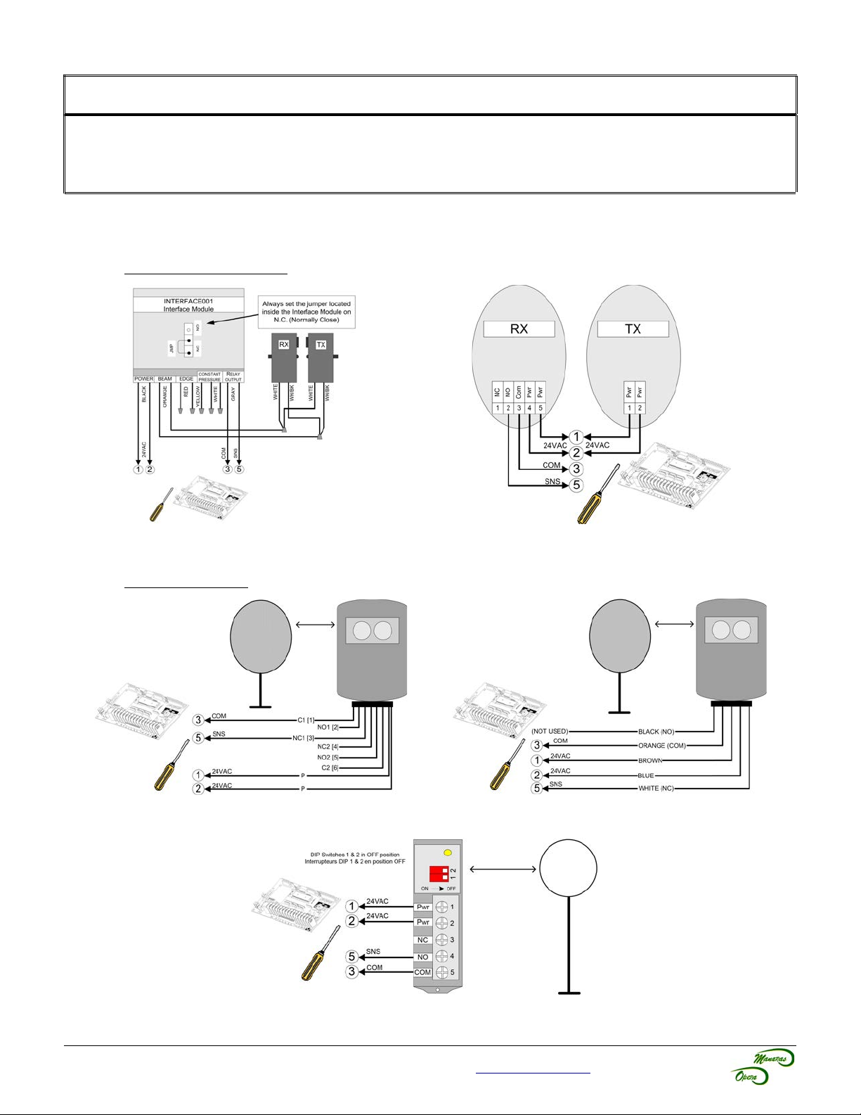
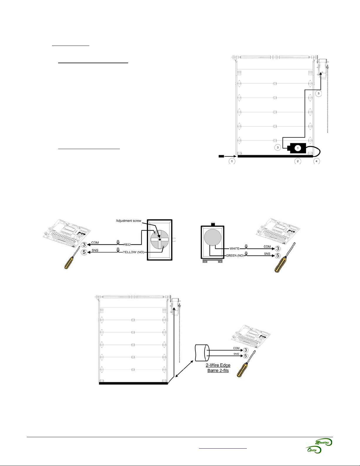
7.4 Monitored External Entrapment Protection Device Connection.............................................................................................................16
7.5 Optional Accessory Connections............................................................................................................................................................18
8 Electronic Control Board (ECB) – BOARD 070M..........................................................................................................................................21
8.1 General Layout........................................................................................................................................................................................21
8.2 On-Board LED Monitoring Status...........................................................................................................................................................22
8.3 Electronic Control Board ECB) Programming.......................................................................................................................................24
9 On-Board Radio Receiver...............................................................................................................................................................................28
9.1 Radio Receiver Components and Compatible Transmitting Devices.....................................................................................................28
9.2 On-Board Radio Receiver Programming Instructions............................................................................................................................28
9.3 Optional External Radio Receivers Ordered Separately)......................................................................................................................28
9.4 Radio Control Functions – 1 and 3-Button Transmitters.........................................................................................................................29
10 Operator Start-up.............................................................................................................................................................................................31
11 Clutch Adjustment...........................................................................................................................................................................................32
User Instructions........................................................................................................................................................ 33
1 Operation Instructions.....................................................................................................................................................................................33
2 Quick ix Instructions.....................................................................................................................................................................................34
Maintenance Instructions........................................................................................................................................... 35
1 Preventative Maintenance Schedule..............................................................................................................................................................35
1.1 Mechanical Inspection.............................................................................................................................................................................35
1.2 Electrical Inspection................................................................................................................................................................................36
1.3 Band Brake Maintenance........................................................................................................................................................................37
2 Troubleshooting Guide....................................................................................................................................................................................39
3 Electrical Drawings..........................................................................................................................................................................................41
3.1 1 Phase Operator with BOARD 070M....................................................................................................................................................41
3.2 3 Phase Operator with BOARD 070M....................................................................................................................................................42
3.3 External Wiring with BOARD 070M........................................................................................................................................................43
4 Mechanical Exploded Views and Replacement Components.....................................................................................................................44
4.1 MSJ General View...................................................................................................................................................................................44
4.2 MSJ Frame Assembly View....................................................................................................................................................................45
4.3 Opera Brake BRAKE 013).....................................................................................................................................................................46
4.4 Opera Control Box with BOARD 070......................................................................................................................................................47
4.5 Replacement Motors, Transformers, Solenoids and Resets..................................................................................................................48
Notes............................................................................................................................................................................ 49
Warranty...................................................................................................................................................................... 51
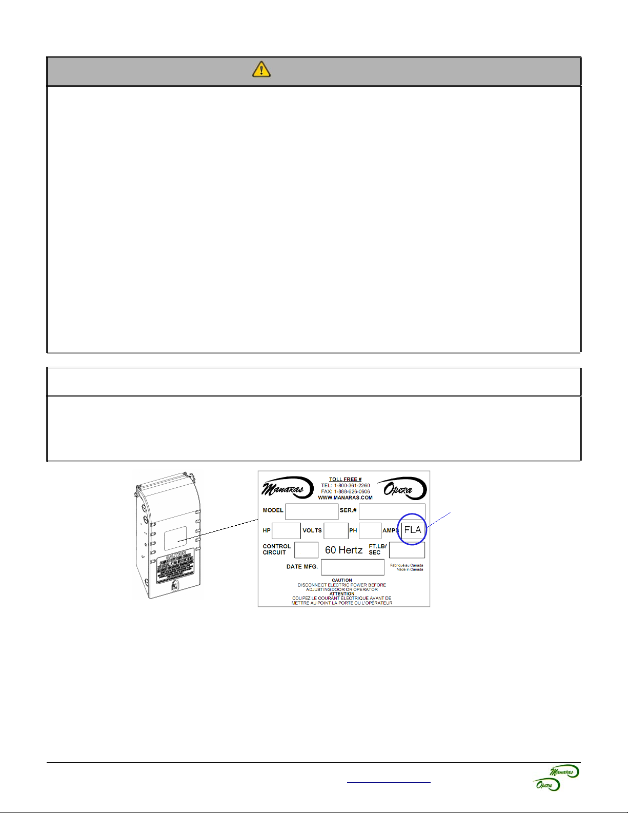
For technical support, please call 1-800-361-2260 or visit www.manaras.com for more information