M&C SP Series User manual

Electrically Heated Sample Probe Tube
Series SP®
SP 30-H../EX2
for Operation in Ex-Zone 2
Instruction Manual
Version 1.02.00

2 SP30-H../EX2 | 1.02.00 www.mc-techgroup.com
Dear customer,
Thank you for buying our product. In this manual you will find all necessary information about this M&C
product. The information in the manual is fast and easy to find, so you can start using your M&C prod-
uct right after you have read the manual.
If you have any question regarding the product or the application, please don’t hesitate to contact M&C
or your M&C authorized distributor. You will find all the addresses in the appendix of this instruction
manual.
For additional information about our products, please go to M&C’s website www.mc-techgroup.com.
There you can find the data sheets and manuals of our products in German and English.
Disclaimer
This instruction manual does not claim to be complete and it may be
subject to technical modifications..
© 10/2018 M&C TechGroup Germany GmbH. The reproduction of this
instruction manual as well as parts of the content are not permitted and
are subject to approval by M&C TechGroup.
Version: 1.02.00

www.mc-techgroup.com SP30-H../EX2 | 1.02.00 3
Content
1General information ................................................................................................................... 4
2Declaration of conformity.......................................................................................................... 4
3Electrical standards ................................................................................................................... 5
4Safety instructions..................................................................................................................... 5
5Information and safety instructions for using the tube in hazardous areas .......................... 6
6Warranty...................................................................................................................................... 6
7Used terms and signal indications............................................................................................ 7
8Application.................................................................................................................................. 8
9Description ................................................................................................................................. 8
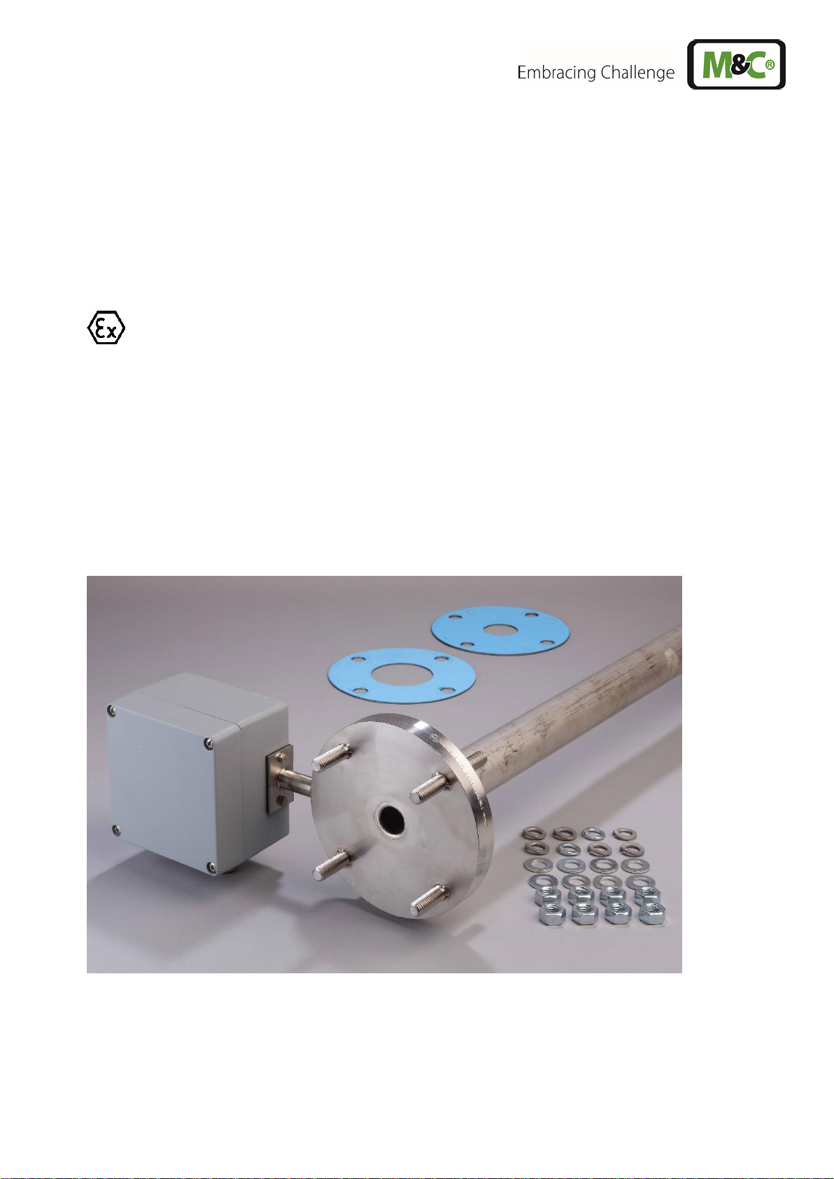
9.1 Heated sample tube SP30-H../EX2 and SP30-H1.1-V/EX2 .................................................. 8
9.2 Temperature controller ......................................................................................................... 9
10 Technical Data.......................................................................................................................... 10
11 Preparation for Installation...................................................................................................... 11
12 Mounting................................................................................................................................... 11
13 Electrical connections ............................................................................................................. 12
13.1 Electrical connection of the heated sample tube................................................................. 13
14 Starting...................................................................................................................................... 14
15 Maintenance ............................................................................................................................. 15
16 Cleaning.................................................................................................................................... 15
List of illustrations
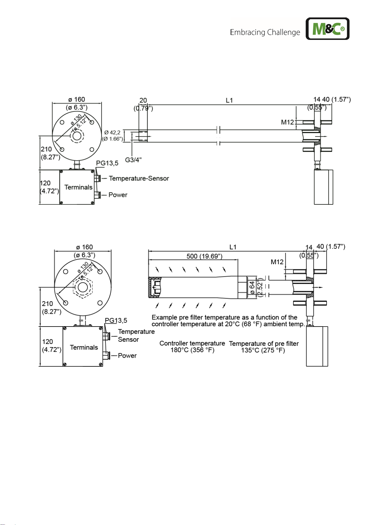
Figure 1 Dimensions SP30-H../EX2....................................................................................... 9
Figure 2 SP30-H1.1-V/EX2.................................................................................................... 9
Figure 3 Mounting of the heated sample tube SP30-H../EX2............................................... 12

4 SP30-H../EX2 | 1.02.00 www.mc-techgroup.com
Head Office
M&C TechGroup Germany GmbH Rehhecke 79 40885 Ratingen Germany
Telephone: 02102 / 935 - 0
Fax: 02102 / 935 - 111
E - mail: info@mc-techgroup.com
www.mc-techgroup.com
1 GENERAL INFORMATION
The product described in this instruction manual has been built and tested in our production facility.
All M&C products are packed to be shipped safely. To ensure the safe operation and to maintain the
safe condition, all instructions and regulations stated in this instruction manual need to be followed. This
instruction manual includes all information regarding proper transportation, storage, installation,
operation and maintenance of this product by qualified personnel.
Follow all instructions and warnings closely.
Read this manual carefully before commissioning and operating the device. If you have any questions
regarding the product or the application, please don’t hesitate to contact M&C or your M&C authorized
distributor.
2 DECLARATION OF CONFORMITY
CE - Certification
The product described in this operating manual complies with the following EU directives:
ATEX-Directive
The product described in this manual is produced in accordance with the EU directive for devices and
protection systems for appropriate use in hazardous areas 2014/34/EU appendix II.
EMC-Instruction
The requirements of the EU directive 2014/30/EU “Electromagnetic compatibility“ are met.
Low Voltage Directive
The requirement of the EU directive 2014/35/EU “Low Voltage Directive“ are met.
The compliance with this EU directive has been examined according to DIN EN 61010.
Declaration of conformity
The EU Declaration of conformity can be downloaded from the M&C homepage or directly requested
from M&C.

www.mc-techgroup.com SP30-H../EX2 | 1.02.00 5
3 ELECTRICAL STANDARDS
The electrical standard of electrical equipment corresponds to the safety regulations concerning the EN
60079-15, EN 61010 and the directive 2014/34/EU (equipment group 3 in hazardous areas);
Producer : M&C TechGroup Germany GmbH
Rehhecke 79
40885 Ratingen
Germany
4 SAFETY INSTRUCTIONS
Follow these basic safety precautions during installation, commissioning and operation of the
device:
Read this instruction manual before commissioning and operating the product. Please make sure to
follow all warnings and safety instructions.
Work on electrical equipment is only to be carried out by trained specialists as per the regulations
currently in force.
Attention must be paid to the requirements of VDE 0100 when setting high-power electrical units with
nominal voltages of up to 1000V, together with the associated standards and stipulations.
For use in hazardous area observe the relevant national and international instructions and regulations.
Check the details on the type plate to ensure that the equipment is connected up to the correct mains
voltage.
Protection against touching dangerously high electrical voltages. Before opening theequipment, it must
be switched and hold no voltages. This also applies to any external control circuits that are connected.
The equipment is only to be set within the permitted range of temperatures and pressures.
Check that the location is weather-protected. It should not be subjected to either direct rain or moisture.
Installation, maintenance, inspections and any repairs of the devices must be carried out only by
qualified skilled personnel in compliance with the current regulations.

6 SP30-H../EX2 | 1.02.00 www.mc-techgroup.com
5 INFORMATION AND SAFETY INSTRUCTIONS FOR USING THE TUBE IN
HAZARDOUS AREAS
The electrically heated tube is suitable for using in hazardous area category 3G.
The explosion proof protection is:
II 3G Ex nA IIC temperature class T5 to T2 (temperature class corresponding to your order).
Installation and operation have to be done corresponding to the
manual. Only in this case the reliability of the operation in the
hazardous area can be guaranteed.
All changes of the standard configuration with parts which are not specified or approved by M&C as
well as repair and service with not specified parts means a loss of the Ex-certificate.
In case of doubt please turn directly to M&C respectively to your M&C franchised dealer.
6 WARRANTY
In case of a device failure, please contact immediately M&C or your M&C authorized distributor.
We have a warranty period of 12 months from the delivery date. The warranty covers only appropriately
used products and does not cover the consumable parts. Please find the complete warranty conditions
in our terms and conditions.
The warranty includes a free-of-charge repair in our production facility or the free replacement of the
device. If you return a device to M&C, please be sure that it is properly packaged and shipped with
protective packaging. The repaired or replaced device will be shipped free of delivery charges to the
point of use.

www.mc-techgroup.com SP30-H../EX2 | 1.02.00 7
7 USED TERMS AND SIGNAL INDICATIONS
DANGER!
This means that death, severe physical injuries and/or important
material damages will occur in case the respective safety measures
are not fulfilled.
W ARNING!
This means that death, severe physical injuries and/or important
material damages may occur in case the respective safety measures
are not fulfilled.
CAUTION!
This means that minor physical injuries may occur in case the
respective safety measures are not fulfilled.
CAUTION!
Without the warning triangle meansthat a material damage may occur
in case the respective safety measures are not met.
ATTE N TION!
This means that an unintentional situation or an unintentional status
may occur in case the respective note is not respected.
NOTE!
These are important information about the product or parts of the
operating manual which require user’s attention.
QUALIFIED PERSONNEL
‘Qualified personnel’ are experts who are familiar with the installation,
commissioning, maintenance and operation of these types of
products. The following knowledge is at least required for the work:
•Instructed person in EX-protection
•Trained person in the electrotechnical field
•Detailed knowledge of the manual and the applicable safety
regulations
These are important information about the product or parts of the
instruction manual referring to operating in hazardous areas.
High voltages!
Protect yourself and others against damages which might be caused
by high voltages.
Hot surface!
Contact may cause burn! Do not touch!

8 SP30-H../EX2 | 1.02.00 www.mc-techgroup.com
Wear protective gloves!
Working with chemicals, sharpe objects or extremly high
temperatures requires wearing protective gloves.
Wear safety glasses!
Protect your eyes while working with chemicals or sharpe objects.
Wear safety glasses to avoid getting something in your eyes.
Wear protective clothes!
Working with chemicals, sharpe objects or extremly high
temperatures requires wearing protective clothes.
8 APPLICATION
The electrically heated sample tube SP30-H../EX2 is used wherever cooling down or falling below the
dew point, e.g. SP3200-H, is to be avoided during gas sampling from the sampling point to the heated
gas sampling probe.
In dust-laden processes which tend to fall below the dew point in the extraction area during operation or
when the system is at a standstill, it may be advisable to use the electrically heated sample tube SP30-
H1.1-V/EX2 with heated in-situ pre-filter V20-2/30. This prevents premature clogging or destruction.
9 DESCRIPTION
9.1 HEATED SAMPLE TUBE SP30-H../EX2 AND SP30-H1.1-V/EX2
The heated sample tubes SP30-H../EX2 and SP30-H1.1-V/EX2 can be
installed in hazardous areas of zone 2.
The electrically heated M&C sample tube SP30-H../EX2 is available in 0.6 m [23.62”] and 1 m (39.37“]
length (L1 in Fig. 1 and 2). Other length on request.
With a mounting flange with 4 welded screws the heated sample tube SP30-H../EX2 can be easily fixed
both to the flange at the sample point and the probe head e.g. SP3200-H.
The heated sample tubes SP30-H../EX2 are equipped with a G3/4"i thread connector at the tube end.
This enables fixing a standard non heated sample tube or pre-filter to the heated insitu tube.
The electrical cartridge heater is located inside a double tube system, completely separated from the
process. At the version SP30-H1.1-V/EX2 the included large pre-filter V20-2/30 is heated up with the
sample tube.
The tube versions SP30-H../EX2 have an internal diameter of 22 mm.

www.mc-techgroup.com SP30-H../EX2 | 1.02.00 9
The internal diameter of the version SP30-H1.1-V/EX2 is reduced to 6 mm to optimize the tube dead
volume.
The sample tubes SP30-H1.1/EX2 and SP30-H1.1-V/EX2 have a temperature sensor Fe-CuNi for max.
320 °C [608 °F] operating temperature.
Figure 1 Dimensions SP30-H../EX2
Figure 2 SP30-H1.1-V/EX2
9.2 TEMPERATURE CONTROLLER
The temperature control must be mounted externally.
The function and correctness of the temperature control is the responsibility of the installer and operator.

10 SP30-H../EX2 | 1.02.00 www.mc-techgroup.com
10 TECHNICAL DATA
Serie SP®
SP30-H1.1/EX2
SP30-H2/EX2
SP30-H1.1-V/EX2
Temperature sensor
Fe-CuNi
PT100 2-wire
Fe-CuNi
Temperature controller
external
Probe tube length L1
max. 1 m [39.37“]
Sample temperature
depending on the temperature class (see table temperature class).
Please specify with order.
Operating temperature
depending on the temperature class (see table temperature class).
Please specify with order.
Pre-filter
optional
optional
V20-2/30 insitu filter
length 520 mm,
60 mm, filter
porosity 2 μm,
integrated and
heated
Sample gas inlet
connection
G3/4"i DIN ISO 228/1
pre-filter with G1 1/2"i
DIN ISO 228/1
Dust loading
max. 2 g/m3
>2 g/m3
Probe tube volume
380 ml per meter
420 ml
Sample pressure
max. 5 bar g
Ambient temperature
-20 to +70 °C [-4 to 158 °F]
Storage temperature
-20 to +70 °C [-4 to 158 °F]
Ready for operation
2 h
Power supply
230 V 50/60 Hz or 115 V 50/60 Hz
Heating capacity
0.6 m [23.62”]: 600 W, 1 m [39.37“]: 800 W, (other length/capacities on
request)
Electrical connections
terminals, max. 4 mm2, 2 x PG13,5 cable gland, terminal range 6-12 mm
Electrical standard
EN 61010, EN 60519-1
Degree of protection
IP54 EN 60529
Ex-marking
II 3 G Ex nA II T5 to T2 see table temperature class
Mounting flange
DN65 PN6, Form B with 4 welded screws on both sides M12 x 40 mm
Material of parts in
contact with the sample
stainless steel 904L
stainless steel 904L,
SS316Ti/SS316
Temperature class
Operating/sampling temperature
°C [°F]
Limiter
°C [°F]
T2
280 [536 °F]
290 [554 °F]
T3
185 [365 °F]
190 [374 °F]
T4
120 [248 °F]
125 [257 °F]
T5
85 [185 °F]
90 [194 °F]

www.mc-techgroup.com SP30-H../EX2 | 1.02.00 11
11 PREPARATION FOR INSTALLATION
Select the optimum sampling point according to the generally applicable guidelines or consult the
responsible authorities.
Locate the sampling point in such a way that there is adequate space for inserting and removing the
probe and pay attention to the insertion length of the probe tube.
Make certain that the probe is easily accessible so that you can carry out any subsequent maintenance
work without trouble.
If the ambient temperature in the area of the connections is > 70°C [> 158 °F] as a result of radiated
heat, then a radiated-heat deflector must be mounted to protect the probe.
The connection's mounting flange connection should comply with DN65 PN6. If other connection sizes
are required, the stud bolts of the heated sample tube can be arranged accordingly as option.
The necessary minimum flange size and the minimum connection diameter depends on the diameter of
the probe tube or pre-filter used.
Before mounting, the probe must be adjusted to the existing operating conditions.
The existing operational parameters are to be checked accordingly prior to commencing mounting work
(see also technical data, chapter 10):
Under / over pressure situation
mbar
bar
Process temperature
°C Min.
°C Max.
Dust loading
g/m³
Dust composition - grain size
µm
Gas composition
corrosive
toxic
explosive
Which parameters should be measured,
e.g. O2, CO, SO2, NOX,...,
Vol.%
mg/Nm³
ppm
Required amount of gas
l/h
Min.
l/h
Max.
Necessary T90 time
sec.
12 MOUNTING
W ARNING!
The permitted ambient temperature for the connection box of the
sample tubes SP30-H../EX2 and SP30-H1.1-V/EX2 is -20 to +70°C [-4
to 158 °F].
•Put flange sealings on the threaded bolts of the heated sample tube.
•Screw together gas sample probe with threaded bolts of the heated sample tube.
•Screw together gas sample probe at the sampling connection piece with threaded bolts on the
process side of the heated sample tube.

12 SP30-H../EX2 | 1.02.00 www.mc-techgroup.com
Figure 3 Mounting of the heated sample tube SP30-H../EX2
13 ELECTRICAL CONNECTIONS
WARNI NG!
When connecting the equipment, please ensure that the supply
voltage is identical with the information provided on the model type
plate.
NOTE!
Attention must be paid to the requirements of IEC 364 (DIN VDE
0100) when setting high-power electrical units with nominal voltages
of up to 1000 V, together with the associated standards and
stipulations.
In any case we recommend the use of temperature resistant cable!
A main switch and matching fuse must be provided externally!
The main circuit must be equipped with a fuse corresponding to the
nominal current (over current protection); for electrical details see
technical data.
It is recommended to use the low temperature alarm. In case of an
alarm the flow can be stopped and the components downstream the
probe are safe for demage.
Function and correctness of the temperature control (temperature
class) is in the sole responsibility of the installer and operator.

www.mc-techgroup.com SP30-H../EX2 | 1.02.00 13
13.1 ELECTRICAL CONNECTION OF THE HEATED SAMPLE TUBE
WARNING!
The used cables for the connection of the heating must have an
outer diameter of 6-12 mm corresponding to the clamping range of
the cable glands!
W ARNING!
The max. admissible ambient temperature for the connection box
of the sample tubes SP30-H../EX2 and SP30-H1.1-V/EX2 is +70 °C
[158 °F].
Temperature resistant cable have to be used corresponding to the
max. temperature at the installation site.
•Remove lid of the connection box. In the lid there is also the electrical wiring plan.
•Insert the power cable (min. 3 x 1.5 mm2) coming from the external temperature controller
through the cable gland and connect it at the corresponding terminals 6, 7 and 8.
•Insert the temperature sensor cable through the other cable gland and connect it to the terminals
2, 3 and 4.
•Remount lid.
Function and correctness of the temperature control (temperature
class) is in the sole responsibility of the installer and operator.
Valid from serial number 1810XXXX

14 SP30-H../EX2 | 1.02.00 www.mc-techgroup.com
14 STARTING
WARNI NG!
Before starting up check whether the mains power supply voltage
corresponds with the information stated on the nameplate.
WARNI NG!
Start up only the built-in heated probe tube because otherwise
there is a risk of burning!
WARNI NG!
Check whether the housing of the heating controller and the
connection box of the heated sample tube are earthed. Earth
resistance < 0.3 Ohm.
•Switch on mains power supply.
•Then inner temperature of the sample tube has to be measured during the heat-up phase.
The maximum temperature reached is the value for the temperature class. This has to be taken
from the table below. Adjust desired temperature via controller.
Function and correctness of the temperature control (temperature
class) is in the sole responsibility of the installer and operator.
•The nameplate contains no information about the temperature class because this is determined
by the temperature controller only.
Temperature class
Operating/sampling temperature
°C
Limiter
°C
T2
280 [536 °F]
290 [554 °F]
T3
185 [365 °F]
190 [374 °F]
T4
120 [248 °F]
125 [257 °F]
T5
85 [185 °F]
90 [194 °F]

www.mc-techgroup.com SP30-H../EX2 | 1.02.00 15
15 MAINTENANCE
W ARNING!
The safety instructions specific to the plant and process are to be
consulted prior to any maintenance work!
DANGER!
Caution, danger of explosion!
Under voltage do not take the device off the mains!
WARNI NG!
When working during operation:
High surface temperatures!
Touching the surfaces can result in burns. Wear protective gloves
and protect against unauthorized access!
WARNI NG!
Work on the gas sample probe may only be carried out when the
environment has beendeclared an explosion-free zone, i.e. it is free
of explosive atmospheres.
The requirements of VDE 0100 and its associated standards and
regulations must be observed when erecting and servicing high-
voltage power installations with rated voltages to 1000V!
16 CLEANING
NOTE!
In case of external contamination of the connection box and the
temperature controller housing clean these onlywith a clothwetted
with soapy water.

16 SP30-H../EX2 | 1.02.00 www.mc-techgroup.com
Other manuals for SP Series
9
This manual suits for next models
1
Table of contents
Other M&C Industrial Equipment manuals
Popular Industrial Equipment manuals by other brands

Smart Storm
Smart Storm USI HYDROCELL 4 instruction manual

SCM
SCM CU 300C instruction manual

ABB
ABB HT842192 Operation manual

AC Air Technology
AC Air Technology AC Tracktech T-MINI with Grab Cradle instruction manual

Balluff
Balluff BIC 1B0-IT1A7-Q40KFU-SM4A4A user guide

Dongguan Xin Bao Instrument
Dongguan Xin Bao Instrument XB-OTS-2T Operation manual