M&G Duravent Duratech Canada HT Owner's manual

PIDURATECH REV. 2 07/2013
DURATECH CANADA (DTC)
Factory-built CHIMNEY
5”, 6”, 7”, 8” & 10” dia.
TYPE HT
INSTALLATION
AND
OPERATION
INSTRUCTIONS
Read these instructions and keep them for future reference
Listed: CAN/ULC-S629 (6’’,7’’,8’’ only)
CAN /ULC-S604
UL-103HT
Duravent
www.duravent.com
SUMMARY
OUR PRODUCTS LIVE UP TO OUR NAME, WARNING. . . . . . . . . . . . . . . 2
KEEP YOUR CHIMNEY CLEAN, SIZING CHART . . . . . . . . . . . . . . . . . . . 3
GENERAL INSTALLATION NOTES. . . . . . . . . . . . . . . . . . . . . . . . . . . . . . . 4
INTERIOR STRAIGHT INSTALLATION WITH MULTIPLE FLOORS . . . . . . . 5
INTERIOR INSTALLATION WITH CATHEDRAL CEILING . . . . . . . . . . . . . . 7
OFFSET INSTALLATION . . . . . . . . . . . . . . . . . . . . . . . . . . . . . . . . . . 8-9
EXTERIOR INSTALLATION . . . . . . . . . . . . . . . . . . . . . . . . . . . . . . 10-11
INTERIOR INSTALLATION ON A FURNACE & WATER HEATER . . . . . . . . 12
SPECIALIZED COMPONENTS . . . . . . . . . . . . . . . . . . . . . . . . . . . . . . 13
WARRANTY. . . . . . . . . . . . . . . . . . . . . . . . . . . . . . . . . . . . . . . . . . 15

2
Wood
Type
Ability To Create
Long Lasting Coals
Sparks Fragrance Heating
Qualities
Black Locust Excellent Very Few Slight Excellent
Maple Excellent Few Good Excellent
Oak Excellent Few Fair Excellent
Hickory Excellent Moderate Slight Excellent
Beech Good Few Slight Excellent
Cherry Excellent Few Excellent Good
Apple Excellent Few Excellent Good
Elm Good Very Few Fair Good
Ash Good Few Slight Good
Birch Good Moderate Slight Good
Hemlock Low Many Good Fair
Pine Poor Moderate Good Fair
Cedar Poor Many Good Fair
BURNING SMART
How you burn wood in your stove or fireplace directly affects the forma-
tion of creosote. Smaller, hotter fires are better than large, smouldering
ones. Fast, effective start ups are important, as is the moisture content
of the wood. Ideally, you should use seasoned wood with a moisture
content of 20 25%. A surface thermometer is an excellent investment.
Properly seasoned wood can produce 8,600 BTUs per pound.
APPLICATIONS
DURATECH CANADA (DTC) chimney has been designed for use with wood,
gas, oil and coal in residential, commercial and industrial applications.
DURATECH CANADA (DTC) has been listed to ULC-S629 , 2100 F in
diameter 6,7 and 8 inches for wood/coal application . Note that for
interior enclosed installation, premium shield are required around
the chimney. Refer to specific Canadian installation section for proper
installation.
DURATECH CANADA (DTC) is also designed for use with gas or oil
fired heating appliances such as furnace, hot water heaters and other
appliances, as per ULC-S604 standards in diameter 5 to 10 inches.
In these types of installations, no premium shields are required even
where the chimney is enclosed.
If you are planning to install a wood stove, we recommend that you:
1. Choose a stove that bears the label of a testing laboratory (such as
UL, CSA, WH, ULC or ICBO).
2. Choose the right size stove. Do not buy one larger than you need.
3. Connect only one appliance to a chimney.
4. Never overfire your stove. If any part of the stove or stove pipe is
glowing red, then you are overfiring. Immediately close the stove’s
dampers until the system cools. The high temperature caused by
overfiring can permanently damage the stove and stove pipe and may
overheat nearby combustible walls and furniture.
5. Install the stove and stove pipe as described in the installation instruc-
tions accompanying the stove. Be certain to maintain the required
clearances to combustible construction.
6. Keep your flue gases between 300°F and 500°F. This will maximize
efficiency while minimizing condensation and creosote formation. Do
not fill your stove with wood and allow it to smoulder for 8 to 10 hours.
This condition produces large amounts of creosote in the chimney.
7. Do not burn sea driftwood or treated wood. These combustibles are
highly corrosive to all types of stainless steel.
FACTORY BUILT FIREPLACE
DURATECH CANADA (DTC) in Canada is also suitable for use with closed
or opened certified fireplaces.
Note that the premium shields are normally not required for factory-
built fireplace installation, including interior chase.
When doing so please refer to the fireplace installation instructions to
install the chimney.
WOOD AND COAL STOVES
OUR PRODUCTS LIVE UP TO OUR NAME
CONGRATULATIONS!
You have just purchased one of the safest chimneys
in North America. Designed with care, using the lat-
est technology, it has been manufactured in accor-
dance with ISO International Standards of Quality.
The chimney is easy to install and all parts of the sys-
tem are built to fit perfectly with each other. If you’re
handy, know how to use a few simple tools and have
some basic carpentry skills, you can install your DU-
RATECH CANADA (DTC) chimney yourself over one
weekend. Or you can hire a professional to do the job.
WARNING
A MAJOR CAUSE OF CHIMNEY-RELATED FIRES IS FAILURE TO MAINTAIN
REQUIRED CLEARANCES (AIR SPACES) TO COMBUSTIBLE MATERIALS.
IT IS OF UTMOST IMPORTANCE THAT THIS CHIMNEY BE INSTALLED
ONLY IN ACCORDANCE WITH THESE INSTRUCTIONS.
RECOMMENDATIONS
Clearance
The clearances stated in this guide are minimum requirements: if more
space is available, use it. Minimum clearances mean leaving unobstruct-
ed air space. Do not fill these spaces with any material whatsoever, es-
pecially not insulating material. If you insulate your attic later, be sure to
maintain the necessary clearance.
Inspection
Contact local building or fire officials about restrictions, installation in-
spection and permit that may be required in your area.
Replacement Parts
If a component of your chimney system is damaged it must be replaced
by an identical one from Duravent.
NOT ALL WOOD IS CREATED EQUAL
Some types of wood have greater energy potential than others. Some
logs will give you a hot, crackling fire, others will burn longer and more
evenly. Choose the type of flame you prefer. The following table shows
how different types of wood burn.
Table 1

3
CHIMNEY OPERATION AND MAINTENANCE
KEEP YOUR CHIMNEY CLEAN SIZING CHART
Wood stoves can quickly create large deposits of creosote in the chimney.
Some wood stoves can create enough creosote in two weeks to cause
a chimney fire. When using a wood stove, we recommend that you:
1. Initially inspect the chimney system weekly. From this, you will learn
how often it will be necessary to clean your chimney.
2. The chimney should be inspected at least once every 2 months during
the heating season to determine if a creosote or soot build-up has
occurred: if creosote or soot has accumulated, it should be removed
to reduce the risk of chimney fire.
3. Have your chimney cleaned by a qualified chimney sweep. If you want
to clean your chimney yourself: clean your chimney using plastic,
wood or stainless steel brushes. Do not use a brush that will scratch
the stainless steel interior of your chimney.
4. Do not expect chemical chimney cleaners to keep your chimney clean.
Their use does not negate the necessity of periodically inspecting and
cleaning your chimney.
CHIMNEY FIRES
If you are having a chimney fire, follow these steps:
1. Close all heater doors and combustion air controls. For fireplaces,
block the fireplace opening with a non-combustible material (such as
a steel sheet).
2. Alert your family to the possible danger.
3. If you require assistance, alert your fire department.
4. If possible, use a dry chemical fire extinguisher, baking soda or sand
to control the fire. Do not use water as it may cause a dangerous
steam explosion.
5. Watch for smouldering or fire on combustibles next to the stove,
stove pipe and chimney. Check outside to ensure that sparks and
hot embers coming out of the chimney are not igniting the roof.
6. Do not use the stove again until your chimney and stove pipe have been
inspected by a qualified chimney sweep or Fire Department Inspector.
DURATECH DTC chimney has been designed to withstand the intense
heat of a chimney fire. Nevertheless chimney fires are dangerous
and should be prevented.
BEFORE HIRING A CHIMNEY SWEEP
1. Does the company or individual have adequate liability insurance
in case of damage?
2. How long has the company been in business?
3. Does the company offer current references?
4. Is the company involved in any unresolved disputes?
CHIMNEY-SIZE 5” 6” 7” 8” 10”
OUTSIDE-DIAMETER 7” 8” 9” 10” 12”
HOLE-DIMENSION-REQUIRED
Base-support (DTC-BS) 12-1/8” 12-1/8” 14-3/8” 14-3/8” --
Cathedral support (DTC-RCSC) -- 12-1/8” 14-3/8” 14-3/8” --
Square support (DTC-CS) -- 12-1/8” 14-3/8” 14-3/8” 14-3/8”
Finish support (DTC-FSC) -- 12-1/8” 14-3/8” 14-3/8” --
Firestop (DTC-FS) 11-3/8” 12-3/8” 13-3/8” 14-3/8” 16-3/8”
MAX. LENGTH HEIGHT SUPPORTED **
Base support (DTC-BS) -- 32’ 32’ 32’ 32’
Tee support (DTC-TS) 63’ 63’ 55’ 48’ 39’
Roof support (DTC-RS) 42’ 34’ 27’ 24’ 20’
Radiation Shield Connector
Support (DTC-FRSCS) -- 30' 24’ 21’ --
Cathedral support (DTC-RCSC) -- 75’ 65’ 59’ --
Square support (DTC-CS) -- 60’ 50’ 45’ 35’
Adj. square support
(DTC-CSAS)
27’ 22’ -- -- --
Finish support (DTC-FSC) -- 75’ 65’ 59’ --
Offset support (DTC-RESU) -- 28’ 24’ 20’ 14’
Insulated tee (DTC-TSS) * 63’ 63’ 55’ 50’ 50’
CLEARANCE TO
COMBUSTIBLES
2” 2” 2” 2” 2”
Table 2
* When installed on a concrete footing.
** NOTE: If greater height is required, use additional roof supports at
intervals not exceeding 30’
CHIMNEY
SIZE 5” 6” 7” 8” 10”
ROOF
SLOPE HOLE SIZE
x/12 A B A B A B A B A B
0 11-3/8 11-3/8 12-3/8 12-3/8 13-3/8 13-3/8 14-3/8 14-3/8 16-3/8 16-3/8
2/12 11-3/8 11-1/2 12-3/8 12-1/2 13-3/8 13-1/2 14-3/8 14-9/16 16-3/8 16-19/32
4/12 11-3/8 12 12-3/8 13 13-3/8 14-3/32 14-3/8 15-5/32 16-3/8 17-1/4
6/12 11-3/8 12-11/16 12-3/8 13-13/16 13-3/8 14-15/16 14-3/8 16-3/32 16-3/8 18-5/16
8/12 11-3/8 13-11/16 12-3/8 14-7/8 13-3/8 16-1/16 14-3/8 17-1/4 16-3/8 19-11/16
10/12 11-3/8 14-13/16 12-3/8 16-1/8 13-3/8 17-7/16 14-3/8 18-23/32 16-3/8 21-5/16
12/12 11-3/8 16-1/16 12-3/8 17-1/2 13-3/8 18-29/32 14-3/8 20-11/32 16-3/8 23-5/32
Table 3 - Refer to Figure 1
HOLE SIZE
DOWN
B
ROOF SLOPE
INCHES
SIDES OF HOLE MUST
BE VERTICAL
12 IN
X
ACROSS
SLOPE
A
Figure 1
NOTE: DIAGRAMS & ILLUSTRATIONS ARE NOT TO SCALE.
4
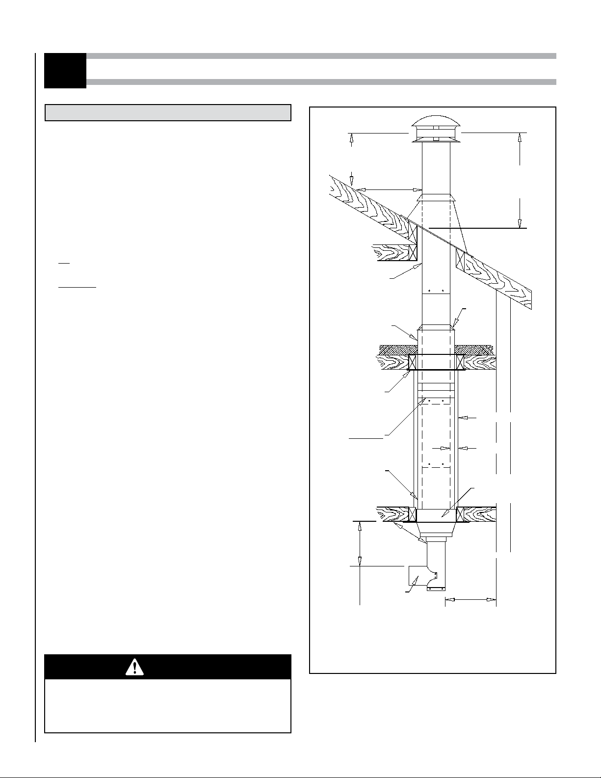
GENERAL INSTALLATION NOTES
INSTALLATION NOTES
1
1. The chimney is intended for use with solid (6’’,7’’,8’’ dia. only) or
liquid and gaseous fuel burning appliances.(all diameters)
Allowable flue gas temperature:
Maximum continuous 540°C (1000°F)
Brief forced firing 760°C (1400°F)
Tested to 1150°C (2100°F) - 30 minutes
2. On wood or coal stove application and in area where the chimney
is completely enclosed, it is required to install Premium shields
(telescopic of flexible) around the chimney and a Radiation shield
connector at the ceiling level.
For venting of gas or oil burning appliances Premium shields are
not required even where the chimney is enclosed.
For factory-built wood burning fireplaces, Premium shields are
usually not required, please follow fireplace installation instruction.
3. The maximum height of chimney supported by the various supports
are outlined on page 3.
4. The supports described in this booklet should only be used with
Duravent model DURATECH CANADA (DTC), 5", 6", 7", 8" and 10"
factory built chimneys.
5. Size the chimney in accordance with the appliance manufacturer's
instructions.
6. When a firestop (DTC-FS , DTC-ISI or DTC-RSCI) needs to be installed,
it is important to follow the opening dimensions for the floor open-
ings prescribed in this manual. This way, the holes left by the folded
positioning tab of the firestop will be blocked by the ceiling.
7. A chimney servicing a fireplace or an incinerator shall not serve any
other appliance.
8. The chimney shall extend at least 3 ft above its point of contact with
the roof and at least 2 ft higher than any wall, roof or adjacent building
within 10 ft of it.
9. The maximum height of unguided chimney above the roof is 5 ft.
10. The clearance between single wall pipe and unprotected combustible
material must not be less than 18" (see national building code and
NFPA 211) except: The distance between the vertical stove pipe and
the ceiling may be less than 18" and will be established by the finish
support.
11. Portions of the chimney which may extend through accessible spaces
shall be enclosed in all cases to avoid personal contact with the chimney
and damage to the chimney. When doing so on woodstove or coal
application, a telescopic or flexible Premium shield must be installed
(see Figure 2). Except for installation in single and two-story family
dwellings, the enclosure must have a fire resistance rating equal to
or greater than that of the floor or roof assemblies through which
they pass.
12. Do not fill the 2" space around the chimney with insulation or any
other material. Insulation placed in this area could cause adjacent
combustibles to overheat.
13. Self tapping screws are not required, but may be used to reinforce
the connection and avoid accidental unlocking of chimney lengths.
2 ft
MIN.
10 ft
3 ft
MIN.
2" MIN.
ENCLOSURE
2" MIN.
7 1/2"
MIN.
BASE TEE
* 18"
MINIMUM
* 18"
MINIMUM
* THE DISTANCE CAN BE REDUCED IF A
LISTED STOVE PIPE IS USED.
Figure 2
WARNING
The clearance between the chimney and combustible
material must not be less than 2", except where
established by the support. Do not fill this area with
insulation.
RADIATION
SHIELD
CONNECTOR
(DTC-RSCI)
STORM
COLLAR
(DTC-SC)
RADIATION
SHIELD
FIRESTOP
(DTC-FRSC)
SWIVEL
ADAPTOR
OPTIONAL
(DTC-SA)
PREMIUM SHIELD
(DTC-TRS or DTC-FLXS) SUPPORT
(DTC-FSC
OR DTC-BS)

NOTE: DIAGRAMS & ILLUSTRATIONS ARE NOT TO SCALE. 5
INTERIOR STRAIGHT INSTALLATION WITH MULTIPLE FLOOR
Figure 3
Figure 4
Locate the chimney in a convenient place as near as possible to the
appliance outlet.
Cut and frame the holes in the floor, ceiling and roof where the chimney
will pass.
Note: It is important to follow the opening dimensions for the floor
openings prescribed in this manual. This way, the holes left by the
folded positioning tab of the firestop (DTC-FS or DTC-ISI) will be
blocked by the ceiling.
HOLE SIZE
CHIMNEY
SIZE
FINISH SUPPORT
(DTC-FSC) or (DTC-BS)
RADIATION SHIELD*
& ROOF
5" 12-1/8" x 12-1/8" 11-3/8" x 11-3/8"
6" 12-1/8" x 12-1/8" 12-3/8’’ x 12-3/8’’
7" 14-3/8" x 14-3/8" 13-3/8’’ x 13-3/8’’
8" 14-3/8" x 14-3/8" 14-3/8’’ x 14-3/8’’
10" --- 16-3/8’’ x 16-3/8’’
Table 7 * For sloping roofs see size table 3 on page 3
FINISH SUPPORT (DTC-FSC) or (DTC-BS)
NAILS
1. BLACK STOVE PIPE
2. FINISHING SUPPORT
3. INSULATED LENGTH
4. PREMIUM SHIELD (TRS OR FS)
5. RADIATION SHIELD FIRESTOP
6. RADIATION SHIELD CONNECTOR
7. STORM COLLAR
8. ADJUSTABLE ROOM FLASHING
9. DELUXE RAIN CAP
From below push the finish support into the framed hole. Nail the support
to the framed box using (12) - 3" spiral nails (see figure 3).
If you are venting a Factory built fireplace or an oil or gas burning ap-
pliance please refer to installation notes #2 (on page 4) for guidelines
on the use of the shields.
FOR UNENCLOSED INSTALLATION OR VENTING OF OIL
OR GAS APPLIANCES:
Refer to interior installation on a furnace and water heater guideline
(page 12).
FOR ENCLOSED INSTALLATION (6’’,7’’,8’’ dia. only)
(woodstove or coal burning appliance):
- Lock the first chimney length into the support with the male coupling
on top.
- Slide a Telescopic Rigid shield (DTC-TRS) on top of that length all the
way to the bottom.
- At the ceiling level, install a Radiation Shield Connector (DTC-RSCI)
and a Radiation Shield Firestop (DTC-FRSC) (figure 5).
Stack the next chimney length on the first length. Be sure that the male
and female threads are not in line when putting the lengths together. Turn
the chimney clockwise to lock it in place. You may add a 1/2 in stainless
steel self tapping screw to prevent accidental unlocking.
Continue installing until the required chimney reached the attic level.
Slide the telescopic shield up the chimney and attach it below the ceil-
ing to the radiation shield connector using 3 self tapping metal screws.
In the attic:
• If the chimney is not enclosed in the attic, a storm collar (DTC-SC) must
be installed on top of radiation Shield to prevent any loose insulation
from falling in the area between the chimney and the support.
• If the chimney is enclosed in the attic, continue installing chimney sec-
tions up through the roof opening. Lower a telescopic shield through
the roof opening and adjust it so it sits on top of the radiation shield
connector. Adjust the length of the shield tube so that it terminates
just above the roof opening but under the flashing. Screw the sections
of the shield together.
8
5
4
3
2
1
7
6
9
ROOF FLASHING INSTALLATION
Put the roof flashing in place. Seal the joint between the roof and the
flashing with roofing pitch.
For sloping roofs, place the flashing under the upper shingles and on
top of the lower shingles.
Nail the flashing to the roof using roofing nails.
Place the storm collar over the chimney and the flashing. Tighten it with
the bolt supplied making sure the joint is properly caulked (see figure 6).
Fit the rain cap to the top of the chimney. Turn it clockwise to lock it in place.

NOTE: DIAGRAMS & ILLUSTRATIONS ARE NOT TO SCALE.
6
SCREWS INSULATION PAD SILICONE
CAULKING
Figure 6
RADIATION SHIELD
CONNECTOR
(DTC-RSCI)
RADIATION SHIELD
CONNECTOR FIRESTOP
(DTC-FRSC)
Figure 5

NOTE: DIAGRAMS & ILLUSTRATIONS ARE NOT TO SCALE. 7
This support is designed to be used in rooms
with cathedral ceilings (no attic space between
the ceiling and the roof). If the support is used as
a regular floor support, follow the instructions for
the finish support DTC-FSC on page 5.
Step 1. Situate the chimney in a convenient location as near as possible
to the appliance outlet. Cut and frame a hole in the roof for the
support. The sides of this hole must be vertical (figure 7) (see
table 3 on page 3).
Step 2. From above, place the support in the opening. Lower it to a
convenient height.
Note: The cone portion of the support must extend below the
ceiling. The minimum horizontal distance between the single
wall stove pipe and the ceiling is 18".
Using a level, make sure the support is vertical. If the support
extends above the roof, cut it flush with the top of the roof. Nail
the support to the framed opening using (12)-3" spiral nails
(figure 8).
TO CONTINUE INSTALLATION SEE PREVIOUS STEP 3 ON PAGE 5.
INTERIOR INSTALLATION WITH CATHEDRAL CEILING
2
A - CATHEDRAL SUPPORT (DTC-RCSC)
B - SQUARE SUPPORT (DTC-CS) AND ADJUSTABLE
SQUARE SUPPORT (DTC-CSAS)
This support is similar in application and installation as
the cathedral support (DTC-CS). Install it using the in-
structions above (refer to figure 9 for visual references).
The adjustable square support requires an opening of 12"
x 12" up to 12" x 22-1/2" in the ceiling (see figure 10).
SUPPORT EXTENSION (DTC-PS) (For square support only)
Steep pitched cathedral ceilings may require the use of a
square support extension (DTC-PS). This piece fits down
inside the square support and can be adjusted to increase
the support's length by up to 16".
The extension is attached to the support using the eight
metal screws provided. Be sure there is at least a 2" overlap
where the extension joins the support.
HOLE SIZE
DOWN
BROOF SLOPE
INCHES
SIDES OF HOLE MUST
BE VERTICAL
12 IN
ACROSS
SLOPE
A
Figure 7
Figure 8
Figure 9
CHIMNEY (DTC-_SS)
RAIN CAP (DTC-VC)
RAIN CAP (DTC-VC)
SILICONE
CAULKING
SILICONE
CAULKING
STORM COLLAR (DTC-SC)
STORM COLLAR (DTC-SC)
(12) - 3" SPIRAL
NAILS
CATHEDRAL
SUPPORT (DTC-RCSC)
FLASHING (DTC-F7)
MIN. HORIZONTAL
CLEARANCE 18" *
ROOF JOIST
SQUARE CATHEDRAL
SUPPORT (DTC-SS)
(12) 3" lg. SPIRAL NAILS
FLASHING
12" TO 22-1/2"
(4) x 3" lg SPIRAL NAIL
OR SCREW
3-1/2"
(MIN.)
(4) x 3" lg SPIRAL
NAIL OR SCREW
ADJUSTABLE ARM
PIPE CONNECTOR
(SINGLE WALL OR
DOUBLE WALL)
MIN. HORIZONTAL
CLEARANCE 18" *
* THAT DISTANCE CAN BE REDUCED IF A LISTED STOVE PIPE IS USED.
DTC-CS
DTC-PS
3-1/2" MIN.
Figure 10
NOTE: DIAGRAMS & ILLUSTRATIONS ARE NOT TO SCALE.
8
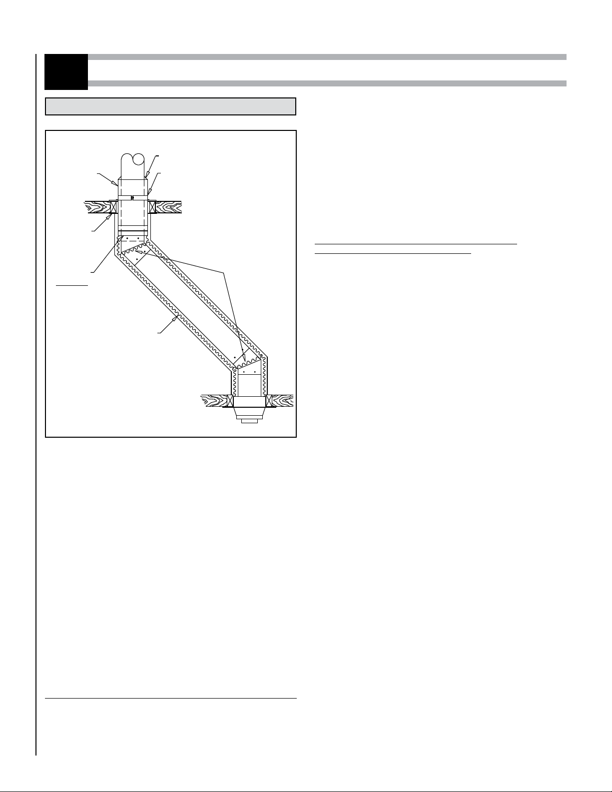
OFFSET DEVIATION
3
OFFSET CHIMNEY
If it is necessary to offset the chimney in order for it to pass through
an upstairs cupboard or to clear a joist, do this by using 15°, 30° or 45
insulated elbows. A maximum of two offsets (4 elbows in all) is allowed
in a chimney.
The minimum chimney height when using 15° offsets is 10’.
The minimum chimney height when using 30° offsets is 15’.
The maximum length of unsupported offset chimney is 6’. If the offset
chimney is longer than 6’, then it must be supported at 6’ intervals
using an offset support (DTC-RESU) or wall band (DTC-WSU). Or if a
Premium Shield is used then a Radiation Shield Connector (DTC-RSCI)
must be installed in the offset portion and attach to trusses with (2) two
plumbers straps.
INSTALLATION INSTRUCTIONS
If you are venting a Factory built fireplace or an oil or gas burning ap-
pliance please refer to installation notes #2 (on page 5) for guidelines
on the use of the Premium shields.
For Unenclosed installation or venting of oil or gas appliances:
Put the first chimney length in the support. Turn it clockwise to lock it
in place.
Note: the male coupling must be on top.
RADIANT
SHIELD
CONNECTOR
(DTC-RSCI)
RADIANT SHIELD
CONNECTOR SUPPORT
(DTC-RSSR)
FLEXIBLE
SHIELD
(DTC-FLXS)
SWIVEL
ADAPTORS
OPTIONAL
(DTC-SA)
SPRING
SPACERS
RADIANT
SHIELD
CONNECTOR
FIRESTOP
(DTC-FRSC)
Figure 11
Stack the next chimney length on the first length. Be sure that the male
and female threads are not in line when putting the lengths together. Turn
the chimney clockwise to lock it in place. You may add a 1/2in stainless
steel self tapping screw to prevent accidental unlocking. When you reach
the height at which the elbow will be installed:
Step 1. Install the insulated offset elbow on the vertical chimney length.
Turn it in the required direction and fasten it to the chimney with
the (4)-1/2" metal screws provided.
Step 2. Place the required offset chimney length (see chart below) on
the elbow. Turn it clockwise to lock it in place.
Step 3. Use another elbow to turn the chimney vertically. Again secure
the elbow to the chimney length using the (4)-1/2’’ metal screws.
For Enclosed installation (6", 7", and 8" dia. only)
(woodstove or coal burning appliance)
:
- Place the first chimney length on a flat surface with the male coupling
on top.
- Slide a flexible shield (DTC-FLXS) on top of that length all the way to
the bottom.
- Attach the flexible shield to the section using 3 x 1/2" stainless steel
self tapping screws.
- Slide this assembly in the support and turn clockwise to lock it in
place.
- At the ceiling level from the top, install a Radiation Shield Connector
(DTC-RSCI) and a Radiation Shield Support (DTC-FRSCS).
(see Figure 13).
Stack the next chimney length on the first length. Be sure that the male
and female threads are not in line when putting the lengths together. Turn
the chimney clockwise to lock it in place. You may add a 1/2 in stainless
steel self tapping screw to prevent accidental unlocking.
When you reach the height at which the elbow will be installed:
Step 1. Install the insulated offset elbow on the vertical chimney length.
Turn it in the required direction and fasten it to the chimney with
the (4)-1/2’ metal screws provided.
Step 2. Place the required offset chimney length (see table 8) on the
elbow. Turn it clockwise to lock it in place.
Step 3. Use another elbow to turn the chimney vertically. Again secure
the elbow to the chimney length using the (4)-1/2" metal screws.
Attach a spacer spring around the chimney at each elbow to help keep
the flexible shield centered. (See figure 11) Slide the flexible shield up
the chimney and attach it below the ceiling to the Support Radiation Shield
using 3 self tapping metal screws. If you are limited in space to screw,
install a Swivel Adaptor (DTC-SA) (figure 11) below the Shield Connector
(DTC-RSCI) and one on the top end of the flexible shield.
In the attic:
• If the chimney is not enclosed in the attic, a storm collar (DTC-SC) must
be installed on top of Radiation Shield to prevent any loose insulation
from falling in the area between the chimney and the support.
• If the chimney is enclosed in the attic, continue installing chimney
sections up through the roof opening. Lower a shield tube through
the roof opening and adjust it so it sits on top of the radiation shield
support. Adjust the length of the shield tube so that it terminates just
above the roof opening but under the flashing. Screw the sections of
the shields together.
FLASHING COLLAR (DTC-SC)

NOTE: DIAGRAMS & ILLUSTRATIONS ARE NOT TO SCALE. 9
OFFSET & RISE CHART MODEL DURATECH CANADA (DTC)
(5" @ 10")
Figure 12
WARNING
A support must always be installed right above each
offset (two elbows) to support the chimney above the
offset.
RISE
OFFSET
Install the remaining chimney as described in the instructions for the
Interior Straight installation.
INSTALLATION CALCULATIONS
Determine the offset required in view of the obstacles that must be avoided
(see figure 12). Refer to table 8 below to determine the elbows required
as well as the insulated length needed.
ANGLE DIA. INCHES ONE LENGTH BETWEEN ELBOWS TWO LENGTHS BETWEEN ELBOWS
8 12 18 24 36 48 8 & 48 12 & 48 18 & 48 24 &48 36 & 48 48 & 48
15° 5" @ 10" Offset 3-5/16 4-5/16 5-7/8 7-7/16 10-1/2 13-5/8 15-3/8 16-7/16 18 19-1/2 22-5/8 25-3/4
Rise 15-11/16 19-9/16 25-3/8 31-3/16 42-3/4 54-3/8 60-15/16 64-13/16 70-9/16 76-3/8 87 99-9/16
30° 5" @ 10" Offset 7-7/16 9-7/16 12-7/16 15-7/16 21-7/16 27-7/16 30-13/16 32-13/16 35-13/16 38-13/16 44-13/16 50-13/16
Rise 20 23-1/2 28-11/16 33-7/8 44-1/4 54-11/16 60-9/16 64 69-1/4 74-7/16 84-13/16 95-1/4
45° 5" @ 10" Offset 10-5/16 13-3/16 17-3/8 21-5/8 30-1/8 38-5/8 43-7/16 46-1/4 50-1/2 54-3/4 63-1/4 71-11/16
Rise 17-13/16 20-5/8 24-7/8 29-1/8 37-5/8 46-1/8 50-15/16 53-3/4 58 62-1/4 70-3/4 79-3/16
Table 8
OFFSET DEVIATION (CONT’D)
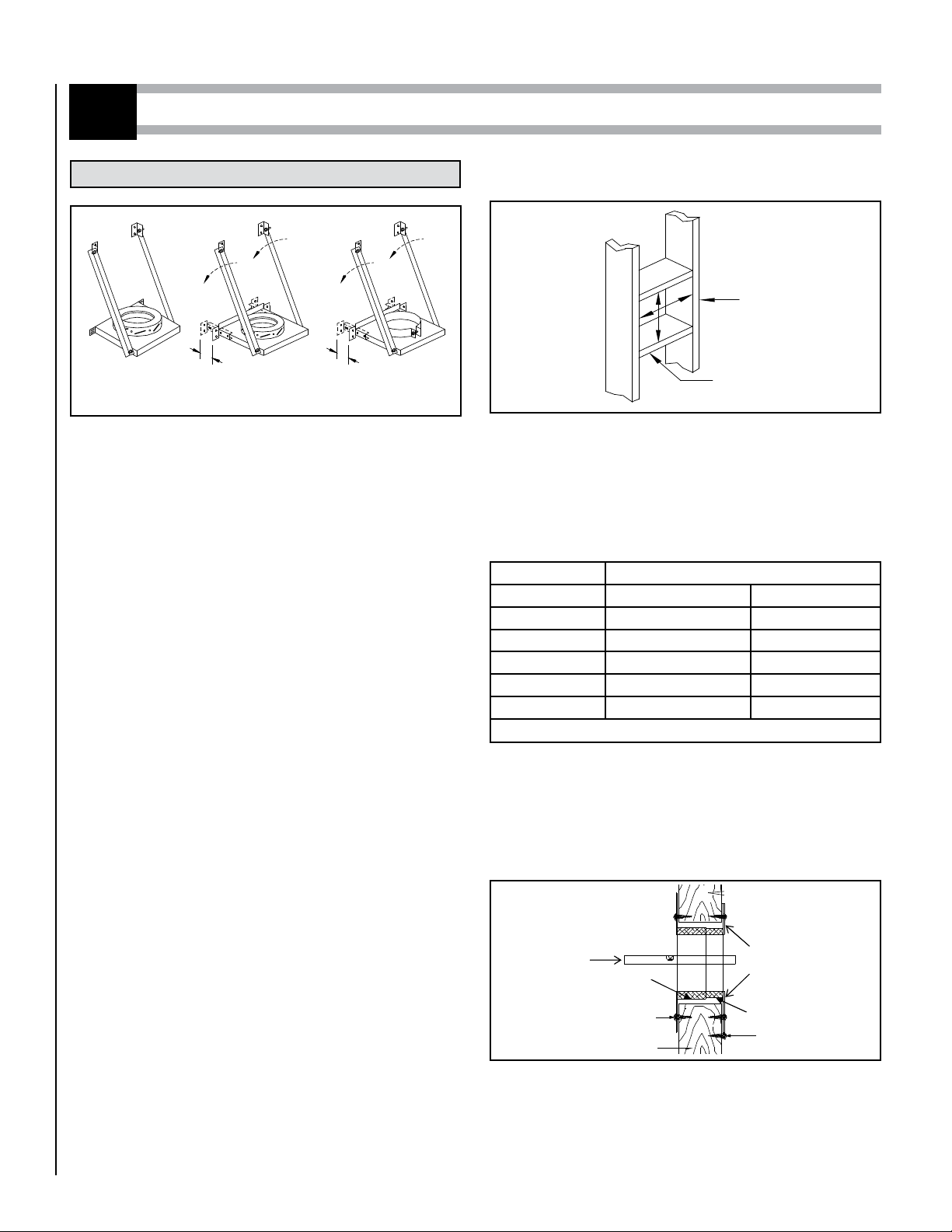
ROOF SUPPORT (DTC-RS)
The roof support has three possible uses:
It may be used to support a chimney from the roof. It adjusts to any
roof pitch.
It may be used on a floor, ceiling or roof above an offset to support the
chimney above the offset.
It may be used on a floor, ceiling or roof as a supplementary support when
the chimney height exceeds that of the primary support. (See maximum
length height supported, page 3).
INSTALLATION INSTRUCTIONS
With the chimney extending through the hole in the roof, ceiling or floor
and the radiation shield in place, proceed as follows (Refer to figure 15
for visual references):
Step 1. Assemble the support collar to fit your chimney diameter, as
described on the instruction sheet supplied with the support.
Step 2. Slip the support down over the stainless steel chimney until its
brackets rest on the roof or floor. Tighten the collar around the
chimney, then secure it by screwing the four 1/2" metal screws
(supplied) through the holes located on each side of the collar
bolts and into the chimney (Figure 32).
Step 3. Center the chimney and nail or screw the support to the roof or
floor using (8) - 2-1/2" nails or (8) N°8 - 1-1/4" wood screws.
(figure 14).
Figure 14
3
Figure 13
SCREWS
SCREWS
RADIATION SHIELD
CONNECTOR SUPPORT
(DTC-FRSCS)
RADIATION SHIELD
CONNECTOR
(DTC-RSCI)
SCREWS
Figure 15
RAIN CAP
(DTC-VC)
STORM COLLAR
(DTC-SC)
FLASHING
(DTC-FF)
ROOF SUPPORT
(DTC-RS
2 in. MIN
6 in. MIN
NOTE: DIAGRAMS & ILLUSTRATIONS ARE NOT TO SCALE.
10
DTC-TS DTC-TSAC
ADJUSTABLE ADJUSTABLE
DTC-TSA
EXTERIOR INSTALLATION
4
TEE & WALL SUPPORT
Three supports are available, an adjustable with collar (DTC-TSA), an
adjustable with coupling (DTC-TSAC) and a non-adjustable with coupling
(DTC-TS).
INSTALLATION NOTES
If possible, install an interior chimney as it will provide better performance
than an exterior chimney. In areas with continuous temperatures below
-18°C (0°F), the use of an exterior chimney may result in operating prob-
lems such as poor draft, excessive condensation of combustion products
and rapid accumulation of creosote when connected to a wood burning
appliance. If you do install an exterior chimney, we recommend that you
enclose it using an insulated enclosure.
1. The chimney may be enclosed or unenclosed. If enclosed at 2’’
clearance all around the chimney on a wood stove application, a
Premium shield must be installed around the chimney (Figure 19).
2. Maintain 2" clearance to combustible materials. Do not fill the 2" space
around the chimney with insulation or any other material.
3. A wall band must be used to secure the chimney to the wall. Maximum
distance between wall bands is 8 feet.
4. The minimum length of chimney extending past the inside wall is 5
inches.
5. The maximum length of chimney extending past the inside wall is 24
inches.
6. The distance between the stove pipe and a parallel combustible wall or
ceiling must not be less than 18". The distance between the horizontal
stove pipe and the unshielded vertical wall through which it passes
must not be less than 7 inches.
7. If an exterior installation is to be enclosed, allow for access to base
of tee to facilitate required cleaning.
8. The minimum distance between the bottom of the support and any
horizontal combustible (including the ground) is 6". This distance
can be reduced to 2 inches by using an insulated tee cap (DTC-TCI)
in conjunction with a (DTC-TSA) wall support.
9. The adjustable support (DTC-TSA) may only be installed with an
insulated tee cap (DTC-TCI) or a drain tee cap (DTC-TCD).
Figure 17
Figure 16
HOLE SIZE
CHIMNEY SIZE COMBUSTIBLE CONCRETE
5" 11-3/8’’ x 11-3/8’’ 7-3/4’’
6" 12-3/8’’ x 12-3/8’’ 8-3/4’’
7" 13-3/8’’ x 13-3/8’’ 9-3/4’’
8" 14-3/8’’ x 14-3/8’’ 10-3/4’’
10" 16-3/8’’ x 16-3/8’’ 12-3/4’’
Table 9
Wood walls: from outside, put the square wall thimble (DTC-WTI) in the
hole. Nail in place using (4) 2’’ nails or 1’’ screws. This wall thimble is
adjustable from 7’’ to 12’’. From inside, wrap the insulation pad around
the tube of the square wall thimble previously installed. Place the metal
sheet around the insulation pad and close it by joining the staples at each
end of the metal sheet together. Make sure the gap is completely filled in
from inside to outside (cut insulation pad to proper length).
WALL FRAMED OPENING
WALL STUDS
FRAME OPENING WITH LUMBER
THE SAME DIMENSION AS
WALL FRAMING
Determine where the chimney will pass through the wall.
• For concrete walls cut a hole slightly larger than the chimney.
• For combustible walls cut and frame a hole 4" larger than the chimney,
midway between the wall studs (see table below for sizing).
Normally wall studs are placed at 16" centers. With the hole midway
between them, the support will fasten to these studs and thus ensure a
strong attachment to the wall. (see Figure 17).
INSTALLATION INSTRUCTIONS STEPS
Slide the large wall shield over the small wall shield. Using a level make
sure that the hole for the chimney to pass through is horizontal. Screw
the inner thimble in place with the provided screws (see Figure 18).
Note: The cavity surrounding the wall thimble must be filled with type
R-20 insulation (see Figure 18).
Figure 18
INSIDE OUTSIDE
LEVEL TYPE R-20
INSULATION
SMALL WALL SHIELD
2" NAILS
WALL STUD
1" SCREWS
LARGE WALL SHIELD

NOTE: DIAGRAMS & ILLUSTRATIONS ARE NOT TO SCALE. 11
EXTERIOR INSTALLATION (CONT’D)
Attach the flue extension to the horizontal chimney length using the three
metal screws provided.
Stack a chimney length on top of the tee. Turn it clockwise to lock it in place.
FOR UNENCLOSED INSTALLATION OR VENTING OF OIL
OR GAS APPLIANCES:
Continue until the required chimney height is reached.
NOTE: At 8' intervals, attach the chimney to the wall using a wall band
(DTC-WSU).
If the chimney passes through the roof, cut a hole large enough to pro-
vide 2" clearance between the chimney and the roof. For pitch roof, see
table 3 on page 3.
FOR ENCLOSED INSTALLATION AT 2" FROM COMBUS-
TIBLES (Woodstove or coal burning appliance only):
Put a first chimney length on the Tee. Turn it clockwise to lock it in place
(see figure 4).
Note: the male coupling must be on top.
Slide a Radiation Shield Connector on that first chimney section and
fasten it using 3 self tapping metal screws.
Stack the next chimney length on the first length. Be sure that the male
and female threads are not in line when putting the lengths together. Turn
the chimney clockwise to lock it in place. You may add a 1/2in stainless
steel self tapping screw to prevent accidental unlocking.
Slide a telescopic rigid shield over that section and attach it to the radia-
tion shield connector.
Continue installing chimney sections up through the roof opening. Pull
the telescopic shield tube up to the roof opening Adjust the length of the
shield tube so that it terminates just above the roof opening but under
the flashing. Screw the sections of the shield together using 3 self tap-
ping screws per joint.
TO CONTINUE, SEE ROOF FLASHING INSTALLATION, ON PAGE 5.
Attach the clean-out cap to the support's flue extension using the
three metal screws provided. Make sure that the screws have pierced
through the flue extension. The cap is in the box with the insulated tee. If
an insulated tee cap is used, twist lock the tee cap to the tee (adjustable
support DTC-TSA only).
The minimum length of insulated chimney required to pass through the
wall will be thickness plus 7". The insulated chimney must extend at least
5" into the room beyond the finished wall. Insert this chimney length in
the side entry of the insulated tee. Turn it clockwise to lock it in place.
Seal this joint by wrapping it with the aluminium tape supplied with the
tee.Mount the insulated tee on the support so that the chimney length
which will go through the wall is perpendicular to the side of the support
that will fasten to the wall.
This step will require 2 people: (See figure 20)
Insert the chimney length of this tee-support assembly into the hole in
the wall. Using a level, ensure the tee is vertical, then attach the support
to the wall using (8) Nº. 10 x 1 - 1/4" wood screws or 4" spiral nails.
NOTE: To provide sufficient strength, the nails must be driven into the
wall studs. For concrete walls, the support should be attached using (8)
1/4" x 2" lag bolts.
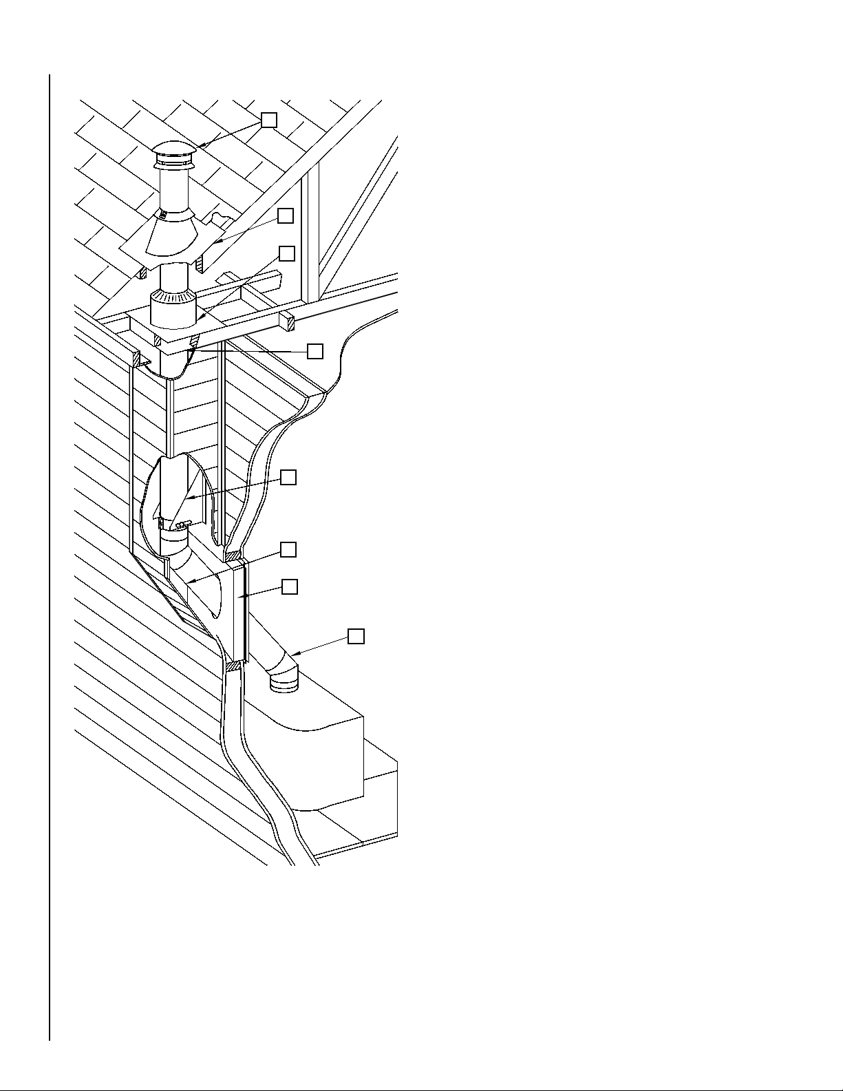
4
Figure 19
1. CAP
2. WALL THIMBLE
3. INSULATED TEE
4. INSULATED LENGTH
5. TEE SUPPORT
6. FLUE EXTENSION
7. PREMIUM SHIELD
8. RADIATION SHIELD FIRESTOP
9. RADIATION SHIELD CONNECTOR
10. STORM COLLAR
11. RAIN CAP
12. CENTERING SPRING
9
3
6
4
2
5
1
7
8
10
11
12
Figure 20
5" Min.
WALL THIMBLE
(DTC-WTI)
WALL STUD
FLUE EXTENSION
(DTC-AD)
4 in. Nails or #10 x 1-1/4 in. Screws
LEVEL
4 in. Nails or
#10 x 1-1/4 in. Screws
INSULATED
CHIMNEY
(DTC-_SS)
TEE SUPPORT OR ADJUSTABLE TEE SUPPORT
(DTC-TS OR DTC-TSAC) AND INSULATED TEE CAP
(DTC-TCSS) OR ADJUSTABLE WALL SUPPORT
(DTC-TSA) AND INSULATED TWIST-LOCK CAP
(DTC-TCI) OR DRAIN TEE CAP (DTC-TCD)

NOTE: DIAGRAMS & ILLUSTRATIONS ARE NOT TO SCALE.
12
DTC-ISI
DTC-FSI
INTERIOR INSTALLATION ON A FURNACE AND WATER HEATER
5
Figure 21
Figure 22
Figure 23 Figure 24
Step 1. Locate the chimney in a convenient place as near as possible to
the appliance outlet. Cut and frame the holes in the floor, ceiling
and roof where the chimney will pass.
NOTE: It is important to follow the cutting dimensions for the
floor openings prescribed in this manual. This way, the holes left
by the folded positioning tab of the firestop (DTC-FS or DTC-ISI)
will be blocked by the ceiling.
Chimney Size Hole size
5’’ 12-1/8’’ x 12-1/8’’
6’’ 12-1/8’’ x 12-1/8’’
7’’ 14-3/8’’ x 14-3/8’’
8’’ 14-3/8’’ x 14-3/8’’
10’’ 14-3/8’’ x 14-3/8’’
Table 10
Step 2. From below push the support into the framed hole. Nail the
support to the framed box using (12) 3" spiral nails (see Figure
21).
Step 3. Put this first chimney length in the support. Turn it clockwise to
lock it in place.
NOTE: The male coupling must be on top.
Step 4. From below, install a firestop (DTC-FS) in each floor through
which the chimney passes (see Figure 22).
Step 5. Stack the next chimney length on the first length. Be sure that
the male and female threads are not in line when putting the
lengths together. Turn the chimney clockwise to lock it in place.
Continue until the required chimney height is reached.
Step 6. At the attic level, install a firestop (DTC-FS), from below and an
attic radiation shield (DTC-ISI) from above (see Figure 23).
Step 7. U.S. ONLY: Install the roof radiation shields in the roof joists.
These shields consist of four metal plates. Nail one plate to each
side of the joist using (2) 2-1/2’’ nails.
Step 8. Put the roof flashing in place. Seal the joint between the roof
and the flashing with roofing pitch.
For sloping roofs, place the flashing under the upper shingles
and on top of the lower shingles.
Nail the flashing to the roof using roofing nails.
Step 9. Place the storm collar over the chimney and the flashing. Tighten
it with the bolt supplied making sure the joint is properly caulked
(see Figure 24).
Fit the rain cap to the top of the chimney. Turn it clockwise to
lock it in place.
FINISH SUPPORT
(DTC-FSC) or (DTC-BS) NAILS
9
8
7
4
64
5
4
3
1
2
1. C0NNECTOR
2. BASE TEE FOR
TWIN CONNECTIONS
3. FINISH SUPPORT
4. FIRESTOP
5. INSULATED LENGTH
6. ROOF SUPPORT
7. ATTIC RADIATION
SHIELD
8. FLAT ROOF FLASHING
9. REGULAR RAIN CAP
SILICONE
CAULKING
NOTE: DIAGRAMS & ILLUSTRATIONS ARE NOT TO SCALE. 13
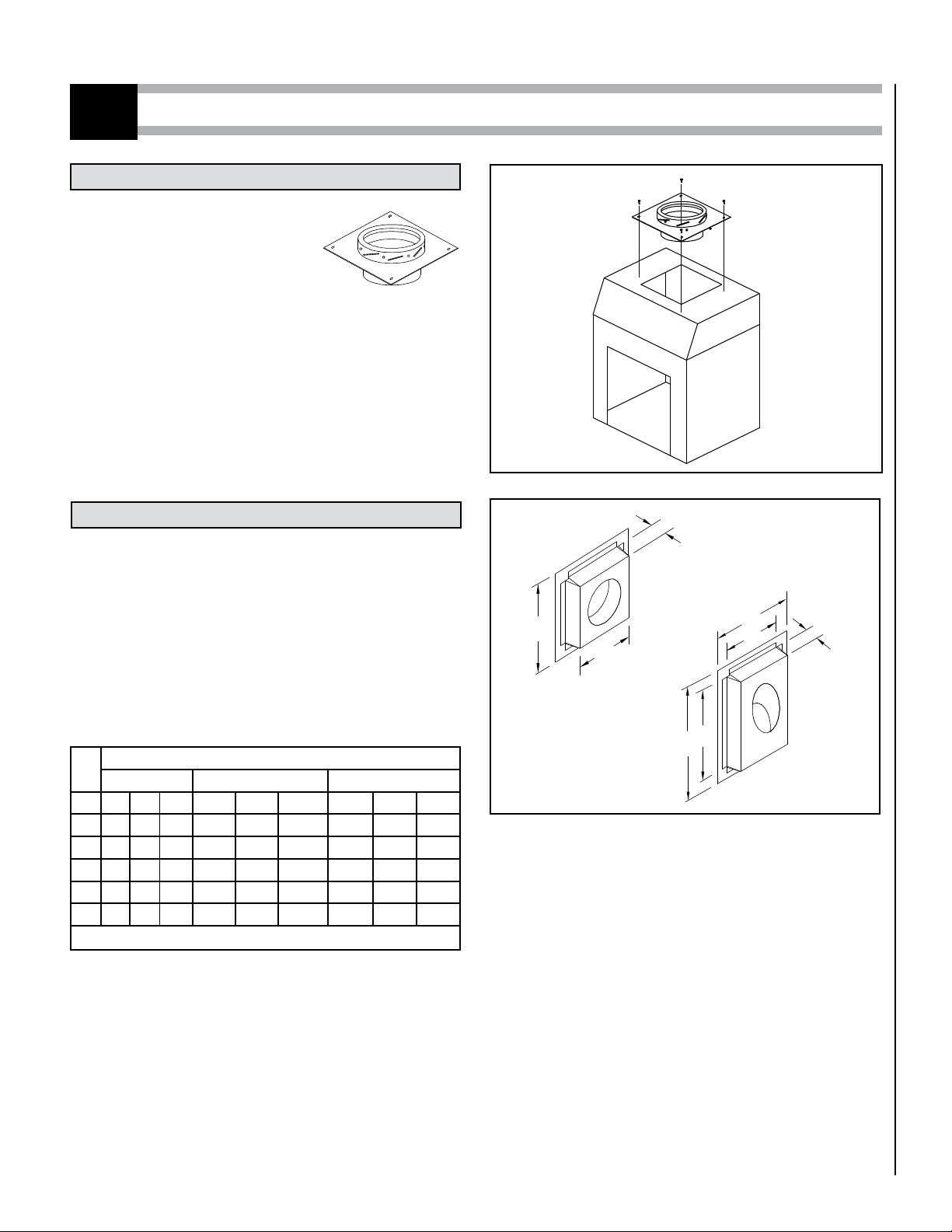
SPECIALIZED COMPONENTS
ANCHOR PLATE (DTC-AP)
INSULATED WALL RADIATION SHIELDS
This support is used on a masonry fireplace
or on top of a furnace to provide a positive
connection to the chimney. It is not to be
used in contact with any combustible mate-
rial, such as on a wood floor.
INSTALLATION INSTRUCTIONS
Once the appliance is installed, bolt the anchor plate to it. Install the
chimney according to the installation instructions for the finish support
(DTC-FSC).
FACTORY-BUILT FIREPLACES
For chimneys installed on factory-built fireplaces, follow the installation
instructions accompanying the fireplace.
INSULATED RADIATION SHIELD (DTC-FSI)
It must be used in combination with an attic radiation shield (DTC-ISI)
when passing through an attic. This component provides a 2"-safety
clearance to combustible materials surrounding the chimney.
ANGLED INSULATED RADIATION SHIELD
(DTC-WRSI30/DTC-WRSI45)
It has been designed for use when a chimney passes through a wall at
an angle. (See figure 27 for application).
Ø
INT.
FRAMING SIZE
DTC-FSI DTC-WRSI30
DTC-WRSI45
7’’ 8’’ 10’’ 7’’ 8’’ 10’’ 7’’ 8’’ 10’’
A 16 16 18 37-3/4 39-3/4 45-5/16 26-5/8 28 30-1/2
B 3 3 3 16-5/8 17-5/8 19-3/8 16-5/8 17-5/8 19-3/8
C 13 13 5 12-5/8 13-5/8 15-3/8 12-1/8 13-1/2 14-7/8
D -- -- -- 33-3/4 35-3/4 39-1/4 22-1/8 23-1/2 26
E -- -- -- 3 3 3 3 3 3
Table 11
DTC-AP
Figure 25
Figure 26
A
B
CDTC-FSI
DTC-WRSI30
DTC-WRSI45
AD
B
CE
NOTE: DIAGRAMS & ILLUSTRATIONS ARE NOT TO SCALE.
14
Figure 27
1. INSULATED ELBOW
2. INSULATED WALL RADIATION SHIELD
3. INSULATED LENGTH
4. OFFSEST SUPPORT
5. FIRESTOP
6. ATTIC RADIATION SHIELD
7. ADJUSTABLE ROOF SUPPORT
8. RAIN CAP
8
7
6
5
4
3
2
1

15
M&G DuraVent Limited Lifetime Warranty
M&G DuraVent, Inc. (“DuraVent”) provides this limited
lifetime warranty for all of its products with the exception
of Ventinox® (lifetime), and PolyPro® (ten years). Subject
to the limitations set forth below, DuraVent warrants
that its products will be free from defects in material or
manufacturing, if properly installed, maintained and used.
DuraVent products are fully warranted if installed only by a
professional installer. This Warranty is transferable from the
original homeowner to the buyer of the home. This warranty
does not cover normal wear and tear, smoke damage or
damage caused by chimney res, acts of God, or any product
that was: (1) purchased other than from an authorized
DuraVent dealer, retailer or distributor; (2) modied or
altered; (3) improperly serviced, inspected or cleaned; or
(4) subject to negligence or any use not in accordance with
the installation instructions included with the product
as determined by DuraVent. Installation instructions are
available online at www.duravent.com under Support/
Literature and through our Customer Service Department
800-835-4429 or customerser[email protected]om. This
limited lifetime warranty applies only to parts manufactured
by DuraVent.
DuraVent provides the following warranties for its products:
One Hundred Percent (100%) MSRP 15 years from the date of
purchase, and Fifty Percent (50%) thereafter, except for the
following limitations on: all Termination Caps and DuraBlack®
are warranted at One Hundred Percent (100%) for ve years.
All warranty obligations of DuraVent shall be limited to repair
or replacement of the defective product pursuant to the
terms and conditions applicable to each product line. These
remedies shall constitute DuraVent’s sole obligation and sole
remedy under this warranty. This warranty provides no cash
surrender value. The terms and conditions of this warranty
may not be modied, altered or waived by any action,
inaction or representation, whether oral or in writing, except
upon the express, written authority of an executive ocer of
DuraVent.
Corn, bio-fuels, driftwood or other wood containing salt,
preservative-treated lumber, plastic and household trash or
garbage, or wood pellets containing such materials must not
be burned in the appliance or replace. In case of a chimney
re, the chimney must be inspected and approved by a
certied Chimney Sweep before reuse. After each annual
inspection, maintenance, and cleaning, the certied Chimney
Sweep must ll out and date the appropriate section of the
warranty card provided with the chimney liner.
LIMITATIONS ON INTERNET SALES: Notwithstanding any
other terms or conditions of this Limited Lifetime Warranty,
DuraVent provides no warranty for the following specic
products if such products are not installed by a qualied
professional installer: DuraTech®, DuraTech® DTC, DuraPlus
HTC®, DuraChimney® II, PelletVent Pro®, DirectVent Pro®,
FasNSeal®, FasNSeal® W2, FasNSeal® Flex, and PolyPro®, and
Member of M&G Group 800-835-4429 www.duravent.com L209 3/2012
®
M&G DuraVent’s relining products including DuraLiner®,
DuraFlex® (SW, Pro, 316, 304), and Ventinox®. For purposes
of this warranty, a trained professional installer is dened as
one of the following: licensed contractors with prior chimney
installation experience, CSIA Certied Chimney Sweeps, NFI
Certied Specialists, or WETT Certied Professionals.
DuraVent must be notied and given the opportunity to
inspect defective product prior to replacement under the
terms of this limited lifetime warranty. All warranty claims
must be submitted with proof of purchase. Labor and
installation costs are not covered under this warranty. To
obtain warranty service contact: DuraVent Warranty Service,
877 Cotting Ct., Vacaville CA 95688, or call 800-835-4429.
WHERE LAWFUL, DURAVENT DISCLAIMS ALL OTHER
WARRANTIES, INCLUDING BUT NOT LIMITED TO IMPLIED
WARRANTIES OF MERCHANTABILITY AND FITNESS FOR A
PARTICULAR PURPOSE. IN NO EVENT WILL DURAVENT BE
LIABLE FOR INCIDENTAL, CONSEQUENTIAL, PUNITIVE OR
SPECIAL DAMAGES OR DIRECT OR INDIRECT LOSS OF ANY
KIND, INCLUDING BUT NOT LIMITED TO PROPERTY DAMAGE
AND PERSONAL INJURY. DURAVENT’S ENTIRE LIABILITY
IS LIMITED TO THE PURCHASE PRICE OF THIS PRODUCT.
SOME STATES DO NOT ALLOW LIMITATIONS ON IMPLIED
WARRANTIES, OR THE EXCLUSION OR LIMITATION OF
INCIDENTAL OR CONSEQUENTIAL DAMAGES, SO THE ABOVE
LIMITATIONS AND EXCLUSIONS MAY NOT APPLY TO YOU.
THIS LIMITED WARRANTY GIVES YOU SPECIFIC LEGAL RIGHTS,
AND YOU MAY ALSO HAVE OTHER RIGHTS THAT VARY FROM
STATE TO STATE.
For the most up-to-date installation instructions, see
www. duravent.com
REV 2.27.2013
Manufactured in Vacaville CA and Albany NY

16 Printed in Canada © 2013 DURAVENT
WARRANTY
This product has a limited lifetime warranty. Please read the warranty to
be familiar with its coverage.
Retain this manual. File it with your other documents for future refer-
ence.
PRODUCT REFERENCE INFORMATION
Please contact Duravent for the phone number of your nearest Duravent
dealer who will answer your questions or address your concerns.
Normally, all parts should be ordered through your Duravent distributor
or dealer. Parts will be shipped at prevailing prices at time of order.
When ordering repair parts, always give the following information:
1. The model number of the vent system.
2. The part number.
3. The description of the part.
4. The quantity required.
5. The installation date of the chimney system.
If you encounter any problems or have any questions concerning the
installation or application of this system, please contact your dealer.
DURAVENT
Visit us at www.duravent.com
Duravent reserves the right to make changes at any time, without notice, in design, materials,
specifications, prices. Consult your local distributor for chimney system code information.
Duravent
www.duravent.com
Table of contents
Other M&G Fan manuals


