M&H 4500 User manual

M&H VALVE COMPANY
AWWA C504-00
BUTTERFLY VALVES
CLASS 150 & 250
SIZES 3” THRU 72”

Page 2 of 27
TABLE OF CONTENTS
Section Title Page
1 Butterfly Valves for Water Works Applications 4
1.1 Introduction 4
1.2 AWWA Specification 4
1.3 Applications 4
1.4 Seat Design 5
1.5 Shaft & Vane Design 5
1.6 Actuation 5
1.7 Automation 6
1.8 Coating 6
1.7F Automated Valve Information Form 7
2 Installation & Testing 8
2.1 General 8
2.2 Unloading & Storage 8
2.3 Installation Safety 9
2.4 Inside Diameter of Mating Pipe 9
2.4D Mating Pipe Inside Diameter Drawing 10
2.5 Pipe Connection 11
2.5.1 Mechanical Joint Follower Glands 11
2.5.2 Flanged End Connections 11
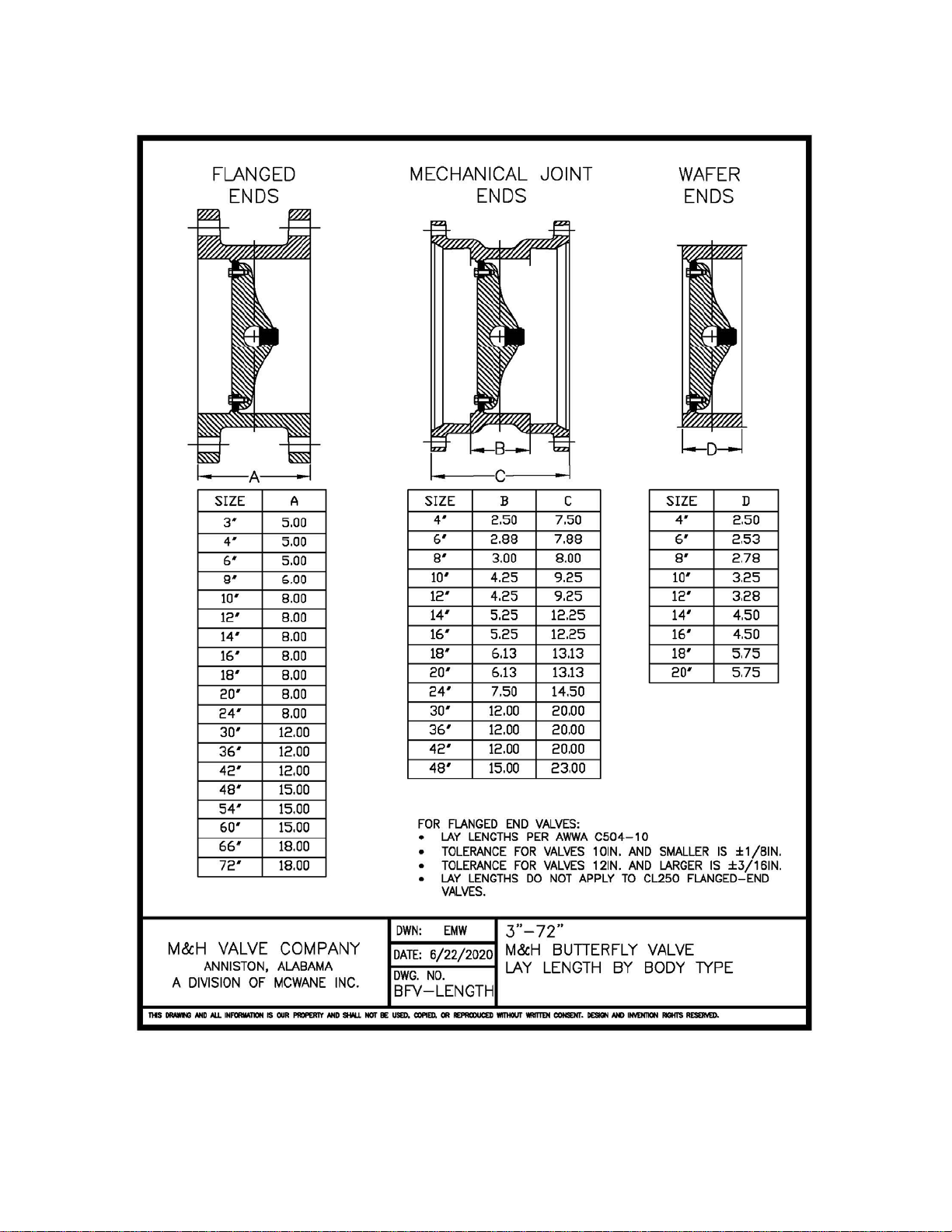
2.5D Valve Body Lay Length Dimensions 12
2.6 Assembly 13
3 Pressure Testing of M&H BFVs 15
3.1 General 15
3.2 Mechanical Issues 15
3.3 Compressed Air 15
3.4 Hydrostatic Test 16
3.5 Service Support 16
4 Operation of M&H BFVs with Traveling Nut Operators 17
4.1 General 17
4.2 Input Torque 17
4.3 Throttling 17
4.4 Water Hammer 17
4.5 Turns to Open 18

Page 3 of 27
5 Maintenance 19
5.1 Safety 19
5.2 Vane Seat Ring Adjustment – Sizes 3” thru 72” 19
5.3 Vane Seat Ring Replacement 20
5.3.1.1 3” thru 24” Removal of Existing Vane Seat Ring 20
5.3.1.2 3” thru 24” Installation of New Vane Seat Ring 20
5.3.1.3 Service Details 20
5.3.2.1 30” thru 72” Removal of Existing Vane Seat Ring 21
5.3.2.2 30” thru 72” Installation of New Vane Seat Ring 22
5.3.2.3 Service Details 22
5.4 M&H BFV Traveling Nut Operator 23
5.4.1 General 23
5.4.2 External Obstruction 23
5.4.3 Internal to the Operator Obstruction 24
5.4.4 Internal to the Valve Obstruction 24
5.5 Vane Level Adjustment 25
5.5.1 Vane Level Adjustment Procedure for 3” thru 12” BFVs 25
5.5.2 Vane Level Adjustment Procedure for 14” thru 42” BFVs 25
5.5.3 Vane Level Adjustment Procedure for 48” thru 72” BFVs 26
5.6 Protective Coatings 27

Page 4 of 27
SECTION 1
BUTTERFLY VALVES FOR WATER WORKS APPLICATIONS
SECTION 1.1 – INTRODUCTION
The M&H butterfly valve (BFV) was introduced in 1965 for clean water applications. The rubber seat
provides a ‘zero leakage’ alternative to the metal-seated valves used at that time. BFVs offer flow control
advantages and economy vs. gate valves, which become increasingly more significant with larger sizes.
BFVs are commonly used in water transmission and distribution for sizes 12” and larger. For pump
station and treatment plant applications, BFVs offer flow control advantages (such as throttling) over gate
valves.
M&H butterfly valves are manufactured in accordance with the current version of the American Water
Works Association (AWWA) C504 standard. They are constructed of ductile iron, stainless steel, rubber
seats & seals, and Teflon trim. Corrosion resistance and strength of ductile iron makes this a very suitable
material for buried service. Stainless steel components provide corrosion resistance as required for water
service applications.
SECTION 1.2 – AWWA SPECIFICATION
Butterfly valves are addressed in the American Water Works Association (AWWA) standard
C504(current edition). Sizes covered are 3” thru 72” with end configurations being mechanical joint (MJ)
or 125# ANSI flanged (FLG) for all sizes and wafer style valves in 3” thru 20”. Mechanical joint x
flanged ends are generally produced up to the 16” size.
Rubber seated butterfly valves are designed to provide a 100% shut off at operating pressures in
accordance with AWWA C504. The current C504 standard covers pressure ratings from 25 to 250 psi
with velocities from 8 to 16 fps. The most used rating is Class 150B which is a 150psi pressure rating at
16fps flow rate.
C504 also allows for Class 250B BFVs which have a pressure rating of 250psi at 16fps flow rate. Due to
the increased pressure rating, CL250B BFVs require more torque to open and close the valve. The
increased torque requirement may require larger operators for the operating conditions. CL250 BFVs can
have ANSI Class 125 flanges to accommodate most water systems but can also have ANSI Class 250
flanges with either a CL125 hole pattern or a CL250 hole pattern. These options must be specified at the
time of order.
Valve body material and related wall thickness are specified in AWWA C504, Table 1. The wall
thickness required for CL250B and CL150B valves is the same, when the CL250B body material is
ductile iron.
SECTION 1.3 – APPLICATIONS
M&H BFVs are designed primarily for potable water service and clean water applications. Because a
BFV is a quarter-turn valve with the vane always in the waterway, BFVs are not recommended for
wastewater or applications where debris or sediment may collect around the vane. Air service is
acceptable for BFVs up to 25 psi assuming that the air does not contain abrasive ash or other corrosive

Page 5 of 27
elements. EPDM rubber is used for the main seals of the BFV and has nominal temperature rating of 225
degrees F. The EPDM seals should not be used in any situation where contact with even trace amounts of
petroleum-based products may occur. Throttling operations that generate velocities up to 16 feet per
second (fps) are acceptable as covered in the C504 standard for class B. However, a BFV is not
considered a pressure-regulating valve and is not designed for prolonged operation at less than 20 degrees
open.
SECTION 1.4 – SEAT DESIGN
When selecting Butterfly Valves, the potential service life of the rubber seat and its serviceability should
be considered. To provide for in line seat maintenance, provisions for safe access can be incorporated into
the design of larger piping systems.
AWWA C504 states "Rubber seats shall be applied to the body or the vane". For valves 30" and larger,
C504 requires the design “to permit removal and replacement without the removal of the valve from the
installation site”. A mechanically retained rubber seat, which is offset from the shaft, is commonly used
due to its reliability and field serviceability.
The Valve Seat servicing is further referenced in the Appendix of C504 noting, “in some instances, valve
design permits field adjustment or replacement of rubber seats”. Configurations like this have
mechanically retained seats and seat accessibility without disassembly of the shaft/vane assembly.
SECTION 1.5 – SHAFT & VANE DESIGN
AWWA C504 covers the use of either a single piece shaft or a two-piece “stub” shaft. A single piece shaft
is common for the 3” thru 12” sizes. For 14” & larger sizes, a stub shaft is common. Stub shafts allow
enhanced flow characteristics by use of a recessed vane back design and/or open vane structure. For
corrosion resistance in potable water applications, valve shafts are generally type 304 stainless steel for
CL150B valve or high strength 630 stainless steel for CL250B valves.
An offset shaft design can reduce seat wear since the vane does not make full contact with the seating
surface in the body until closing. This is of greatest concern with the continual positioning associated with
automated operation.
SECTION 1.6 – ACTUATION
An operator is used to open and close the BFV. Operators can be mechanical gear operators,
pneumatic/hydraulic cylinder operators or electric motors. The most common mechanical operator is a
traveling nut operator. One of the main advantages of the traveling nut operator is that assuming the
operator input shaft is turned at a constant speed, the vane will slow as it reaches the closed position thus
minimizing any water hammer effects. This operator will hold its place in any intermediate position and
prohibit flow from moving the vane.
BFVs can be supplied with third-party manufactured worm gear operators as required by the purchaser or
contract. Worm gear operators designed to the AWWA C504 standard must be capable of accepting 300
ft-lb of input torque on wrench nuts.

Page 6 of 27
IMPORTANT – Do not remove a BFV operator while under flow and pressure. Without
an operator in place holding the vane, a BFV will try to close in the presence of flow and
can create a hazardous water hammer situation. Also, the operator may serve to retain
shaft seals, which could be ejected without the operator mounted on the valve.
Valves equipped with manual operators for open, close, or throttling service generally do not require
preventative maintenance. Operator settings are adjusted during the assembly process and tested at full
closure; thus an operator adjustment is rarely required. Consult the specific manufacturer to obtain
detailed information regarding the maintenance of each type of operator provided.
SECTION 1.7 – AUTOMATION
Selection of a valve type for automation includes numerous application specific considerations. From a
cost standpoint, a quarter turn BFV is generally more economical to automate than a multi turn gate valve.
Manufacturers can provide automation to suit virtually all control even those with very specific design
criteria. When specifying, pricing, or ordering automated valves, the information required includes
pressure & velocity, open/close or modulating service, available power supply, control requirements, and
type of protective enclosure. A data sheet that more fully covers application conditions is available on the
following page.
For automation of existing manual operator installations, it is suggested to contact an area operator
representative to determine and provide for those specific needs.
Variable degrees of preventative maintenance will be required based on the type of equipment and its
application. Consult the manufacturer of the operator for service information including required
preventative maintenance and detailed service procedures.
SECTION 1.8 – COATINGS
M&H standard coating for BFVs is fusion bonded epoxy meeting the requirements of AWWA C550,
Protective Epoxy Interior Coatings for Valves and Hydrants and NSF61, Drinking Water System
Components. In certain cases, two-part sprayed-on epoxy may be used meeting the same requirements.
OPEN LEFT Operating Nuts and Handwheels are coated with black fusion bonded epoxy.
OPEN RIGHT Operating Nuts and Handwheels are coated with red fusion bonded epoxy.

Page 7 of 27
AUTOMATED VALVE INFORMATION FORM
Date:
To:
Project:
Engineer:
Bid Date:
Quantity
Size
Valve type
Pressure Class
Max Operating PSI
Service
Current (Voltage/Phase)
Open / Close Time
Open Close Service
Throttling
Modulating
Maximum Temp
Type Motor, Weather/explosion proof. Etc
Type of Reversing Controller, Nema Class
Type of Pushbutton Station, Nema Class
Pushbutton Station
Control Voltage
Special Requirements
Suggested Operator
Estimating Cost
Price Quote
Delivery
Prior to order, complete specifications and operating conditions will be required. M&H will
warranty valves with automation installed as per AWWA C504, Section 5.21 and 5.22.

Page 8 of 27
SECTION 2
INSTALLATION OF M&H MODEL 4500 &1450 BFVS
SECTION 2.1 – GENERAL
Butterfly valves are an important part of any water distribution system or treatment plant operation. Valve
failure due to faulty installation, improper operation, or maintenance in such systems could result in
damage, down time, and costly repairs. In buried or underground installations, problems or malfunctions
can result in extensive and costly unearthing operations to correct or eliminate the problem. Many
problems with butterfly valves can be traced to improper installation, operation, or maintenance
procedures.
Make sure flange faces, joint sealing surfaces, body seats, and vane are clean. Check bolting attaching
operator for loosening in transit and handling. If loose, tighten firmly. Open and close valve to make sure
it operates properly and that the stops or limit switches are set correctly so the valve fully closes and seats.
Close the valve before installing. For dry operation prior to installation, it is suggested that an NSF61
approved lubricant be applied to the rubber seat before moving the vane.
Handle valves carefully when positioning, avoiding contact or impact with other equipment, vault walls,
or trench walls.
M&H BFVs are rated for the designated operating pressure with flow in either direction. The
mechanically retained seat on the vane provides for adjustment or replacement with relative ease. It is
recommended that BFVs be installed with the seat side positioned for best access to the seat for future
maintenance.
Foreign material in a butterfly valve can damage the rubber seat when valves are operated. Be sure
interiors and adjacent piping is cleaned of foreign material prior to assembling the pipe joint connection.
SECTION 2.2 – UNLOADING & STORAGE
Inspect valves on receipt for damage in shipment and conformance with quantity and description of the
shipping notice and order. Unload all valves carefully to the ground without dropping. For valves 36
inches and larger, use forklifts or slings under skids. For smaller valves, do not lift valves with slings or
chains around the operating shaft, operator, or through waterway. Lift these valves with eyebolts or rods
through the flange holes.
After securing the valve with the chosen lifting method, always assume the valve can fall despite your
best effort to secure the valve. It is critically important to never be too close to, or under, the valve being
lifted due to the potential for failure of the lifting mechanism being used.
Protect the valve and operators from weather and the accumulation of dirt, rocks, and debris. When valves
fitted with power operators and controls are stored, energize electric operators or otherwise protect
electrical control equipment to prevent corrosion of electrical contacts due to condensation resulting from
temperature variation.

Page 9 of 27
SECTION 2.3 – INSTALLATION SAFETY
Before any installation of BFVs begins, make sure that all related safety procedures and protocols are
followed.
For Buried Service BFVs, any work to be done in an open trench should be in accordance with
OSHA regulation CFR 1926, Subpart P “Excavations”.
For Vault Service BFVs, all entry should be in accordance with OSHA regulation CFR 1910.146
“Confined Spaces”.
For In-Plant BFVs, installation and design should be in accordance with ASME Pressure Vessel
Code and other applicable standards.
Individual states may have more stringent regulations. Contact the appropriate state agency before any
work is begun for additional information and any potential permitting requirements.
SECTION 2.4 – INSIDE DIAMETER OF MATING PIPE
The Inside Diameter (ID) of the mating of the piping system should be considered BEFORE installing the
valve. When BFVs open, the vane will extend into the mating piping system. With many thick wall
plastic piping systems, there is the potential for the BFV vane to interfer with the pipe wall during
opening. This situation applies to all AWWA BFVs, barring a substantially undersized vane. For the
Mating Pipe wall clearance for M&H BFVs, see Drawing BFV-VANE:

Page 10 of 27

Page 11 of 27
SECTION 2.5 – PIPE CONNECTIONS
For connecting pipe to the BFV, do not deflect the pipe to connect the valve. Do not use as a jack to pull
into alignment. As much as reasonably possible, the BFV should be in an “unconstrained” position with
the weight of the valve being supported independently of the pipe connection. Pipe connections can put
undo stress on the valve pulling the valve body out of shape and causing it not to seal properly. This
becomes increasingly important as the piping size get larger.
Section 2.5.1 – Mechanical Joints
For Mechanical Joints (MJs) bolting torques should not exceed the recommended torque limits in the
appendix of AWWA C-111.
a. The use of an NSF61 approved pipe grade lubricant is recommended to minimize gasket to
pipe binding.
b. The most important factor is pulling the gland down uniformly so that the face of the gland
follower remains parallel to the face of the valve flange throughout the tightening cycle. The
torque on the nuts should be uniform, utilizing an alternating star pattern with as many as five
repetitions of tightening to assure even torque stress.
c. The MJ bolts should be torqued in accordance with the AWWA C111 specification. See the
chart below for a quick reference. Torques in excess of the recommendations below may
damage the BFV, the Mechanical Joint gland or both.
Valve Size Bolt Size Range of Torque
in. mm lbf-ft N-m
3” 5/8 15.9 45-60 61-81
4” – 24” 3/4 19.1 75-90 102-122
30” – 36” 1 25.4 100-120 136-163
42” – 60” 1 ¼ 31.8 120-150 163-203
*AWWA C111-17, Table A.1, Mechanical-joint torque loads
Section 2.5.2 – Flanged Ends
Standard flanged ends for M&H BFVs are Class 125B flanges as per ANSI B16.1.
For 100-degree water, ANSI Class 125B flanges for 12” and smaller valves are rated for 300 psi and 14”
thru 48” flanges are rated for 230 psi. For cold water service, M&H recommends a maximum of 250 psi
for 14” and larger Class 125B flanges. ANSI Class 250B flanges are an available option for M&H BFVs,
having hydrostatic shell test pressure rating of 450 psi for cold water service.
The lay length of M&H BFVs is in accordance with AWWA C504, see drawing BFV-LENGTH.
Page 12 of 27

Page 13 of 27
All bolting patterns are in accordance with ANSI B16.1. Bolt torques for flanged valves should be based
on the yield strength of the bolt. Due size and casting restrictions, BFV sizes 14” and larger have some
number of tapped holes (instead of thru holes) in the flanges. These are located around the Operator or
Thrust Ends. Studs or threaded rods are used at locations where there is not enough room for
standard bolts & nuts.
The chart below shows Thread Depth (or flange thickness), Thread Size and number of threaded
holes per flange for sizes 14” and above. To determine the total required length of the stud, add
this dimension to the thickness of the adjoining flange plus the thickness of the appropriate nut.
Valve
Size Thread Depth /
Flange Thickness Thread Size # OF THREADED
HOLES PER
FLANGE
14" 1 3/8" 1"-8 UNC 4
16" 1 7/16" 1"-8 UNC 4
18" 1 9/16" 1 1/8"-7 UNC 4
20" 1 11/16" 1 1/8"-7 UNC 4
24" 1 7/8" 1 1/4"-7 UNC 4
30" 2 1/8" 1 1/4"-7 UNC 4 (DOM); 8 (IMP)
36" 2 3/8" 1 1/2"-6 UNC 4 (DOM); 6 (IMP)
42" 2 5/8" 1 1/2"-6 UNC 4
48" 2 3/4" 1 1/2"-6 UNC 8
54" 3" 1 3/4"-5 UNC 12
60" 3 1/8" 1 3/4"-5 UNC 12
66" 3 3/8" 1 3/4"-5 UNC 12
72" 3 1/2" 1 3/4"-5 UNC 12
DOM – Domestic Valve, IMP – Imported Valve
If it is determined to use a bolt rather than a stud, add the tapped bore dimension plus the
adjoining flange dimension to acquire the required bolt length. (Bolt length as measured from the
base of the bearing surface - or head - to the end of threads). Also, check the adjoining fitting and
flange clearances to confirm there exist enough room to swing the bolt into place.
SECTION 2.6 – ASSEMBLY
The weight of the valve should be supported independent of the pipe connection. Provisions for thrust
restraint must be adequate to absorb closing thrust.
Prior to assembly, flange faces must be cleaned to remove rust, paint runs, or other impediments to
smooth surfaces. This will aid in gasket sealing without applying excessive bolt up torques.

Page 14 of 27
Butterfly valves having an AWWA C550 epoxy coating must be checked for an uneven finish or runs. If
allowed by the project specifications - use a mild abrasive to smooth the flange end surface.
Rubber gaskets must be suitable for cold water service and compatible with any other special
requirements of the application.
Butterfly valves should not be installed at a dead end or near a bend in a pipeline without proper &
adequate restraint to support the valve and prevent it from blowing off the end of the line. It is good
engineering practice to consider whether or not thrust blocks, restrained joints, or other means of restraint
are needed on or adjacent to valves on pipelines and/or where unusual conditions exist, such as high
internal pressures, adjacent fittings, or unsuitable soils.
Buried valves installed with valve boxes shall be installed so that the valve box does not transmit shock or
stress to the valve operator as a result of shifting soil or traffic load.

Page 15 of 27
SECTION 3
PRESSURE TESTING OF M&H BUTTERFLY VALVES
SECTION 3.1 – GENERAL
Testing of newly installed waterlines is a time-consuming process that can be complicated by failure to
retain specified pressures. This information is intended to aid in both the prevention of - and determining
the source of - a waterline testing problem.
This summary is based on field conditions common to new pipeline installation with specific emphasis on
valve installations. References are made to American Water Works Association (AWWA) C600
“Installation of Ductile Iron Water Mains and their Appurtenances”, AWWA C504 “Rubber Seated
Butterfly Valves” Appendix “A”, “Installation, Operation, and Maintenance of Rubber Seated Butterfly
Valves”.
While manufacturing issues are rarely the cause of testing failures. Most testing problems are related to
testing procedures, construction procedures, or an improper application.
Before field servicing of valves is performed, contact the area M&H Valve distributor or representative
for complete service information. Note that a BFV operator should never be removed with the waterline
under flow or pressure.
SECTION 3.2 – MECHANICAL ISSUES
Hydrostatic testing of waterlines is addressed in AWWA C600. Section 4.3.9, “Flushing”, recognizes that
“Foreign material left in pipeline during installation often results in valve or hydrant leakage during
pressure testing”. This remains a common cause of testing failure relating to valves & hydrants. Thorough
flushing of the waterline is recommended prior to pressure testing and help to remove any foreign matter
inadvertently left in the line.
Performing an inspection of the valve prior to installation as recommend in the Appendix of AWWA
C504 and can also avert testing problems. This includes checking for shipping damage, verifying bolt
tightness, and operating the valve through one complete open - closing cycle.
In normal service, seat lubrication is achieved by water in the line. Thus, before testing, operating the
valve to achieve full wetting of seating surfaces will facilitate better testing results. An NSF61 approved
lubricant should be used provide lubrication for dry testing before installation.
Test pump equipment and its connection to the pipeline needs to be fully checked for leakage. All fittings
must be wiped dry to aid in detection of leaking connections.
According to AWWA C504, gear operated BFV’s are to provide for closure with a maximum rim pull of
80 lb on the handwheel or chainwheel and a maximum input of 150 ft-lbs on wrench nuts. The range of
vane travel can normally be adjusted by an external operator adjustment. Reference SECTION 5,
Maintenance, for information related to the adjustment procedures for operators.

Page 16 of 27
SECTION 3.3 – COMPRESSED AIR
The foremost consideration regarding air in line is operational safety. When a waterline is installed or
repaired it is essential to properly bleed off all air within the pipeline. Keep in mind that, unlike water, air
compresses and can create an extraordinary hazard - multiplying the effect of water hammer. If air is
encountered during operation, stand clear of all equipment until the air flow ceases - and do not close any
valve while blowing off air!
It is essential to fill lines slowly, while providing for evacuation of all air in the line at the ends and high
points. AWWA C600, states, “Before applying the specified test pressure, air shall be expelled
completely from the section of piping under test”.
Compression of residual air may provide a false indication of leakage. This can cause the pressure reading
to fall off from the desired pressure and perhaps stabilize at a lower reading. AWWA C600, states “It is
good practice to allow the system to stabilize at the test pressure before conducting the leakage test”.
Compressed air may bypass valve and hydrant O-rings seals allowing the test gauge reading to fall off.
AWWA valves are rated for the specified water pressure - not necessarily compressed air pressure.
SECTION 3.4 – HYDROSTATIC TEST
Per AWWA C600, the seat test pressures should not exceed the rated pressure of the valve. M&H
butterfly valves (BFV) are usually produced to meet the requirements of AWWA C504, Class 150B.
Requirements for higher pressure rated valves (such as CL 250B) must be specifically noted at the time of
purchase.
Leakage for pipeline testing is defined as the quantity of water that must be supplied to maintain pressure
within 5 psi of the specified test pressure (AWWA C600, sec 4.1.5). Allowable leakage in gallons per
hour for pipelines with rubber seated valves is stipulated in Table 6A of the AWWA C600 specification.
Upon completion of the installation, a permanent record should be generated regarding the BFV location,
size, type, date of installation, number of turns to open, direction of opening, and any other special
information.
SECTION 3.5 – SERVICE SUPPORT
If a testing problem persists after conformance to all recommended installation and test procedures, it is
essential to contact the area valve distributor or representative for further assistance. In some cases,
servicing procedures may allow for repairs or adjustment of the valve without removal from the line.
Most manufacturers specifically provide warranty terms to be limited to the valve itself - and in no event
shall the buyer be entitled to incidental or consequential damages. If all recommended procedures
stipulated within the AWWA standards are followed, situations requiring removal and replacement of
valves will be a rarity.
Note that these suggested procedures are not to be considered a complete guideline for resolution of
waterline testing issues. This information should be supplemented by the field experience of the installer
and dictated by conditions and components specific to each installation.

Page 17 of 27
SECTION 4
OPERATION OF M&H BFVS WITH
TRAVELING NUT OPERATORS
SECTION 4.1 – GENERAL
Operational criteria for rubber seated Butterfly Valves (BFV) is covered is in the Appendix section of
AWWA C504. Briefly stated, some of the important information includes:
Does not permit the operation of any valve at pressures above the rated pressure of the
valve.
Do not exceed 300 ft-lb input torque on operators with wrench nuts and do not exceed
200 lb rim pull for handwheel or chainwheels against the Open or Closed Stops.
If a valve is stuck in some intermediate position between open and closed, check first for
jamming in the operator - and “do not force the vane open or closed” which can severely damage
internal parts.
SECTION 4.2 – INPUT TORQUE
M&H traveling nut operators exceed with the AWWA C504 torque recommendations. They are designed
to OPEN or CLOSE the valve at LESS THAN 150ft-lbs of input torque. M&H traveling nut operators
are also designed to withstand 450ft-lbs of input torque against the STOPS (in the full OPEN or CLOSED
position). Torque in excess of these limits may damage the valve or operator or both. This safety factor
may be less prevalent with third party operators that may or may not be AWWA C504 compliant.
Maintenance personnel should be aware of the type of operators being used before actuating the valves.
SECTION 4.3 – THROTTLING
The M&H traveling nut operator is designed hold in place at any intermediate position and not allowing
line flow to move the vane. Throttling operations that generate velocities up to 16 feet per second (fps)
are acceptable and covered in the AWWA standard for class ‘B’. However, a BFV is not considered a
pressure regulating valve and is not designed for prolonged operation at less than 20 degrees open.
SECTION 4.4 – WATER HAMMER
Water Hammer is a hydraulic shock to a water system from a pressure surge, sudden stoppage or change
in direction. Extreme water hammer effects can severely damage a water system (lines, valves, and other
components). When opening or closing valves, consideration must be given to the potential for water
hammer as a result of opening or closing a valve too rapidly.
An M&H traveling nut operator incorporates the benefit of opening and closing slowly (assuming a
consistent input speed) as the operator reaches the ends of its travel. This serves to minimize the potential
for water hammer effects. Despite the anti-water hammer characteristics, it is still encouraged to establish
operational policies relating to valve closure speed that will reflect all possible hydraulic conditions. This
should include the possibility of high velocity line break conditions. Despite the urgency of a line break,
slow closure is critical to minimize the potential for operational failure of the valve or the piping system
and its restraining systems.

Page 18 of 27
Quarter turn lever operated valves are especially susceptible to closing too quickly. A Lever operator
should only be used for small diameter applications with very low flows & pressure. A slow closure
procedure must be utilized for lever operated valves.
SECTION 4.5 – TURNS TO OPERATE
M&H Valve traveling nut operators for the #4500 / #1450 butterfly valves (BFV) are sized to meet
requirements of AWWA C504 CL150B. Standard applications utilize the following operators.
SIZE MODEL TURNS
3” THRU 12” FA12 29
14” THRU 20” 1250 FA16 48
24” 2200 FA25 72
30” & 36” CL150B 2200 72
36” CL250B & 42” 4350 90
48” THRU 72 CONSULT FACTORY TBD
NOTE: At the customer’s request, M&H BFVs may be equipped with alternate third-party operators that
meet the needs of a specific application. The manufacturer of the third-party operator should be contacted
about the Opening/Closing speeds and turns of their product.

Page 19 of 27
SECTION 5
MAINTENANCE OF M&H BUTTERFLY VALVES
SECTION 5.1 – SAFETY
Before any maintenance or service work is conducted on an M&H BFV, whether above or below ground,
all potential safety issues should be considered.
For In-Plant BFVs, all work should be done in accordance with ASME Pressure Vessel Code and other
applicable standards.
For Vault Service BFVs, note that all entry into confined spaces, including trenches, may contain
hazardous atmospheres or other hazards and is regulated by OSHA* regulation CFR 1910.146, Confined
Spaces.
For Buried Service BFVs, at a minimum, prior to any excavation,
Obtain location of all underground utilities in the area to be excavated.
Obtain shut down of water, electricity, gas, or other utilities if there exist any potential to damage
these conduits.
Provide protection from trench wall cave in by proper sloping, shoring or other means in
accordance with OSHA* Regulation CFR 1926, Subpart P, Excavations.
NOTE: It is the responsibility of the servicing individual to make sure that all regulations and best
practices are followed for any service work. Individual states may have more stringent regulations.
Contact the appropriate state agency before any work is begun for additional information and any
potential permitting requirements.
SECTION 5.2 – VANE SEAT RING ADJUSTMENT – Sizes 3” thru 72”
1. If there is a small leak at a specific location around the circumference of the vane, this may be
corrected by adjusting the Vane Ring Bolts on the Vane.
2. Before attempting to adjust the bolts, open the valve fully and inspect the Vane Ring for any
mechanical damage to the rubber (a cut or tear or similar damage).
3. Once confirmed that the Vane Ring is in good condition, be sure to make sure that the seating area is
clean and free from any debris.
4. Move the vane to the fully closed position and confirm that the vane is level with the stainless-steel seat
in the valve body. NOTE: Make sure that the seating area has been lubricated with an NSF61 approved
lubricant. If the vane is not level with the seat is not level:
aIf an M&H Traveling Nut Operator is being used, skip to Section 5.5 – Vane Level
Adjustment.
bIf a third-party operator is being used, consult the Operator Manual for how to adjust the end
stops of the operator.
5. After Steps 2, 3 & 4 have been verified, if there is still water leaking in the seat area, determine
the location of the leakage.
aUsing a Torque wrench (wrench should be in “in-lb” readings), determine the
approximate torque of the bolts around the leak.

Page 20 of 27
bUsing the measured torque amount, increase the torque wrench setting by 20in-lbs.
cRe-torque 3 to 5 of the bolts around the leak. Repressure test the valve.
dIf the valve still leaks, this step can be done once more.
eIf the valve still leaks after the second attempt, the Vane Seat Ring may need
replacement.
Valve Sizes Vane Ring Bolt Wrench Size Max Vane Ring Torque
3” thru 12” 7/16” Hex Head Bolt 150in-lbs
14” thru 24” 9/16” Hex Head Bolt 220in-lbs
30” thru 54” 7/32 Allen Key Bolt 220in-lbs
60” thru 72” 9/16” Hex Head Bolt 220in-lbs
SECTION 5.3 – VANE SEAT RING REPLACEMENT
M&H BFV’s design complies with the AWWA C504 Appendix guidance that “permits field adjustment
or replacement of rubber seats when leakage occurs past the disc.” So, if an M&H rubber seat becomes
damaged or badly worn, field replacement of the rubber seat can be accomplished with relative ease. The
rubber seat can be replaced without removal of the shaft & vane assembly. This can be accomplished at
the installation site for all valve sizes with standard tools. Assuming the maintenance staff can safely
access the Vane Seat Ring side of the valve, this can be done with the valve still in the line.
Section 5.3.1.1 – 3” thru 24” REMOVAL OF EXISTING VANE SEAT RING
1. With vane in the closed position, remove seat retention screws.
2. Open valve approximately 20 degrees to remove the seat. NOTE: For 3” thru 24” valves, the Vane
Ring Rubber is molded to the stainless-steel insert. They are one unit and can only be removed from
the valve as one piece.
3. Lift the near side seat edge up from the seat recesss area and, using a rubber mallet or hammer &
block of wood, tap lightly on the seat edge to bump the Vane Seat Ring away from the recess area of
the vane.
4. Gently work the Vane Seat Ring free, keeping in mind that resistance may be encountered at areas of
contact near the shaft locations. (Forcible removal may damage the seat and prohibit reuse, if
desired.)
5. Clean any debris, grease, or coating material from seat recess on vane and from stainless steel
seating surface in the valve body.
Section 5.3.1.2 – 3” thru 24” INSTALLATION OF NEW SEAT
1. With the existing vane seat ring removed and the seating area cleaned of any debris and raised (or
rough) surfaces smoothed, move the vane to the close position. Make sure the vane is level in the valve
body. (If vane is not level, refer to Section 5.5 – VANE LEVEL ADJUSTMENT)
2. Fully lubricate the stainless-steel body seat with an NSF61 approved grease or pipe lubricant. Use
extra lubricant at contact area near the shaft locations. Fully lubricate the rubber portion of the new
Vane Seat Ring. Lay the Vane Seat Ring on vane, aligning the vane ring bolt holes in the vane and seat
This manual suits for next models
1
Table of contents
Popular Control Unit manuals by other brands


Sony
Sony HKC-7081 Installation and maintenance manual

Sylvania
Sylvania BACKlight 2nd Generation BL02 installation guide

IFM Electronic
IFM Electronic ecomat 100 CR2010 Device manual

Viessmann
Viessmann 5574 Operation manual

Symmons
Symmons Evolution EVOFQ038KIT installation guide

ProMinent
ProMinent DHV-UR Assembly and operating instructions

Fermator
Fermator ECC 230 V Assembly manual

Grundfos
Grundfos MP 204 Installation and operating instructions

Asco
Asco MotorFlowD 610 Series installation manual

Viega
Viega Easytop 2275.10 Instructions for use

Xanavi Informatics Corporation
Xanavi Informatics Corporation HJZ0093 user manual

Dragonfly
Dragonfly DFM-RF-TRIG-12V manual