Sony HKC-7081 Manual

CCD MODIFICATION UNIT
HKC-7081
INSTALLATION AND MAINTENANCE MANUAL
1st Edition (Revised 1)

!WARNING
This manual is intended for qualified service personnel only.
To reduce the risk of electric shock, fire or injury, do not perform any servicing other than that
contained in the operating instructions unless you are qualified to do so. Refer all servicing to
qualified service personnel.
!WARNUNG
DieAnleitung ist nur für qualifiziertes Fachpersonal bestimmt.
Alle Wartungsarbeiten dürfen nur von qualifiziertem Fachpersonal ausgeführt werden. Um die
Gefahr eines elektrischen Schlages, Feuergefahr und Verletzungen zu vermeiden, sind bei
Wartungsarbeiten strikt dieAngaben in der Anleitung zu befolgen. Andere als die angegeben
Wartungsarbeiten dürfen nur von Personen ausgeführt werden, die eine spezielle Befähigung
dazu besitzen.
!AVERTISSEMENT
Ce manual est destiné uniquement aux personnes compétentes en charge de l’entretien.Afin
de réduire les risques de décharge électrique, d’incendie ou de blessure n’effectuer que les
réparations indiquées dans le mode d’emploi à moins d’être qualifié pour en effectuer d’autres.
Pour toute réparation faire appel à une personne compétente uniquement.

1 (E)
HKC-7081
Table of Contents
Manual Structure
Purpose of this manual ........................................................................................ 5 (E)
Contents ............................................................................................................... 5 (E)
Related manuals................................................................................................... 6 (E)
1. Installation
1-1. Configuration of HKC-7081 .................................................................1-1 (E)
1-2. Installation Procedures ..........................................................................1-1 (E)
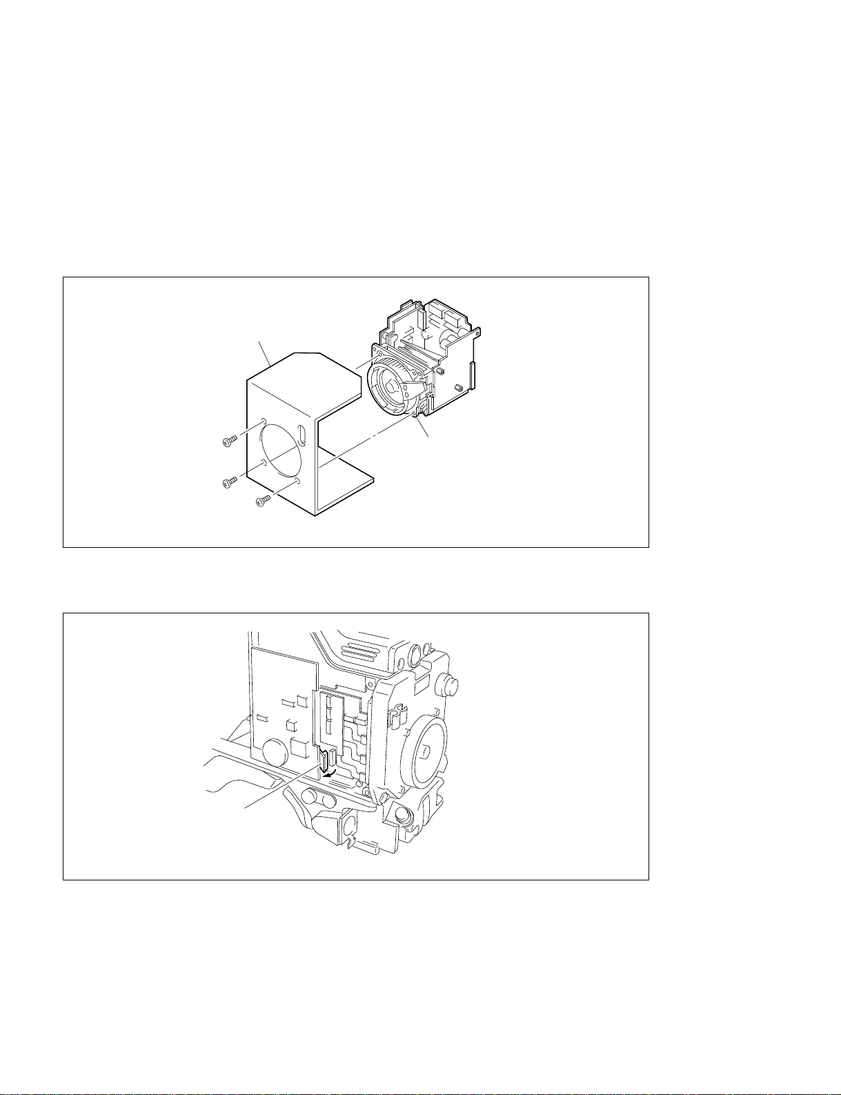
1-3. Replacing CCD Unit .............................................................................1-1 (E)
1-3-1. Description on CCD Block Number ....................................1-1 (E)
1-3-2. Replacing CCD Unit ............................................................1-2 (E)
1-3-3. Disconnecting/Connecting Flexible Card Wire ...................1-5 (E)
1-3-4. Positioning Adjustment for Filter Knobs .............................1-6 (E)
1-4. Modifying Board...................................................................................1-7 (E)
1-4-1. Modifying VDA-31 Board (Camera Adaptor).....................1-7 (E)
1-4-2. Modifying VA-158 Board...................................................1-8 (E)
1-4-3. Modifying IF-569 Board ......................................................1-9 (E)
1-4-4. Modifying SG-226 Board (Camera Adaptor) ....................1-10 (E)
1-4-5. Replacing ROM .................................................................1-10 (E)
2. Electrical Alignment
2-1. Preparation ............................................................................................2-1 (E)
2-1-1. Equipment Required.............................................................2-1 (E)
2-1-2. Switch Setting of IF-569 Board ...........................................2-1 (E)
2-1-3. Clearing the Reference File..................................................2-1 (E)
2-1-4. Presetting the Operator File .................................................2-1 (E)
2-2. VA Gain Adjustment.............................................................................2-2 (E)
2-3. White Shading Adjustment ...................................................................2-2 (E)
2-4. Black Shading Adjustment....................................................................2-4 (E)
2-5. ND Offset Adjustment ..........................................................................2-4 (E)
2-6. Storing the Reference File.....................................................................2-5 (E)
2-7. Storing the Operator File.......................................................................2-6 (E)

2 (E) HKC-7081
3. Setup Menu
3-1. Setup Menu ...........................................................................................3-1 (E)
3-1-1. Operation Menu ...................................................................3-3 (E)
3-1-2. Paint Menu ...........................................................................3-7 (E)
3-1-3. Maintenance Menu .............................................................3-11 (E)
3-1-4. File Menu ...........................................................................3-14 (E)
3-1-5. Diag Disp Menu .................................................................3-15 (E)
3-1-6. SYS Config Menu ..............................................................3-16 (E)
4. Spare Parts
4-1. Notes on Repair Parts ............................................................................4-1 (E)
4-2. Exploded View ............................................................................................4-2
4-3. Electrical Parts List .....................................................................................4-3
5. Semiconductor Pin Assignments
6. Block Diagrams
Block Diagram Index ..................................................................................6-1
CCD Block ..................................................................................................6-2
PA-173 ........................................................................................................6-3
DU-1............................................................................................................6-3
TG-209 ........................................................................................................6-4
DR-376 ........................................................................................................6-5
7. Schematic Diagrams
Schematic Diagram Index ...........................................................................7-1
Location of Printed Circuit Boards .............................................................7-1
TG-209 ........................................................................................................7-3
DR-376 ........................................................................................................7-4
DU-1............................................................................................................7-7
PA-173 ........................................................................................................7-8
CN-1674 ....................................................................................................7-10

3 (E)
HKC-7081
8. Board Layouts
Board Layout Index.....................................................................................8-1
TG-209 ........................................................................................................8-3
DR-376........................................................................................................8-5
DU-1............................................................................................................8-7
PA-173 ........................................................................................................8-9
CN-1674....................................................................................................8-11


5 (E)
HKC-7081
Purpose of this manual This manual is the installation and maintenance manual for CCD Modification Unit
HKC-7081.
This manual describes the information items necessary when the unit is supplied and
installed, and items that premise the service based on the components parts such as
schematic diagrams, board layouts and spare parts lists, assuming use of system and
service engineers.
Contents The following are summaries of all the sections for understanding the contents of
this manual.
Section 1 Installation
Describes the components that constitute the unit and the procedures to install the
HKC-7081 in the HD color camera HDC-750.
Section 2 Electrical Alignment
Describes electrical adjustment necessary after the HKC-7081 is installed in the
HDC-750.
Section 3 Setup Menu
Describes the setup menu for the modified HDC-750.
Section 4 Spare Parts
Describes electrical parts list for every circuit board.
Section 5 Semiconductor Pin Assignments
Describes function diagrams and pin names of semiconductors used in the unit.
Section 6 Block Diagrams
Describes CCD overall block diagram and block diagrams for every circuit board.
Section 7 Schematic Diagrams
Describes schematic diagrams for every circuit board.
Section 8 Board Layouts
Describes board layouts for every circuit board.
Manual Structure

6 (E) HKC-7081
Related manuals Besides this installation and maintenance manual the following manuals are avail-
able for this unit.
..
..
.HDC-750 Operation Manual (Supplied with HDC-750)
This manual is necessary for application and operation of the HDC-750.
..
..
.HDC-750 Maintenance Manual (Supplied with HDC-750)
This manual describes the information items necessary when the HDC-750 is
supplied and installed, items on maintenance, and items that premise the service
based on the components parts such as alignment, schematic diagrams, board
layouts and spare parts lists, assuming use of system and service engineers. When
servicing the modified camera, see the HKC-7081 installation and maintenance
manual and HDC-750 maintenance manual together.

1-1 (E)
HKC-7081
Section 1
Installation
The HKC-7081 is the modification unit for the HDC-750. By installing the HKC-7081 in the HDC-750, it
can be obtained for the HD signal having 1920 x1080 effective picture elements. To install proceed as
follows.
1-1. Configuration of HKC-7081
Description Q’ty Remarks
CCD unit 1
ROM M27V201-HDCA750-V4.03 and up 1 For IC24/SG-226 board (Camera adapter side)
ROM M27V201-HDC750-V4.03 and up 1 For IC26/IF-569 board
Modification board (with jumper wires) 1 Used when modifying the VA-158 board
Jumper wires 2 Used when modifying the IF-569 and SG-226 boards
1080 label 1 After modification, stick it on an appropriate position.
Installation and maintenance manual 1
1-2. Installation Procedures
This section explains briefly on installation and modification procedures. For more details, refer to the
corresponding section.
1. Replacing CCD unit (Refer to Section 1-3.)
2. Modifying board (Refer to Sections 1-4-1 to 1-4-4.)
3. Replacing ROM (Refer to Section 1-4-5.)
4. Electrical alignment (Refer to Section 2.)
1-3. Replacing CCD Unit
1-3-1. Description on CCD Block Number
Every CCD unit has its own ID number called CCD block number. It shows the CCD block type and
serial number for the CCD block.
The CCD block number label is put in the CCD unit.
Ex.) AHAxxxxx
Serial number for CCD block
CCD block type

1-2 (E) HKC-7081
P3 x6
P3 x6
P3 x6
HKC-7081
Transportation holder
1-3-2. Replacing CCD Unit
c
Never remove or install the CCD unit with the power turned on. Because touching internal harness to the
cabinet or other printed circuit boards during replacement causes shorts or electric hazards.
Prior to replacement, be sure to disconnect the optical cable or the cable connected at the DC IN connec-
tor in addition to turning off the power switch.
1. Remove the three screws, then remove the transportation holder from the HKC-7081.
2. Remove the right and left side panels.
3. Remove the CN-1334 board.
1-3. Replacing CCD Unit
CN-1334

1-3 (E)
HKC-7081
4. Disconnect the flexible card wire. Loosen the four screws and pull out the CCD unit carefully.
n
Regarding connecting/disconnecting the flexible card wire, refer to section 1-3-3.
5. Remove the two setscrews each to remove the ND and CC filter knobs.
Fixture: Allen wrench (width across flat = 0.89 mm)
6. Remove the four bolts to remove the front panel from the CCD unit.
Fixture: Allen wrench (width across flat = 2.5 mm)
B4 x8
B4 x8
CCD unit
Flexible card wire
Front panel
SW3
Bolts
(M3 x8)
CC filter knob
SW3
Bolts
(M3 x8)
Setscrews
(WP2 x3)
Setscrews
(WP2 x3)
ND filter knob
1-3. Replacing CCD Unit

1-4 (E) HKC-7081
K3 x6
B2.6 x4
Driver board
Filter disk unit
n
It is recommendable to perform procedures 7 and 8 in a clean room.
7. Disconnect the connector from the driver board. Remove the two screws (K3 x6) to remove the filter
disk unit. Remove the two screws (B2.6 x4) to remove the driver board.
8. Install the filter disk unit to the HKC-7081 with the two screws which were removed in procedure 4.
Connect the connector from the filter disk unit to the driver board.
m
.Be very careful not to touch the surface of the filter disk unit when installing the HKC-7081.
.Be sure to remove the dust protection tape from the HKC-7081 previously.
9. Install the HKC-7081 to the front panel with the four bolts.
Fixture: Allen wrench (width across flat = 2.5 mm)
Tightening torque: 110 x10_2N.m (11 kgf.cm)
10. Install the ND and the CC filter knobs referring to Section 1-3-4 “Positioning Adjustment for Filter
Knob.”
11. Install the HKC-7081 in the reverse order of removal.
1-3. Replacing CCD Unit

1-5 (E)
HKC-7081
1-3-3. Disconnecting/Connecting Flexible Card Wire
The two flexible card wires are used between the MB-570 board and PA-173 board, MB-570 board and
DR-376 board. Take care not to bend forcedly these flexible card wires. This shorten the wire life.
Disconnecting
1. Turn off the power.
2. Slide portions A in the direction of the arrow to unlock and pull out the flexible card wire.
Connecting
m
.Be careful not to insert the flexible card wire obliquely.
.Check that the conductive surface of the flexible card wire is not soiled with dust.
1. Slide portions A in the direction of the arrow and insert the flexible card wire as far as it will go with
the conductive surface down.
2. Slide portions A in the reverse direction to lock.
A
Conductive surface
A
1-3. Replacing CCD Unit

1-6 (E) HKC-7081
1-3-4. Positioning Adjustment for Filter Knobs
Installing the filter knobs, be sure to perform the following adjustment.
1. Rotate the outer knob shaft until the cross filter can be seen from the lens mount.
2. Align the CC filter knob number A with the mark on the front panel and tighten the two setscrews.
Tightening torque: 20 x10_2N.m (2.0 kgf.cm)
3. Rotate the CC filter knob and check that it moves smoothly.
4. Rotate the inner knob shaft until the clear filter (straight through filter) can be seen from the lens
mount.
5. Align the ND filter knob number 1 with the mark on the front panel and tighten the two setscrews.
Tightening torque: 20 x10_2N.m (2.0 kgf.cm)
6. Rotate the ND filter knob and check that it moves smoothly.
Setscrews
(WP2 x3)
Setscrews
(WP2 x3)
Mark
1-3. Replacing CCD Unit

1-7 (E)
HKC-7081
R122
R215
R219
R229
R322
VDA-31 (B SIDE)
A
B
C
D
E
F
G
H
54321
R113
R213
R216 R217
R218
R313
A
B
C
D
E
F
G
H
54321
VDA-31 (A SIDE)
1-4. Modifying Board
1-4-1. Modifying VDA-31 Board (Camera Adaptor)
Parts Required
Prepare the following resistors because they are not supplied with the unit.
Description Q’ty Sony Part No.
Res, metal chip 15 Z1 1-218-648-11
Res, metal chip 18Z1 1-218-650-11
Res, metal chip 30 Z1 1-218-655-11
Res, metal chip 180 Z1 1-218-674-11
Res, metal chip 820 Z1 1-218-690-11
Res, metal chip 13 kZ1 1-218-719-11
Res, metal chip 1 kZ1 1-218-692-11
Res, metal chip 2.2 kZ1 1-218-200-11
Modification Procedures
1. Remove the VDA-31 board.
2. Desolder the following eleven resistors:
R113, R122, R213, R215, R216, R217, R218, R219, R229, R313, R322
3. Solder an 1 kZmetal film resistor at the trace of R113.
4. Solder a 2.2 kZmetal film resistors at the traces of R122, R229 and R322.
5. Solder a 13 kZmetal film resistor at the trace of R213.
6. Solder a 180 Zmetal film resistor at the trace of R215.
7. Solder an 820 Zmetal film resistors at the traces of R216 and R313.
8. Solder a 30 Zmetal film resistor at the trace of R217.
9. Solder a 15 Zmetal film resistor at the trace of R218.
10. Solder an 18 Zmetal film resistor at the trace of R219.
1-4. Modifying Board

1-8 (E) HKC-7081
1-4-2. Modifying VA-158 Board
Parts Required
Description Q’ty Remarks
Modification board (with jumper wires) 1 Supplied with HKC-7081
Sony bond SC608LVZ _Sony Part No. 7-432-912-52
Res, metal chip 20 kZ3 Sony Part No. 1-218-723-91
Res, metal chip 51 kZ2 Sony Part No. 1-218-733-11
Modification Procedures
1. Remove the VA-158 board.
2. Solder the jumper wires from the modification board to the positions specified by the figure.
3. Stick the modification board on the VA-158 board with Sony bond as shown in the figure.
(Shaded portions)
4. Desolder the following five resistors.
R102, R104, R106, R108, R109
5. Solder 20 kZmetal film resistors at the traces of R102, R104, and R106.
6. Solder 51 kZmetal film resistors at the traces of R108 and R109.
The HDC-750 with the following serial number needs the additional modification as follows.
HDC-750 (UCJ): Serial No.10001 to 10096
Description Q’ty Remarks
Res, metal chip 100 kZ1 Sony Part No. 1-218-740-11
Res, metal chip 150 kZ3 Sony Part No. 1-218-744-11
7. Desolder the following four resistors.
R110, R300, R500, R700
8. Solder an 100 kZmetal film resistor at the trace of R110.
9. Solder 150 kZmetal film resistors at the traces of R300, R500, and R700.
1-4. Modifying Board
D
E
F
G
H
LKJCB A
1
2
3
4
5
6
7
VA-158 (B SIDE)
C2 R8
R9 R5
R104
R102 R106
R110
R109
R108
R300R500R700

1-9 (E)
HKC-7081
A
B
C
D
E
F
G
H
54321
IC100
IC36
IF-569 (B SIDE)
1
11
33
34
44
109 144
72 37
36
1
73
108
2212
23
1-4-3. Modifying IF-569 Board
Perform the following modification only when the suffix number of the IF-569 board is -11 or -12.
Parts Required
Description Q’ty Remarks
Jumper wire 1 l = 30 mm
Sony bond SC608LVZ _Sony Part No. 7-432-912-52
Modification Procedures
1. Remove the IF-569 board.
2. Solder the jumper wire between pin 119 of IC100 and pin 16 of IC36.
3. Stick the jumper wire with Sony bond as shown in the figure. (Shaded portion)
1-4. Modifying Board

1-10 (E) HKC-7081
TO Pin 119/IC65
1
2
3
4
5
ABC
IC71
23 33
11
12
22
44
34
1
SG-226 (B SIDE)
IC65
TO Pin 36/IC71
1
2
3
4
5
ABC
144 109
37
36
1
73
108
72
SG-226 (A SIDE)
1-4-4. Modifying SG-226 Board (Camera Adaptor)
Perform the following modification only when the suffix number of the SG-226 board is -11, -12 or -13.
Parts Required
Description Q’ty Remarks
Jumper wire 1 l = 100 mm
Sony bond SC608LVZ _Sony Part No. 7-432-912-52
Modification Procedures
1. Remove the SG-226 board.
2. Solder the jumper wire between pin 119 of IC65 and pin 36 of IC71.
3. Stick the jumper wire with Sony bond as shown in the figure. (Shaded portion)
1-4-5. Replacing ROM
Replace the two ROMs IC26 on the IF-569 board and IC24 on the SG-226 board of the camera adapter
side with new ROMs supplied with HKC-7081.
By replacing the ROMs, the contents of setup menu changes. For more details regarding the setup menu,
refer to Section 3.
1-4. Modifying Board

2-1 (E)
HKC-7081
Section 2
Electrical Alignment
This section explains adjustment items required after the
HKC-7081 is installed.
Perform the following adjustments with setup menu.
Regarding the setup menu operation, refer to Section 3.
2-1. Preparation
2-1-1. Equipment Required
Measuring equipment
.Oscilloscope (band-width: more than 300 MHz)
Tektronix 2465B or equivalent
.HDTV analog waveform monitor
Tektronix 1735HD/1730HD or equivalent
Peripheral equipment
.HD camera control unit HDCU-700A
.Master setup unit MSU-700 (HKCF-700 should
has been installed.)
Tools
.Extension board EX-512
Sony Part No. A-8273-247-A
.Pattern Box PTB-500
Sony Part No. J-6029-140-B
.Grayscale chart (16:9)
Sony Part No. J-6394-080-A
12345678
2-1-2. Switch Setting of IF-569 Board
1. Turn off the power, then remove the IF-569 board.
2. Set the switch S1 on the IF-569 board as shown below.
3. Restore the IF-569 board, then turn on the power. (The
data stored inside the RAM will be cleared.)
4. Restore the switch setting of S1 on the IF-569 board as
shown below.
2-1-3. Clearing the Reference File
Perform the following operation with setup menu.
MENU: File
PAGE: Reference File
ITEM: Clear File
(Press the MENU SEL switch to clear the reference file.)
2-1-4. Presetting the Operator File
Perform the following operation with setup menu.
MENU: Operation
PAGE: Operator File
ITEM: Preset
(Press the MENU SEL switch to preset the operator file.)
12345678

2-2 (E) HKC-7081
A
10uS
50m B
W
L
A
2-2. VA Gain Adjustment
Equipment: Oscilloscope
Object: Grayscale chart
Preparations
.Extend the VA-158 board.
.Shoot the grayscale chart which is well-maintained
(reflectance of 89.9%) so that the chart frame is aligned
with the underscanned monitor frame.
(F8, 2000 lx, 3200 K)
.Settings for MSU-700
CLOSE button →OFF (dark)
ECS/SHUTTER ON button →OFF (dark)
Adjustment Procedures
1. VA OUT R level adjustment
Test Point: TP17/extension board
Adjustment Point: 1RV300/VA-158
Specification: A = 400 ±4 mV
2. VA OUT G level adjustment
Test Point: TP11/extension board
Adjustment Point: 1RV500/VA-158
Specification: A = 400 ±4 mV
3. VA OUT B level adjustment
Test Point: TP5/extension board
Adjustment Point: 1RV700/VA-158
Specification: A = 400 ±4 mV
Resetting after Adjustment
.Return the switches to their previous positions.
2-3. White Shading Adjustment
Equipment: Analog waveform monitor
Test Point: TEST OUT connector
Object: Full white pattern
Note
When performing the white shading adjustment, make sure
the following conditions are proper. If not, adjustment can
not be complete.
.White pattern is not uneven.
.Luminance is correctly adjusted.
.Iris and zoom control of the lens are correctly adjusted.
Preparations
.Connect the waveform monitor to the TEST OUT
connector of the unit.
.Y/RGB switch (at the top of the side panel) →Y
.Setting for MSU-700
KNEE OFF button →OFF (lit)
.Shoot the fully occupied white area of the white pattern
on the underscanned monitor frame.
.Iris of the lens: A = 600 ±20 mV (at F5.6 to F8)
(If a lens aperture is greater than F8, adjust the light
amounts with shutter.)
.Lens Focus: ∞
.Lens Extender/Shrinker: x2, x0.8 →OFF
.Set the setup menu as follows.
MENU: Operation
PAGE: Battery/D56
ITEM: Lens File
(Select the file in accordance with the lens attached. If
there is no appropriate file, select NO OFFSET, then
change the name of lens with MSU.)
2-2. VA Gain Adjustment
2-3. White Shading Adjustment
Other Sony Control Unit manuals

Sony
Sony PWS-110PR1 User manual

Sony
Sony MSU-900 User manual

Sony
Sony BVE-700 User manual

Sony
Sony PDBK-L1500 User manual

Sony
Sony RM-B170 User manual

Sony
Sony DNUR-SY3 User manual

Sony
Sony MB0402C2 User manual

Sony
Sony CBK-UPG02 User manual

Sony
Sony BKS-R1617 User manual

Sony
Sony CCP-8000 Series User manual
Popular Control Unit manuals by other brands

Burster
Burster DIGIFORCE 9311 Operation manual

Mitsubishi Electric
Mitsubishi Electric QJ71MT91 user manual

salmson
salmson Easy Control MS-L 2x4kW Installation and starting instructions

Wisi
Wisi MINI OM 11 operating instructions

Samson
Samson 3246 Mounting and operating instructions

Fenwal
Fenwal 35-70 Series manual