Mannayan Trikombin User manual

©2019 Mannayan GmbH + Co KG
User Manual
Software Version 5.0.1.#3
The RIMENSIONAL Device
of Bioresonance

© 2019 Mannayan GmbH + Co KG Page 2 User Manual Trikombin
This user manual is exclusively provided for the TRIKOMBIN purchaser. It is not permitted
to provide this manual or extracts of it by means of printing, handwriting or in any other form
to a third party.
TRIKOMBIN is a legally protected Community Trade Mark. The unauthorised use of the
Trademark is prohibited.

User Manual Trikombin Page 3 ©2019 Mannayan GmbH + Co KG
Table of Contents
1. Introduction......................................................................................................................................7
2. Important Notices.............................................................................................................................7
2.1 Safety Instruction .......................................................................................................................7
2.2 Unpacking ..................................................................................................................................8
2.3 Packaging and Transportation....................................................................................................8
2.4 Designated Usage.......................................................................................................................8
2.5 Maintenance ...............................................................................................................................9
2.6 Mains Voltage............................................................................................................................9
2.7 Mains Input Fuses ......................................................................................................................9
3. Identification of Operating Elements.............................................................................................10
3.1 Front Side of the Trikombin.....................................................................................................10
3.2 Back side of the Trikombin......................................................................................................10
4. Before Initial Operation .................................................................................................................11
4.1 Initial Preparation of the Device Directly after Transportation ...............................................11
4.2 Preparing the Antenna..............................................................................................................11
4.3 Connecting the Trikombin .......................................................................................................11
4.4 Connecting the Antenna...........................................................................................................12
4.5 Connecting the Electrode Cables .............................................................................................12
4.6 Connecting Output Brass Cups ................................................................................................12
4.7 Connecting Additional Devices ...............................................................................................13
5. Operating the Trikombin................................................................................................................15
5.1 Handling the Rechargeable Batteries.......................................................................................15
5.2 Turning the Trikombin On.......................................................................................................15
5.3 Switching the Trikombin Off...................................................................................................15
5.4 Charging the Trikombin...........................................................................................................15
5.5 Handling the Brass Cups..........................................................................................................16
6. Handling the Program Surface.......................................................................................................17
6.1 Overview..................................................................................................................................17
6.2 Basic Operation........................................................................................................................17
6.2.1 Overview...........................................................................................................................17
6.2.2 Setting Values with the Rotary Encoder ...........................................................................17

© 2019 Mannayan GmbH + Co KG Page 4 User Manual Trikombin
6.2.3 Other Functions of the Rotary Encoder ............................................................................17
7. Operating Modes............................................................................................................................19
7.1 Start Mode................................................................................................................................19
7.1.1 Cable Tester ......................................................................................................................20
7.1.2 General Settings ................................................................................................................21
Language................................................................................................................................21
Brightness of the Touchscreen...............................................................................................21
Testing –Standard Setting for the Operation Mode Testing .................................................21
Application - Default Setting for the Application..................................................................21
Date and Time........................................................................................................................21
Speaker Volume of Acoustic Signals.....................................................................................22
7.1.3 Operator Presets ................................................................................................................22
Selecting Presets ....................................................................................................................22
7.1.4 Installing Firmware Updates, Licenses and Libraries.......................................................22
7.2 Testing Mode ...........................................................................................................................24
7.2.1 Important Elements of the Testing Screen........................................................................24
7.2.2 Function Keys ...................................................................................................................25
7.2.3 Navigation Bar ..................................................................................................................27
7.2.4 Options for Directly Loading a Frequency Program ........................................................28
7.2.5 Modifying Frequency Programs .......................................................................................29
7.2.6 Adjusting the Pitch............................................................................................................30
Operating Elements of the Dialogue “Adjust Pitch” .............................................................30
7.2.7 Adding Frequency Programs to the Application Mode ....................................................31
7.2.8 Editing Frequency Programs of the Application List in the Testing Mode ......................32
Option 1: Selection via the Navigation Bar ...........................................................................32
Option 2: Call the Testing Mode during the Running Application........................................32
Applying the Modifications ...................................................................................................32
7.2.9 Saving User-defined Programs .........................................................................................33
7.2.10 Terminator Feature..........................................................................................................33
7.2.11 Foot Switch .....................................................................................................................34
Connecting the Foot Switch...................................................................................................34
Switch Functions....................................................................................................................34
7.3 Application Mode ....................................................................................................................35
7.3.1 Overview...........................................................................................................................35
7.3.2 Important Elements of the Application Mode...................................................................35

User Manual Trikombin Page 5 ©2019 Mannayan GmbH + Co KG
7.3.3 Contents of the Columns of the Application List .............................................................36
7.3.4 Adding Frequency Programs to the Application List .......................................................36
7.3.5 Selecting a Frequency Program ........................................................................................37
7.3.6 Execution of the Application List .....................................................................................37
7.3.7 Acoustic Signals................................................................................................................38
7.3.8 Moving a Frequency Program...........................................................................................38
7.4 Working with Pulse/Wobble-Synchronization ........................................................................39
7.4.1 Connection of the pulse meter ..........................................................................................39
7.4.2 Starting the Pulse/Wobble-Synchronisation .....................................................................39
7.5 Working with Diamond Shield Chip Cards .............................................................................41
7.5.1 Overview...........................................................................................................................41
7.5.2 Supported Diamond Shield Devices .................................................................................41
7.5.3 Opening the Chip Card Editing Dialogue .........................................................................41
7.5.4 Displaying the Frequency Programs of a Sequence..........................................................42
7.5.5 Importing a Sequence or a Frequency Program from the Chip Card to the Application
List .............................................................................................................................................42
7.5.6 Moving a Sequence...........................................................................................................42
7.5.7 Copying Frequency Programs from the Application List to the Chip Card .....................42
7.6 Working with Libraries............................................................................................................44
7.6.1 Overview...........................................................................................................................44
Chains of Frequency Programs ..............................................................................................44
7.6.2 Searching Libraries ...........................................................................................................44
Entering a Search Term..........................................................................................................44
Selecting a Desired Chain ......................................................................................................45
7.6.3 Using the Selected Chains in the Testing Mode ...............................................................45
7.6.4 Loading a Chain via its Chain Number.............................................................................45
7.6.5 Removing a Chain from the Testing Mode.......................................................................46
8. Technical Specifications ................................................................................................................47
8.1 General .....................................................................................................................................47
8.2 Connections..............................................................................................................................47
8.3 Characteristics of the Output Signals.......................................................................................47
9. Declaration of Conformity .............................................................................................................49
Accessories.........................................................................................................................................51

© 2019 Mannayan GmbH + Co KG Page 6 User Manual Trikombin

User Manual Trikombin Page 7 ©2019 Mannayan GmbH + Co KG
1. Introduction
Trikombin is a powerful frequency generator with 3 outputs, which are mutually independent
and isolated from each other. It is equipped with rechargeable batteries, which enable an
independent operation for approximately 8 hours.
This manual describes the device with the software version 5.0.1#3.
2. Important Notices
2.1 Safety Instruction
•Never plug, under no circumstances, a banana plug into a
power outlet.
•Always plug the earthing cable firstly into Trikombin or into the
antenna and only then insert the cable into a power outlet.
•Do not use the device on people with a heart pacemaker.
•Do not use the device near the eye area.
•Do not connect the 3 frequency outputs in series.
•Do not open the housing of the device. There are no serviceable
parts inside.
•Use only the provided fuses (3,15AT). In no case, greater fuses
may be used.
•Use only the supplied AC adapter.
•Remove both fuses before transportation.
•Be careful while transporting the Trikombin, because the brass
cups or lids might fall out.
•Keep the Trikombin clean and most importantly dry (wiping with
a damp cloth is permitted).
•Please make certain to secure the Trikombin to prevent it from
falling down. If someone pulls the connecting cables with great
force, the device can be brought down, despite its non-slip
rubber feet.
To ensure safety and prevention of damage to health, as well as damage to the device,
complying with the operating instructions is essential. Mannayan GmbH & Co KG
assumes no liability in case of misuse.

© 2019 Mannayan GmbH + Co KG Page 8 User Manual Trikombin
2.2 Unpacking
Before using the device, please check for the completeness of the supplied accessories:
1. Power adapter
2. 2 fuse holder and 2 micro fuses 3,15AT
3. Antenna housing
4. Antenna foot with matching fixing screws (2 pcs)
5. 3 cables (red, green, blue) with banana plugs
6. 1 cable with BNC connector
7. 2 earthing cables
8. 3 hand electrodes
9. Large metal cup tray cover (mounted)
10. 3 brass cups with lids (underneath the large metal cup tray cover).
After unpacking, please check the device thoroughly for any possible transportation related
mechanical damage and loose inner parts. If a transport damage has occurred, please
contact your supplier immediately. The device must not be used in this case.
2.3 Packaging and Transportation
Please retain the original box for possible future transportation. Any damage due to improper
packaging is excluded from the warranty.
Please note that both fuses (back side of device) must be removed before any
transportation.
The device should be stored in dry, enclosed spaces. If the device is stored or transported
under extreme temperatures, it should be left to acclimatize for at least 2 hours before it is
put into operation.
2.4 Designated Usage
Frequency therapy is a form of regulative therapy and is not yet part of conventional
medicine-based scientific research and therefore not yet recognized. The terminology of the
individual programs does not represent specific claims of efficacy. The device can be used
to enhance the subjective well-being.
The device is to be operated in clean, dry places. It must not be operated in dust or extreme
moisture, in places with danger of explosion or in places with aggressive chemical
influences.
The device should be protected from direct sunlight.

User Manual Trikombin Page 9 ©2019 Mannayan GmbH + Co KG
The permissible temperature range –while in operation –varies from +15 °C to +30 °C.
During storage or transportation, the ambient temperature can range between -20 °C and
+70 °C. If condensation occurs during storage or transportation, the device must be
acclimated for about 2 hours and dried by means of an appropriate circulation. Thereafter,
the operation is permitted.
Nominal data with tolerance disclosures are valid after a warm-up time of at least 30 minutes
at an ambient temperature of 23° C. All values without tolerance disclosures are
recommended values of an average device.
2.5 Maintenance
The outside of the appliance should be cleaned regularly with a soft, lint-free duster. Please
make sure that the device is turned off and disconnected from the power supply, before you
clean it.
Cleaning the device or its parts with alcohol or other solvents is not allowed, except for
cleaning the removable brass cups.
The display may only be cleaned using water or a suitable glass cleaner (but not with alcohol
or other washing solvents).
The coloured banana cables, the ground cable and the two earthing cables should be
checked regularly with the built-in cable tester.
2.6 Mains Voltage
The device operates with an AC voltage of 100 V to 240 V with a frequency from 47 to 63 Hz.
A supply mains voltage switching is not necessary.
2.7 Mains Input Fuses
The device has 2 fuses: 3,15AT. One fuse (fuse A) ensures the charge cycle, while the
second fuse (fuse B) ensures normal operation.
Only micro fuses with 3,15AT may be used.
If a fuse is blown repeatedly, a repair is needed. The device is to be shut down in this case.
© 2019 Mannayan GmbH + Co KG Page 10 User Manual Trikombin
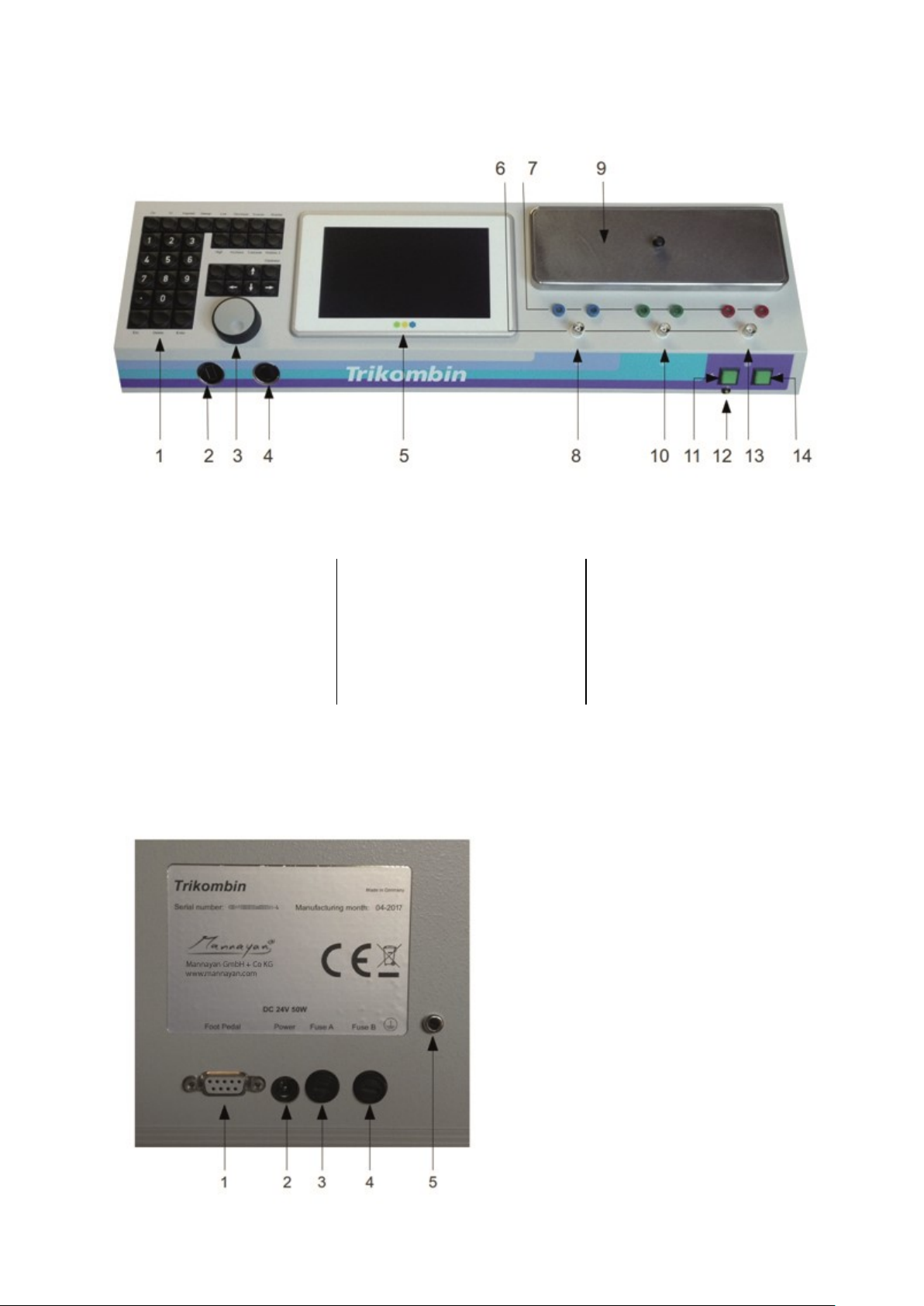
3. Identification of Operating Elements
3.1 Front Side of the Trikombin
1. Keypad
2. Ethernet socket
3. Rotary encoder
4. USB slot
5. Touchscreen
6. BNC sockets
7. Banana sockets
8. Channel I
9. Cup tray cover
10.Channel II
11.Charging switch
12.Charging-LED
13.Channel III
14.Power switch
3.2 Back side of the Trikombin
The illustration below shows the technical connections and elements of the back side
1: Foot switch connector
2: DC terminal
3: Fuse A
4: Fuse B
5: Earthing socket

User Manual Trikombin Page 11 ©2019 Mannayan GmbH + Co KG
4. Before Initial Operation
4.1 Initial Preparation of the Device Directly after Transportation
Both fuses have been removed for transportation. Please insert both fuse holders with the
provided micro fuses (3,15AT) into the fuse sockets (Fuse A and Fuse B) on the back side
of the device. The fuse holder can be held by means of a bayonet catch. Insert the fuse
holder with the pre-assembled fuse completely into the socket and fasten it with a ¼ turn to
the right. Use an appropriate screwdriver for this task.
The touchscreen is covered with a protective foil. Please, remove the protective foil before
turning on the device for the first time.
The cup tray cover is secured with two adhesive tapes during transportation. Please remove
the two tapes as well.
4.2 Preparing the Antenna
The foot of the antenna is supplied with 2 screws, with which it should be attached to the
antenna. Please note, that the antenna housing is plastic. Therefore, you should not use
excessive force, while tightening the screws.
4.3 Connecting the Trikombin
1. Connect the power adapter to the charger socket of the Trikombin and the supplied
power cord to a mains power outlet (AC outlet).
2. Please verify if the power outlet is suitably earthed with the supplied power outlet test
instrument. Only if that is ensured, take one of the two supplied earthing cables.
Please FIRST insert the banana plug into the earth socket of the Trikombin (back
side). THEN insert the Schuko plug into a suitable power outlet. Connect both
earthing cables to the same outlet with the help of a splitter or to two accompanying
outlets –both earthing cables must be assembled within the same circuit.
3. Caution: No other cables must be used for earthing. The earthing cables of the
Diamond Shield Zapper are NOT suited as well! A functional suitable earthing is
precondition for operating the Trikombin! Please check all cables with the cable
tester regularly (see chapter 7.1.1 Cable Tester)
4. If using an external footswitch (optional accessory):
Insert the plug of the foot switch into the corresponding socket on the back side of
the device. Then turn both screws of the plug lightly (!) to secure the plug from falling
out.
5. The output signals are available on the BNC-sockets as well as on the left banana
sockets. A series circuit of the outputs is not allowed.
©2019 Mannayan GmbH + Co KG Page 12 User Manual Trikombin
Please note: in principle, every frequency output has TWO signals. One signal (“hot” signal)
carries the actual information. It is connected on the brass cup, the left banana sockets, as
well as on the inner pin of the BNC socket. The second signal (“cold” signal) is used as
reference and is connected on the outer pin of the BNC socket.
4.4 Connecting the Antenna
Please verify if the power outlet is suitably earthed with the supplied power outlet test
instrument. Only if that is ensured, take one of the two supplied earthing cables. Please
FIRST insert the banana plug into the earth socket of the Antenna. THEN insert the Schuko
plug into a suitable power outlet.
4.5 Connecting the Electrode Cables
Insert the banana plugs of the coloured cables each in the LEFT socket of the Trikombin
and the other end in the supplied hand electrode.
An optional available ampoule tapper is connected via a random cable with a banana plug
on the blue socket on the RIGHT side.
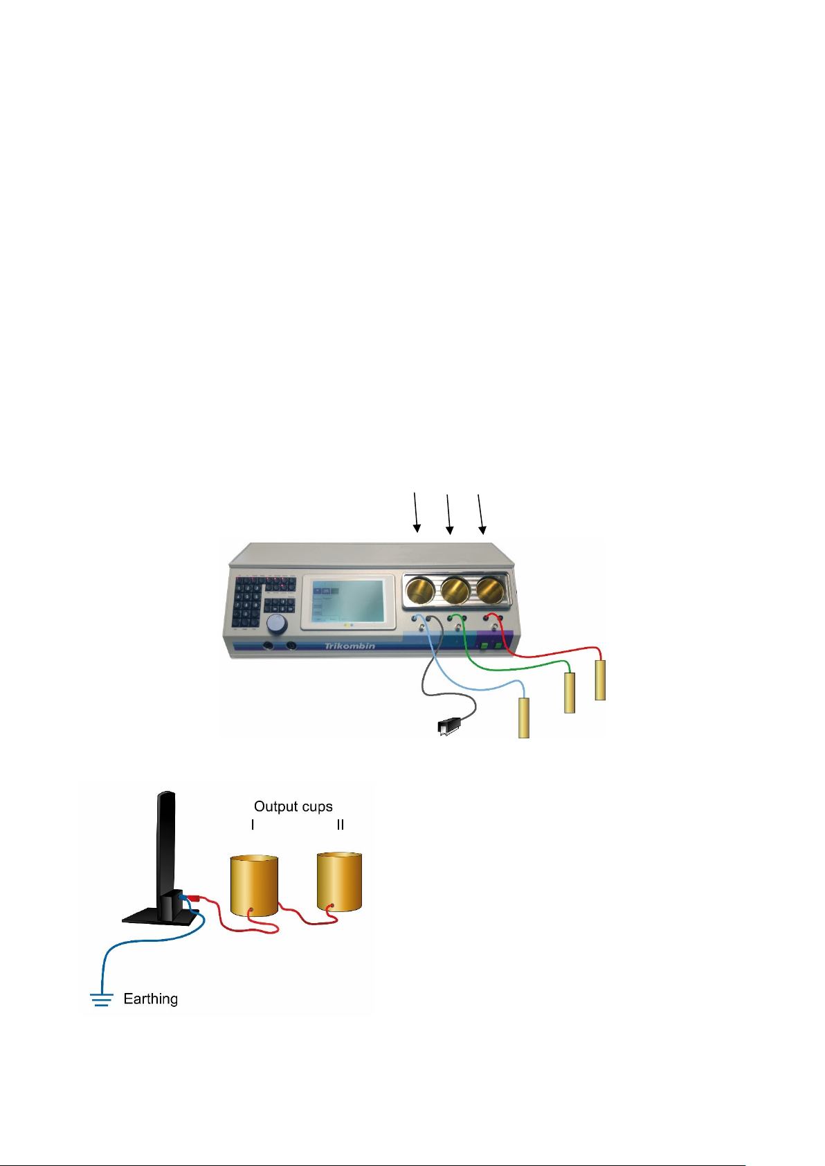
4.6 Connecting Output Brass Cups
Optional available output cups are connected
after the antenna. The banana plug is inserted on
the back side of the antenna into the earthing
cable.
Attention: If the cups are attached between
the Antenna and the earthing cable a loss of
efficiency of the antenna is caused!
Input Cups I II III
User Manual Trikombin Page 13 ©2019 Mannayan GmbH + Co KG
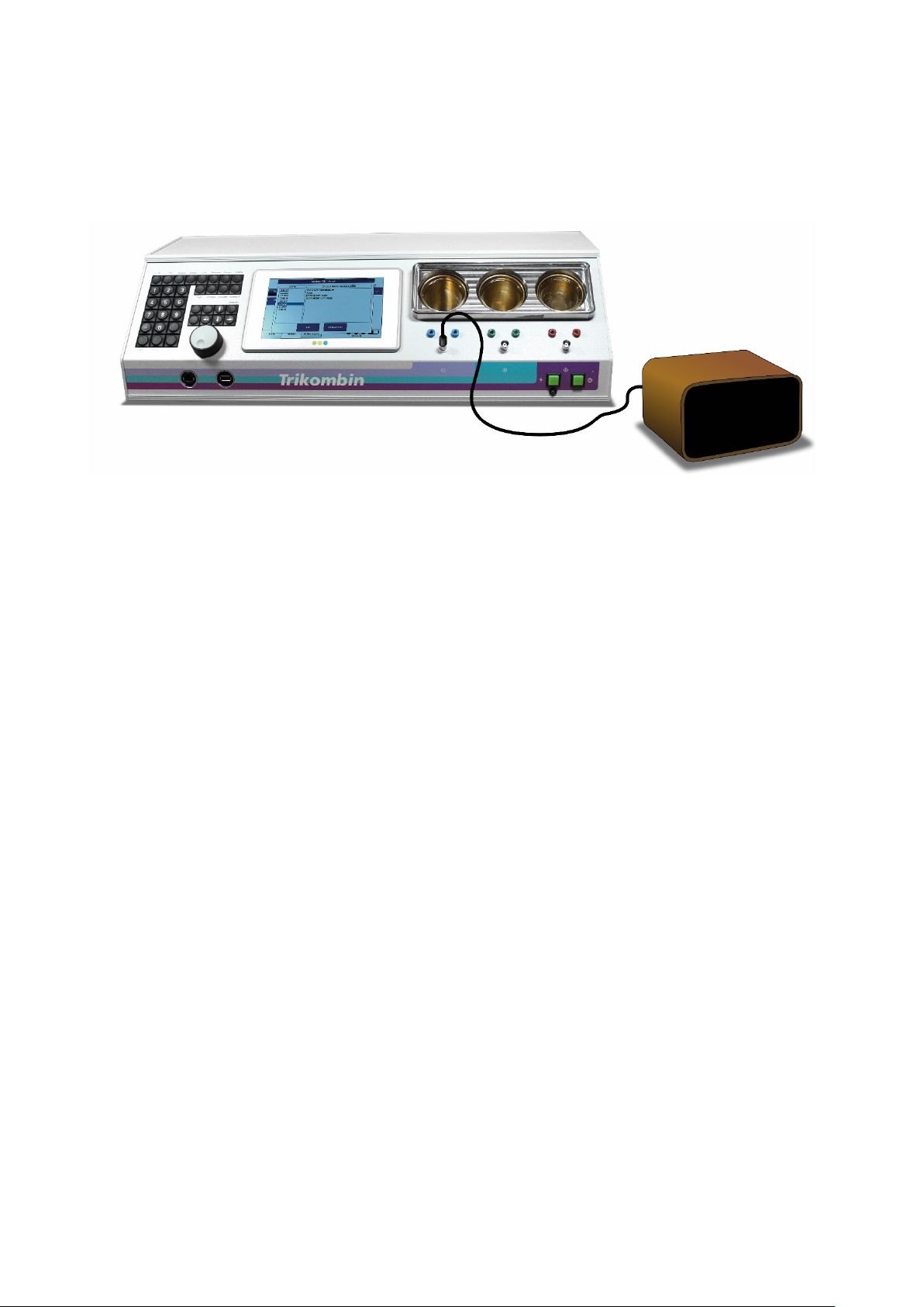
4.7 Connecting Additional Devices
The BNC sockets of the 3 channels can be used to connect suitable additional devices, such
as optionally available loudspeakers.

©2019 Mannayan GmbH + Co KG Page 14 User Manual Trikombin

User Manual Trikombin Page 15 ©2019 Mannayan GmbH + Co KG
5. Operating the Trikombin
5.1 Handling the Rechargeable Batteries
When storing the device, the rechargeable batteries should be recharged every six months.
The rechargeable batteries can be partially charged –it does not cause any damage.
As soon as the battery charge indicator in the display lights up red, the batteries should be
recharged.
Operating the Trikombin is not possible during the charging process. The device charges
faster when it is turned off.
If the device is not in operation for a longer period of time, the batteries should be previously
recharged completely.
The rechargeable batteries are integrated and need not be removed for transportation.
However, both fuses must be removed before transportation.
To achieve an optimal and radiation-free operation, the device should be disconnected from
the main power supply.
5.2 Turning the Trikombin On
Press the power switch. The power switch lights green. While the Trikombin boots, you can
see the product name on the touchscreen. Approximately after 20 seconds, the start screen
appears and the device is ready.
5.3 Switching the Trikombin Off
To turn off, simply press the power switch so that its LED is not lit. The Trikombin must not
be shut down.
5.4 Charging the Trikombin
The Trikombin has an electronic charger for the rechargeable batteries, which runs
independently from the touchscreen (operator terminal). First, please make sure that the
power adapter is connected to the mains voltage and the charging socket of the Trikombin.
Now press the charging switch. For a brief moment, they both light up: the charging switch
and the underlying yellow charging-LED. Afterwards the two LEDs display the charge status
as follows:
a) The yellow charging-LED lights up, charging switch is dark (off): batteries are charging.
b) The yellow charging-LED is dark, charging switch lights up: batteries are fully charged.
During the charging process, the operator terminal can be turned on by pressing the power
switch. During charging it is impossible to activate the frequency outputs or to leave the
mode “Start”.
If the operator terminal is turned on during the charging process, the batteries will be charged
normally. Under certain circumstances the charging circuitry doesn’t detect when the

©2019 Mannayan GmbH + Co KG Page 16 User Manual Trikombin
batteries are fully charged, as the turned on/activated operator terminal draws power from
the batteries. This however has no influence on the safety or on the battery lifespan.
A full charge cycle takes approximately 3 to 4 hours. A partial loading or unloading is
permitted and has no negative impact on the battery lifespan or its capacity. As soon as the
battery charge indicator in the display lights up red, the batteries should be recharged.
5.5 Handling the Brass Cups
A brass cup is assigned to each output channel. The output signal is fed via the brass cup
and then to the left banana socket and the BNC socket.
The brass cups can be removed, if necessary (e.g. for cleaning purposes). To enable this,
one must remove the large cup tray cover and the covers of the brass cups. Afterwards each
brass cup can be pulled out with little effort.
All three brass cups are identical, so they can be safely exchanged between the channels.
For reconnecting the brass cups, make sure that they are fully inserted. They must be put
in with some force, to close the contact. The contact is made only on the last 5 millimetres
of the downward movement.

User Manual Trikombin Page 17 ©2019 Mannayan GmbH + Co KG
6. Handling the Program Surface
6.1 Overview
The Trikombin software offers three main modes. These are selected using the tabs at the
bottom of the screen:
•Start
A new session can be started and certain configurations can be made in this screen.
This mode usually is only needed after switching on the device or when changing a
session.
•Testing
Frequency programs can be loaded and adapted as necessary here. If appropriate
frequency programs were found, they can be transferred to the Application Mode.
•Application
The selected and individualised frequency programs are executed here.
6.2 Basic Operation
6.2.1 Overview
Trikombin is operated using the touchscreen, the rotary encoder and the keypad.
The screen of the operator terminal is designed as a touchscreen. You can trigger the
actions by gently pressing on an area of the screen with a finger or any blunt object.
The keypad keys operate as you are used to from your computer, with exception of the keys,
that have a little lamp.
These keys with little lamps and their functions are described in section 7.2.2 Function Keys.
6.2.2 Setting Values with the Rotary Encoder
The encoder enables to quickly change numerical values.
Simply tap your finger on the numeric value you want to change. The outline of the value is
shown in bold, indicating that the value is active.
Now you can change the value using the rotary encoder. A faster turn causes a greater
change in a value.
6.2.3 Other Functions of the Rotary Encoder
The rotary encoder can also be used to
•scroll touchscreen contents
to change the selected entry in a list.

©2019 Mannayan GmbH + Co KG Page 18 User Manual Trikombin

User Manual Trikombin Page 19 ©2019 Mannayan GmbH + Co KG
7. Operating Modes
7.1 Start Mode
1. Buttons to switch between users (presets)
2. Quick start buttons for frequency programs
A frequency program can be assigned to each of the buttons. When pressing the
button, the frequency program is loaded and the system changes into the Testing
Mode.
The assignment is made in the Testing Mode: Press the button “More...” and then
press “Assign to quick start...”.
3. Quick start buttons for applications
An application list can be assigned to each of the buttons. When pressing the
button, the corresponding applications are loaded and the system changes into the
Application Mode.
The assignment is made in the Application Mode: Press the button “More…” and
then press “Assign to quick start…”
4. Tabs to select the main modes Start, Testing and Application.
5. Activity state of the generators (on or off)
oOn: all three lamps of the touchscreen flash green
oOff: all three lamps of the touchscreen are black
6. Time display
7. Battery charge state

©2019 Mannayan GmbH + Co KG Page 20 User Manual Trikombin
8. Button to open the maintenance dialogue
It allows to update the firmware and to install additional licenses.
9. Button to open the settings dialogue
10.Button to start the cable tester
11.Button to start a new session. The following actions occur:
•The Testing Mode will be brought to its initial state. All changes made to the
frequency programs are reset.
•All library chains added to the testing screen are removed.
•The pitch is reset.
•The contents of the Application Mode are deleted.
7.1.1 Cable Tester
All cables in use must be checked regularly with the built-in cable tester.
To do so, please proceed as follows:
1. Select the Start Mode and tap the button “Cable tester…”.
2. Make sure that nothing is connected to the BNC sockets and then confirm the
according message.
3. Then connect the blue banana cable to one of the two blue banana sockets.
4. Now touch with the free end of the blue connector cable the outer metal ring of the
BNC –socket, which is located directly below the blue banana sockets. Keep this
contact for a few seconds.
5. The cable tester now indicates whether there is a sufficient contact and therefore the
cable is intact or defect.
6. To exclude a loose connection, you should bend the cable near the connectors while
you observe the display. It should indicate a steady contact.
7. With the screen buttons “Channel II” and “Channel III” you can switch to the other
channels and test the other cables accordingly.
For testing the earthing cable, plug the banana plug of the earthing cable into a
banana socket and touch the BNC socket with the metal contact of the Schuko plug.
Attention: a functional suitable earthing is precondition for functional usage of
the Trikombin!
8. The black-red cable with a BNC plug can be tested by connecting it to a BNC socket
and touching the banana cable’s red and black ends.
Other manuals for Trikombin
1
Table of contents
Other Mannayan Medical Equipment manuals


