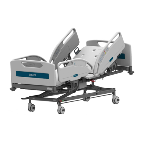
Arjo Enterprise E8000X User manual

746-587_5 • 09/2021
SERVICE MANUAL
Enterprise E8000X (E8X)
For internal use only

Page i
PREFACE
Read and understand this manual before attempting to service or repair the equipment.
This manual is intended for use by Arjo approved service technicians. The manual may be
provided to a customer in response to customer requirements, but in no event will Arjo be
responsible for any service or repair performed by customers.
Warnings, Cautions and Notes
WARNINGS given in this manual identify possible hazards in procedures or conditions which,
if not correctly followed, could result in death, injury or other serious adverse reactions.
Cautions given in this manual identify procedures or conditions which, if not correctly
followed, could result in equipment failure or damage.
Notes given in this manual (indicated by ) are used to explain or amplify a procedure or
condition.
indicates optional features or functions not available on all beds.
General Warnings
Design Policy and Copyright ® and ™ are trademarks belonging to the Arjo group of
companies.
© Arjo 2019. As our policy is one of continuous improvement, we reserve the right to
modify designs without prior notice. The content of this publication may not be copied
either whole or in part without the consent of Arjo
WARNING
Before starting any service or maintenance procedures, ensure that the
equipment has been adequately decontaminated.
Electrical equipment can be hazardous if misused. Obey all safety
instructions.
Do not use electrically powered beds in the presence of flammable gases,
such as anaesthetic agents.
The bed and its sub-assemblies are very heavy and appropriate precautions
must be taken to avoid injury when moving or lifting them.
Disconnect the bed from the mains supply before starting any maintenance
activity. The bed will still operate on battery power unless the function is
locked on the Attendant Control panel (ACP).
Do not remove protective covers or open electrical enclosures while the bed
is connected to the mains supply.

Page ii
TABLE OF CONTENTS
CHAPTER 1
Introduction . . . . . . . . . . . . . . . . . . . . . . . . . . . . . . . . . . . . . . . . . . . . . . . . . . . . . . . . 1
About This Manual. . . . . . . . . . . . . . . . . . . . . . . . . . . . . . . . . . . . . . . . . . . . . . . . . 1
Product Description . . . . . . . . . . . . . . . . . . . . . . . . . . . . . . . . . . . . . . . . . . . . . . . . 2
CHAPTER 2
Decontamination . . . . . . . . . . . . . . . . . . . . . . . . . . . . . . . . . . . . . . . . . . . . . . . . . . . . 5
Cleaning. . . . . . . . . . . . . . . . . . . . . . . . . . . . . . . . . . . . . . . . . . . . . . . . . . . . . . . . . 5
Disinfecting . . . . . . . . . . . . . . . . . . . . . . . . . . . . . . . . . . . . . . . . . . . . . . . . . . . . . . 5
CHAPTER 3
Preventive Maintenance . . . . . . . . . . . . . . . . . . . . . . . . . . . . . . . . . . . . . . . . . . . . . . 7
General . . . . . . . . . . . . . . . . . . . . . . . . . . . . . . . . . . . . . . . . . . . . . . . . . . . . . . . . . 7
Castors and Brakes . . . . . . . . . . . . . . . . . . . . . . . . . . . . . . . . . . . . . . . . . . . . . . . . 7
Battery Test . . . . . . . . . . . . . . . . . . . . . . . . . . . . . . . . . . . . . . . . . . . . . . . . . . . . . . 8
CHAPTER 4
Testing . . . . . . . . . . . . . . . . . . . . . . . . . . . . . . . . . . . . . . . . . . . . . . . . . . . . . . . . . . . . 9
Preliminary. . . . . . . . . . . . . . . . . . . . . . . . . . . . . . . . . . . . . . . . . . . . . . . . . . . . . . . 9
Electrical Functions . . . . . . . . . . . . . . . . . . . . . . . . . . . . . . . . . . . . . . . . . . . . . . . . 9
Manual Functions . . . . . . . . . . . . . . . . . . . . . . . . . . . . . . . . . . . . . . . . . . . . . . . . 10
CHAPTER 5
Troubleshooting . . . . . . . . . . . . . . . . . . . . . . . . . . . . . . . . . . . . . . . . . . . . . . . . . . . 11
Fault finding . . . . . . . . . . . . . . . . . . . . . . . . . . . . . . . . . . . . . . . . . . . . . . . . . . . . . 11
Fault Indications. . . . . . . . . . . . . . . . . . . . . . . . . . . . . . . . . . . . . . . . . . . . . . . . . . 11
Fatal Error Troubleshooting . . . . . . . . . . . . . . . . . . . . . . . . . . . . . . . . . . . . . . . . . . 13
Linak Service Data Tool. . . . . . . . . . . . . . . . . . . . . . . . . . . . . . . . . . . . . . . . . . . . . 16
CHAPTER 6
Servicing Instructions . . . . . . . . . . . . . . . . . . . . . . . . . . . . . . . . . . . . . . . . . . . . . . 17
General . . . . . . . . . . . . . . . . . . . . . . . . . . . . . . . . . . . . . . . . . . . . . . . . . . . . . . . . 17
Tools and Equipment. . . . . . . . . . . . . . . . . . . . . . . . . . . . . . . . . . . . . . . . . . . . . . 21
Spares kits . . . . . . . . . . . . . . . . . . . . . . . . . . . . . . . . . . . . . . . . . . . . . . . . . . . . . . 21
Electrical Assembly . . . . . . . . . . . . . . . . . . . . . . . . . . . . . . . . . . . . . . . . . . . . . . . 22
Sub Frame & Sections Assembly . . . . . . . . . . . . . . . . . . . . . . . . . . . . . . . . . . . . 30
Sub Frame Assembly . . . . . . . . . . . . . . . . . . . . . . . . . . . . . . . . . . . . . . . . . . . . . 32
Brake Pedal - Replacement. . . . . . . . . . . . . . . . . . . . . . . . . . . . . . . . . . . . . . . . . 34
Castors - Replacement . . . . . . . . . . . . . . . . . . . . . . . . . . . . . . . . . . . . . . . . . . . . 35
Backup Battery - Replacement . . . . . . . . . . . . . . . . . . . . . . . . . . . . . . . . . . . . . . 40
Mains Lead - Replacement . . . . . . . . . . . . . . . . . . . . . . . . . . . . . . . . . . . . . . . . . 42
Control Box - Replacement . . . . . . . . . . . . . . . . . . . . . . . . . . . . . . . . . . . . . . . . . 44
Deck Junction Box - Replacement. . . . . . . . . . . . . . . . . . . . . . . . . . . . . . . . . . . . 46
Attendant Control Panel - Replacement . . . . . . . . . . . . . . . . . . . . . . . . . . . . . . . 48
Patient Control Unit - Replacement . . . . . . . . . . . . . . . . . . . . . . . . . . . . . . . . . . . 50
Height Actuator - Replacement . . . . . . . . . . . . . . . . . . . . . . . . . . . . . . . . . . . . . . 51
Backrest Actuator - Replacement . . . . . . . . . . . . . . . . . . . . . . . . . . . . . . . . . . . . 53
Thigh Actuator - Replacement . . . . . . . . . . . . . . . . . . . . . . . . . . . . . . . . . . . . . . . 54
CPR Release Handle and Cable - Replacement. . . . . . . . . . . . . . . . . . . . . . . . . 56
Backrest Damper - Replacement. . . . . . . . . . . . . . . . . . . . . . . . . . . . . . . . . . . . . 57
Bed Extension / Bed Stripper - Replacement . . . . . . . . . . . . . . . . . . . . . . . . . . . 60
Head End Split Side Rail - Replacement . . . . . . . . . . . . . . . . . . . . . . . . . . . . . . . 62

Page iii
Foot End Split Side Rail - Replacement. . . . . . . . . . . . . . . . . . . . . . . . . . . . . . . . 66
Split Side Rail Damper - Replacement. . . . . . . . . . . . . . . . . . . . . . . . . . . . . . . . . 67
Side Rail Soft Drop Damper and Bracket - Replacement (Optional) . . . . . . . . . . .69
Roller Buffer - Replacement. . . . . . . . . . . . . . . . . . . . . . . . . . . . . . . . . . . . . . . . . 72
Restoration of Paintwork . . . . . . . . . . . . . . . . . . . . . . . . . . . . . . . . . . . . . . . . . . . 80
Calf section and calf section stay – replacement . . . . . . . . . . . . . . . . . . . . . . . . . 88
Thigh section – replacement . . . . . . . . . . . . . . . . . . . . . . . . . . . . . . . . . . . . . . . . 85
Stabiliser arm – replacement . . . . . . . . . . . . . . . . . . . . . . . . . . . . . . . . . . . . . . . . 86
Radius arm slide mouldings – replacement . . . . . . . . . . . . . . . . . . . . . . . . . . . . . 87
Calf extension sheet – replacement. . . . . . . . . . . . . . . . . . . . . . . . . . . . . . . . . . . 88
Calf ratchet moulding – replacement . . . . . . . . . . . . . . . . . . . . . . . . . . . . . . . . . . 89
Sleeve Bearing – Replacement . . . . . . . . . . . . . . . . . . . . . . . . . . . . . . . . . . . . . . .90
CHAPTER 7
Technical Data . . . . . . . . . . . . . . . . . . . . . . . . . . . . . . . . . . . . . . . . . . . . . . . . . . . . .91
SAFE DISPOSAL OF GAS SPRINGS . . . . . . . . . . . . . . . . . . . . . . . . . . . . . . . . . . .95
ELECTROMAGNETIC COMPATIBILITY . . . . . . . . . . . . . . . . . . . . . . . . . . . . . . . . .96

Enterprise E8000X Service Manual Introduction
Page 1
CHAPTER 1
INTRODUCTION
1 About This Manual
This manual contains information on servicing and maintenance of the Arjo Enterprise®E8000X bed.
The manual comprises the following Chapters:
Chapter 1 Introduction (this chapter): General description of the equipment with an explanation of
the various features available, together with contact details for Arjo around the world.
Chapter 2 Decontamination: recommended procedures for cleaning and disinfecting the
equipment.
Chapter 3 Preventive Maintenance: Details of regular, periodic maintenance actions to ensure
correct operation of the equipment.
Chapter 4 Testing: Serviceability test to verify correct operation of the equipment if function is
suspect or following any maintenance or servicing procedure.
Chapter 5 Troubleshooting: fault symptoms, possible causes and suggested remedial actions.
Chapter 6 Servicing Instructions: Procedures for removal and installation of replaceable parts and
sub-assemblies.
Chapter 7 Technical Data: List of electrical and dimensional data for the equipment and
components.
Instructions for the safe disposal of gas springs.
Information on Electromagnetic Compatibility (EMC) for medical electrical equipment.

Introduction Enterprise E8000X Service Manual
Page 2
2 Product Description
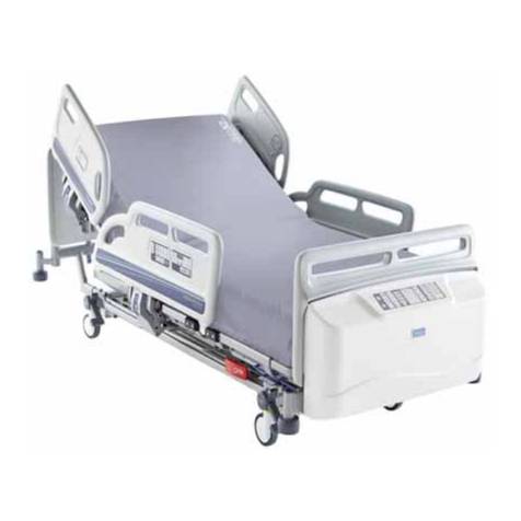
The Enterprise E8000X is an electrically operated acute care medical bed. The bed has multiple
functions to provide the best nursing position for both patient and carer.
2.1 Scope
This service manual covers all Enterprise E8000X models.
2.2 Standard Features
• Four section electrically-operated profiling mattress platform with independent adjustment of
backrest angle, thigh section angle and calf section angle
• Simultaneous adjustment of backrest and thigh sections by pressing one button
(BioContour®)
• Electrically-operated height adjustment
• Electrically-operated Trendelenburg and reverse Trendelenburg tilt.
• Auto-Chair facility
• Split side rails with integrated controls
• Battery backup for all electrical functions
• Removable moulded plastic mattress platform sheets
• Integral 3-position mattress platform extension
• 125mm single wheel castors
• Underbed lights
2.3 Optional Features
• 150mm single or dual wheel castors
• Bedstripper (linen shelf)
• Additional brake pedals at head end
• DIN accessory rails
• Lockable foot board

Enterprise E8000X Service Manual Introduction
Page 3
Figure 1: Enterprise E8000X
All power-operated functions are operated by push button controls. Each function has separate “up” and
“down” pushbuttons.
The user control panels are integrated into the head end split side rail modules, with the patient's controls
on the inside face and the nurse's controls on the outside. The patient's controls adjust backrest angle,
leg elevation and Bio-Contour; the nurse's controls adjust backrest angle, leg elevation and bed height.
The bed has attendant control panels (ACP) integrated into the foot end split side rails, from which the
power operated functions can be disabled; operation of the bed by the patient is thus at the discretion of
the carer. The ACP contains pushbutton controls for all bed movements including tilt (Trendelenburg and
reverse Trendelenburg), Auto-Chair and CPR.
The electrical actuators consist of a screw and nut assembly driven by a 24VDC motor and gearbox.
Power for the actuators is derived from an a.c. power supply located below the head end of the bed. The
power supply also houses the control electronics with the backup battery adjacent to it.
When the thigh section is raised, the kneebreak angle between the calf and thigh sections can be
changed manually. The default position is Fowler (calf section angled down) but this can be changed to
vascular (calf section horizontal). by lifting the calf section.

Introduction Enterprise E8000X Service Manual
Page 4
This Page Intentionally Left Blank

Enterprise E8000X Service Manual Decontamination
Page 5
CHAPTER 2
DECONTAMINATION
1 Cleaning
Wearing suitable protective clothing, clean all surfaces with a disposable cloth soaked in a neutral
detergent and hand hot water.
The mattress platform sheets and head/foot boards can be removed from the bed and cleaned
separately.
Start by cleaning the upper sections of the bed and work along all horizontal surfaces. Work methodically
towards the lower sections of the bed and clean the castors last. Take extra care to clean areas that may
trap dust or dirt.
Wipe over with a new disposable cloth moistened with clean water and dry with disposable paper towels.
Allow the cleaned parts to dry before replacing the mattress.
2 Disinfecting
After cleaning the bed as described above, wipe all surfaces with sodium dichloroisocyanurate (NaDCC)
at a concentration of 1,000 parts per million (0.1%) of available chlorine.
In the case of pooling body fluids, e.g. blood, the concentration of NaDCC should be increased to 10,000
parts per million (1%) of available chlorine.
WARNING
Disconnect the bed from the mains power supply before carrying out cleaning
procedures.
Do not allow the mains plug or power supply cord to get wet when cleaning
the bed.
Caution
Do not use abrasive compounds or pads or phenol-based disinfectant
solutions.
Do not use jet stream cleaning or wash tunnels.
Take care not to remove grease from the actuator pistons.

Decontamination Enterprise E8000X Service Manual
Page 6
This Page Intentionally Left Blank

Enterprise E8000X Service Manual Preventive Maintenance
Page 7
CHAPTER 3
PREVENTIVE MAINTENANCE
This product has been designed to be virtually maintenance-free between service intervals. The degree
of periodic maintenance required will be determined by use and condition.
The following preventive maintenance checks and procedures should be carried out every 12 months.
All service and repair activities must only be carried out by properly qualified and trained persons
approved by Arjo.
Disposal of the product and its components should be compliant with local regulations.
1 General
Examine the bed for obvious signs of damage. Make sure that all visible fixings/fasteners are secure and
not missing.
Examine all flexible cables for cuts, abrasions, kinks or other deterioration.
Check the mains plug and cable for damage. If either the mains plug or cable is damaged, both must be
replaced as a complete assembly. Under no circumstances should the integral moulded plug be
replaced with a rewireable plug.
2 Castors and Brakes
Check the brakes for efficient operation.
Check that the steering lock operates effectively.
Poor braking or steering performance indicates that one or more castors require replacement (the
castors on this product are not adjustable).
Verify the condition of and tighten the screw S1306 - torque 10.2 Nm. See figure 5 Brake and Castor
Module in chapter 6 Servicing Instructions.
WARNING
Before starting any maintenance activity, disconnect the bed from the mains
power supply. The bed sections will still operate on battery power unless the
function has been disabled on the ACP.
Avoid skin contact with lubricants. Gloves and protective clothing should be
worn when carrying out maintenance work.

Preventive Maintenance Enterprise E8000X Service Manual
Page 8
3 Battery Test
Check the condition of the backup battery by carrying out the following test.
1.Disconnect the bed from the electricity supply.
2.Raise the mattress platform to maximum height - ignore the battery
warning tone.
3.Raise the backrest and thigh sections as far as they will go.
4.Press and hold the CPR button. The mattress platform will flatten and
lower to a mid-height position.
5.Lower the mattress platform to minimum height.
6.Apply maximum head down tilt (Trendelenburg).
7.Return the mattress platform to the level position; then apply maximum
foot down tilt (reverse Trendelenburg).
If this test is not completed successfully, connect the bed to the electricity supply for at least eight hours
to recharge the battery then perform the test again. If the bed fails a second time, contact Arjo or an
approved service agent.
To maintain best performance, the backup battery should be replaced every four years by an approved
service agent.
Caution
If the bed is stored for a long time, it should be connected to the electricity
supply for 24 hours every three months to recharge the backup battery,
otherwise it may become unserviceable.

Enterprise E8000X Service Manual Testing
Page 9
CHAPTER 4
TESTING
The following serviceability tests should be performed before returning the bed to use after service, or if
any function is suspect.
These instructions should be read in conjunction with the instructions for use supplied with the product
(part number 746-585).
If the result of any test is unsatisfactory, investigate and take the appropriate remedial action. Refer to
Chapter 5, Troubleshooting and Chapter 6, Servicing Instructions.
All references to left or right of the bed are when viewed from the head end (i.e. by a patient lying on the
bed).
1 Preliminary
Do the following preliminary checks before testing:
• Verify that no furniture or other obstruction can impede the movements of the bed.
• Connect the bed to the power supply. If necessary, reinstate all locked out functions.
2 Electrical Functions
The following tests check the electrical functions:
2.1 Bed Controls
To check the bed controls:
2.1.1 Check that each ACP operates all bed functions (height, backrest angle, leg elevation, tilt and
Auto-Chair). Verify satisfactory operation over the full range of movement as specified in Chapter
7, Technical Data. Verify that the actuators are de-energised when the control button is released
or the limit of travel is reached.
2.1.2 Check that both sets of patient controls operate the backrest, leg elevation and Bio-Contour
functions.
2.1.3 Check that both sets of nurse controls operate the backrest, leg elevation and height functions.
2.1.4 Verify that the lockout function on the ACP disables the appropriate functions on all of the control
units.
2.1.5 Raise the backrest and leg sections and raise the mattress platform to top height. Press and hold
the CPR button and verify that the mattress platform returns to a flat, mid height condition.
2.1.6 Check the function of the underbed lights. The underbed lights are illuminated whenever the bed
is connected to the mains supply.
WARNING
If any electrical assembly or wiring has been replaced or repaired, the
appropriate electrical safety checks must be made.
Keep clear of the bed when it is being operated. Severe injury can result from
crushing by moving parts.

Testing Enterprise E8000X Service Manual
Page 10
2.2 Battery Operation
Check operation of the battery by completing the steps described in section Battery Test (refer to
Chapter 3, Section 3).
3 Manual Functions
The following tests check functions that are not electrically powered:
3.1 Brakes and Steering
Check the brakes for efficient operation. Apply the brakes and push the bed. None of the four braking
castors should rotate.
Place the pedals in the "steer" position and verify that the tracking (steering) castor is engaged and does
not swivel. The tracking castor should be placed at the head end on the same side as the link bar. Always
use a tracking castor with anti-static properties.
3.2 Split Side Rails
Check operation of each of the four split side rail sections. Verify that the release and latching
mechanisms are effective and that the sides are securely locked when raised. If an unreliable gas spring
is detected, the damper would be exchanged according to the preventive maintenance schedule.
3.3 Bed Extension
Check that the bed extension extends and retracts smoothly and easily. Make sure the release handle
and catch bar operate easily and that the extension locks securely in all three positions.
3.4 Bedstripper (linen shelf)
Check that the bedstripper slides in and out easily. Put the bed into maximum foot down tilt - the
bedstripper should remain in the stored position.
If the bedstripper slides too freely when the bed is tilted, remove the bedstripper (refer to
Chapter 6, Section 20.1). Grip the two outermost slide rails of the bedstripper and apply moderate force
to bend the rails away from each other by a small amount, this will cause more friction when refitted.
Install the bedstripper (refer to Chapter 6, Section 20.2) and check that it stays secure when the bed is
tilted but still moves freely.
3.5 Emergency CPR Release
Use the bed controls to raise the backrest to about 45°. Operate either CPR release handle and verify
that the backrest quickly descends to a horizontal position in a smooth, controlled manner. Check that
both CPR release levers operate correctly.
3.6 Manual Calf Section
Use the bed controls to raise the thigh section about half way. Check that the calf section is in the Fowler
(angled down) position. Manually lift the calf section upwards and check that it latches securely in the
vascular (horizontal) position.

Enterprise E8000X Service Manual Troubleshooting
Page 11
CHAPTER 5
TROUBLESHOOTING
1 Fault finding
The following table identifies some fault symptoms, possible cause(s) and suggested remedial action.
2 Fault Indications
The bed’s control software can detect and indicate faults within the electrical system by means of
flashing LEDs on the Attendant Control Panel (ACP). These fault codes are shown in the following table.
Symptom Possible cause Remedial action
All actuators inoperative Functions locked on ACP Unlock functions on ACP
Power disconnected and
backup battery
discharged
Connect the power supply cord to a
suitable outlet socket
Mains fuse blown and
backup battery
discharged
Check fuse in mains plug (UK BS1363
type plug only)
Patient / nurse controls
disconnected
Check wiring between head end split
side rails, junction box and control box
ACP disconnected Check wiring between foot end split
side rails, junction box and control box
One actuator
inoperative.
Actuator cable
disconnected or faulty.
Check actuator cable is plugged into
both the control box and the
actuator. Check actuator cable.
All functions inoperative,
except raising the mattress
platform.
Control box software has
lost calibration.
Raise mattress platform to maximum
height and flatten all sections to reset
the software.
Brakes and/or steering lock
not effective.
Worn or damaged
castor(s) or brake pedal. Replace castor(s) or brake pedal.
Emergency CPR release
inoperative.
CPR release cable(s)
stretched or worn.
Adjust or replace CPR
release cable(s).
ACP LED(s) flashing ACP LED(s)
always on Fault location
Height actuator on control unit Channel 2 (drives
foot end radius arm)
Height actuator on control unit Channel 4 (drives
head end radius arm)

Troubleshooting Enterprise E8000X Service Manual
Page 12
Refer to the appropriate Section within Chapter 6 of this service manual for information on replacing
defective parts.
Backrest actuator
Thigh actuator
All LEDs Flashing at 1Hz Control unit
All LEDs Flashing at 2Hz
A loss of position in either the high or low
actuator. To reset:
1. Hold down both the high and low buttons on
the ACP for 10 seconds.
2. Press the height button until the bed is at
maximum height. Note: the backrest must be fully
lowered. During the error reset process the
control unit will sound the buzzer at 1hz while the
high/low function buttons are pressed until the
error is cleared.
3. Once complete the locked functions will remain
locked and flashing LED’s will stop. The locked
functions can be unlocked following standard
procedure.
A technique that can be used to identify the frequency of a flashing LED is to
count the number of flashes within a 10 second duration.

Enterprise E8000X Service Manual Troubleshooting
Page 13
3 Fatal Error Troubleshooting
3.1 Installation
The hardware is available under index S9411 and contains (SDT box and RJ45 10-wires cable).
Standard cable USB A-B is not supported.
NOTE
Do not connect SDT together with Linak programming tool
1. Download installation file. For downloading contact product technical support group
(Arjo manufacturing site).
2. Add CB60BM extension file by choosing Configuration -> Import.
3. SDT has built-in help, to get information about any function press F1 in selected sheet.
3.2 Diagnostics
1. Connect SDT to OpenBus to diagnose the bed. Use free port of MJB or HB port of CB6.
2. Connect SDT to PC, open program and choose CB60BM Control Box.
3. Startup check for verifying the fundamentals of the system:
• Check if OpenBus is running. Open SDT and check Connection Info and Devices.
• Check measured Info if 8 V and 40 V light green. It is not OK if it is blinking and it
could cause the following: feedback error, false Endstop detection. Indicators blinking
on Control Panels, communications missing.
• Check if Power REQ is activated only when a button on Control Panels is activated.
3.3 Statistics
Program allows the verification of statistics data of OpenBus system.
3.4 Channel State
3.4 Overall Status
Activations In Number of actuators activations inward direction
Activations Out Numbers of actuators activations outward direction
Endstop In Number of Endstop In registered during use
Endstop Out Number of Endstop Out registered during use
Overloads Number of actuators overload
Accumulated Work [A*s) Shows accumulated work (current consumed * time)
Accumulated duration [s] Shows accumulated duration of activity inwards and outwards
direction
Errors Number of actuator errors
Power request errors Communication error CB - OpenBus component
FET errors Number of actuator H-Bridge errors
Flash Write Counter Number of Flash program

Troubleshooting Enterprise E8000X Service Manual
Page 14
3.5 Fatal Error H-Bridge Diagram

Enterprise E8000X Service Manual Troubleshooting
Page 15
3.6 Fatal Error Actuator Diagram

Troubleshooting Enterprise E8000X Service Manual
Page 16
4 Linak Service Data Tool
4.1 Linak Service Data Tool (SDT) Connection
1. Connect USB cable from PC to Data Readout Box.
2. Connect OpenBus cable from Data Readout Box to bed (any available OpenBus port, i.e.
in MJB).
.
Table of contents
Other Arjo Medical Equipment manuals

Arjo
Arjo Provizio SEM Scanner User manual

Arjo
Arjo Typhoon User manual

Arjo
Arjo Miranti User manual

Arjo
Arjo Enterprise 9000X User manual

Arjo
Arjo Enterprise ENT-ACC11 User manual

Arjo
Arjo Maxi Sky 2 PLUS User manual

Arjo
Arjo TORNADO FD1800 User manual

Arjo
Arjo TheraRest User manual

Arjo
Arjo Sara 3000 User manual

Arjo
Arjo Voyager User manual

Arjo
Arjo Maxi Twin User manual

Arjo
Arjo MAA6000 User manual

Arjo
Arjo MAA2000-XS User manual

Arjo
Arjo SARA PLUS User manual

Arjo
Arjo Maxi Sky 600 ECS User manual

Arjo
Arjo MAXI MOVE Operating instructions

Arjo
Arjo Tornado Instruction manual

Arjo
Arjo MLAAS2000 User manual

Arjo
Arjo Alpha Active User manual

Arjo
Arjo First Spet Select User manual